- English
- French
- German
- Portuguese
- Spanish
- Russian
- Japanese
- Korean
- Arabic
- Greek
- German
- Turkish
- Italian
- Danish
- Romanian
- Indonesian
- Czech
- Afrikaans
- Swedish
- Polish
- Basque
- Catalan
- Esperanto
- Hindi
- Lao
- Albanian
- Amharic
- Armenian
- Azerbaijani
- Belarusian
- Bengali
- Bosnian
- Bulgarian
- Cebuano
- Chichewa
- Corsican
- Croatian
- Dutch
- Estonian
- Filipino
- Finnish
- Frisian
- Galician
- Georgian
- Gujarati
- Haitian
- Hausa
- Hawaiian
- Hebrew
- Hmong
- Hungarian
- Icelandic
- Igbo
- Javanese
- Kannada
- Kazakh
- Khmer
- Kurdish
- Kyrgyz
- Latin
- Latvian
- Lithuanian
- Luxembou..
- Macedonian
- Malagasy
- Malay
- Malayalam
- Maltese
- Maori
- Marathi
- Mongolian
- Burmese
- Nepali
- Norwegian
- Pashto
- Persian
- Punjabi
- Serbian
- Sesotho
- Sinhala
- Slovak
- Slovenian
- Somali
- Samoan
- Scots Gaelic
- Shona
- Sindhi
- Sundanese
- Swahili
- Tajik
- Tamil
- Telugu
- Thai
- Ukrainian
- Urdu
- Uzbek
- Vietnamese
- Welsh
- Xhosa
- Yiddish
- Yoruba
- Zulu
knowledge
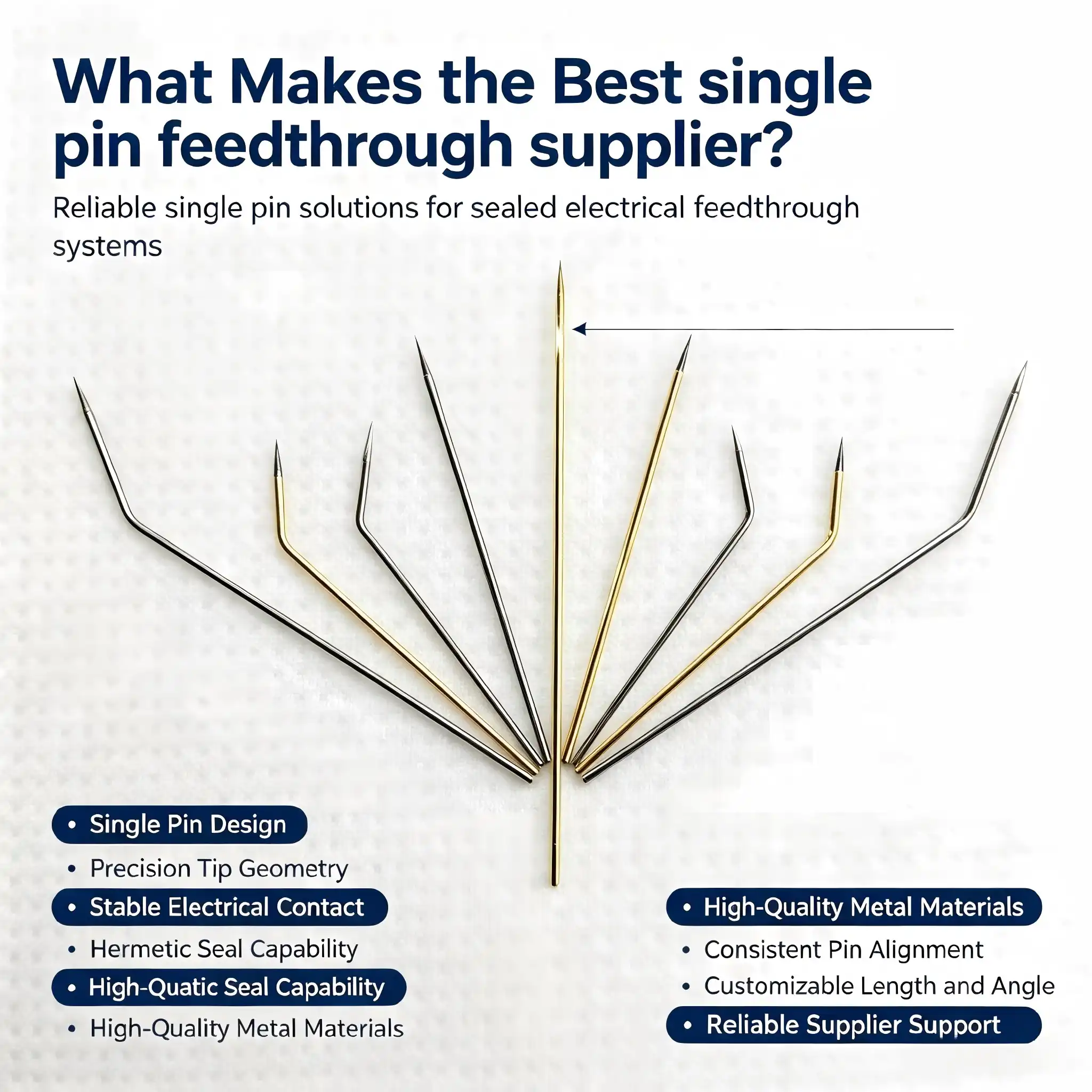
Selecting the best single-pin feedthrough supplier requires careful evaluation of technical capabilities, quality systems, and operational reliability. A superior supplier delivers hermetically sealed components with verified leak rates, maintains comprehensive certification compliance, offers customization expertise, and provides transparent communication throughout the procurement cycle. The right partner understands your specific environmental requirements—whether vacuum, pressure, or temperature extremes—and delivers solutions backed by rigorous testing protocols and responsive technical support that minimize project risk.
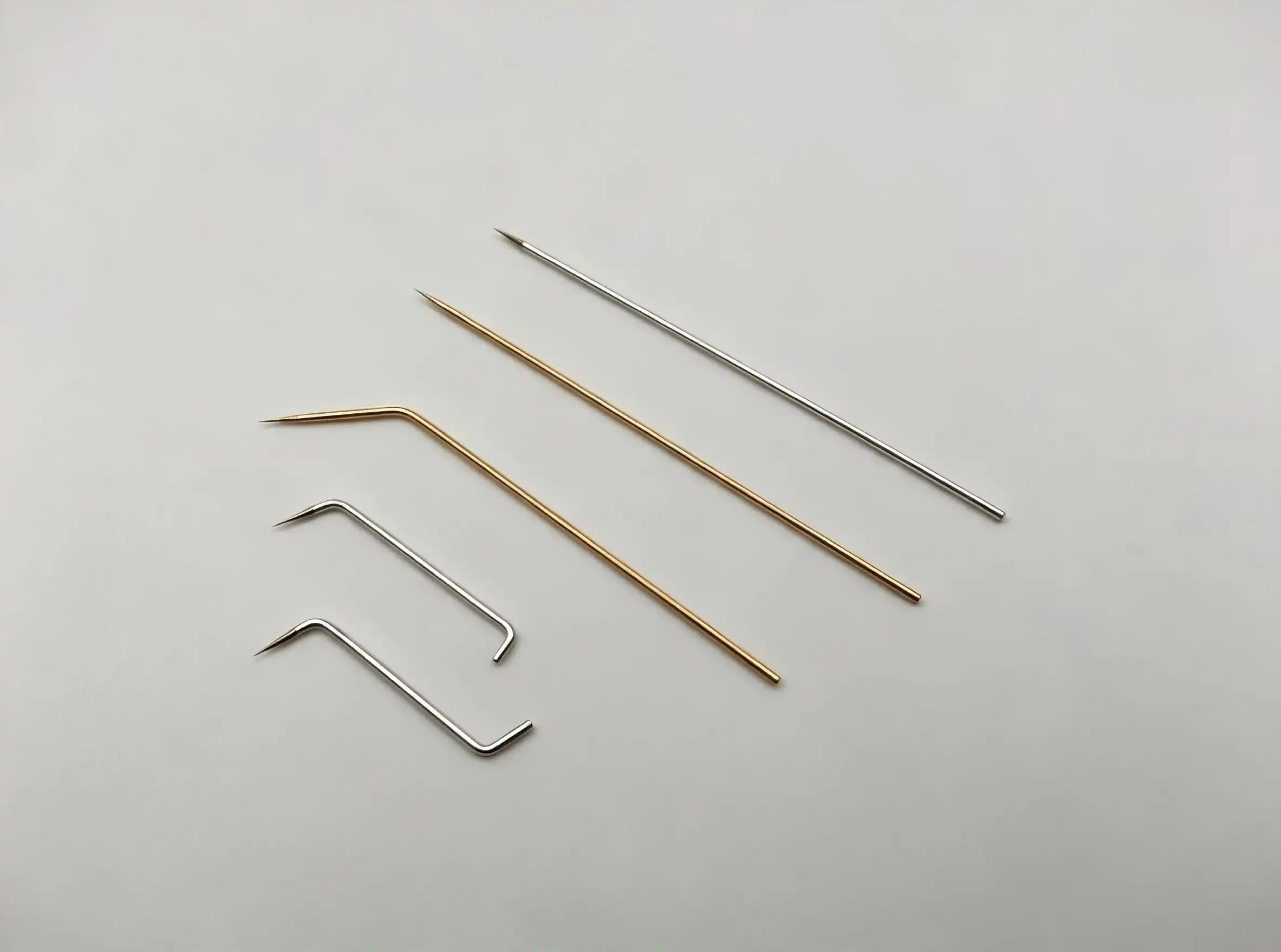
Core Criteria to Evaluate When Choosing a Single Pin Feedthrough Supplier
Setting clear evaluation criteria before hiring potential suppliers makes the whole process of buying things a lot more efficient. We've found that systematic assessment cuts down on project delays and makes sure that the skills of the supplier match the needs of the application.
Quality Assurance and Certification Compliance
A reliable single-pin feedthrough supplier has a number of quality approvals that show they make great products. ISO 9001 certification shows basic quality management, and AS9100 certification shows methods that are fit for aircraft use. RoHS and REACH compliance make sure that materials are safe and that people care about the earth. Suppliers who work with the defense industry should have the right security clearances and be able to show that they follow MIL-STD-1344 or MIL-DTL-38999. Check the supplier's quality paperwork methods as well as their certifications. Standard offerings should include a proof of conformance, test records, and the ability to track down materials. Helium leak tests with recorded results prove hermetic integrity. This is especially important for vacuum uses where even tiny leaks can break the system.
Product Range and Customization Capabilities
Standard store items can be used for common tasks, but they often need to be changed for more specific jobs. The best suppliers keep a large selection of standard products and offer engineering help for custom designs. Check to see if the supplier can change the pin diameter, housing size, insulation materials, and plating choices to meet your needs. Suppliers who offer CAD models and technical drawings in more than one format are valued by design engineers. Custom prototyping with reasonable lead times lets you test things out before committing to large-scale production. Suppliers who have their own engineering teams can work together to solve problems that are unique to a certain application by offering design changes that make the product work better or cost less.
Lead Time Management and Supply Chain Reliability
Production plans depend on being able to predict when parts will arrive. Project bottlenecks can be avoided by knowing a supplier's manufacturing capacity and normal wait times. Well-run sellers give realistic deadlines and information on the status of custom orders. Planning your inventory is affected by minimum order quantities (MOQs). MOQs that are flexible allow for both prototype development and production scaling. Being close to manufacturing hubs or strategically placing supplies can speed up delivery for urgent needs. Being open about where raw materials come from and when production will happen in the supply chain builds trust in delivery promises. Backup manufacturing capacity and backup plans show that you are ready for changes in demand or problems with supply.
Pricing Structure and Total Cost Analysis
The price of the parts at the start is only one part of the total cost of ownership. Check to see if prices are the same across all order sizes, and look into ways to break down orders in a way that lowers the cost per unit. It is important to be clear about any hidden costs, such as tooling charges, engineering fees, or expedite premiums, from the start. Reliability creates long-term value; parts that break down too soon cause replacement costs, lost production time, and possible guarantee claims that are much higher than the initial savings. Clear quotation processes with detailed breakdowns make it possible to plan a budget that works. When you buy something from another country, the payment terms and currency options are important. So are the shipping plans and help with customs paperwork.
Comparing Single Pin Feedthrough Suppliers: What Sets the Best Apart?
Once you've used basic criteria to narrow down the list of possible sellers, a more in-depth comparison will show you important differences that will affect the success of your long-term relationship. We suggest looking at both the tangible and the intangible factors that make a supplier great.
Specialization Versus Broad Product Portfolios
Some providers only sell hermetic feedthroughs and the sealing technology that goes with them. They become very good at glass-to-metal sealing methods, vacuum technology, and ways to test for leaks. This level of specialization usually means better technological help and new ways to solve problems in difficult situations. On the other hand, larger companies that make electrical connectors might offer both single-pin feedthroughs and multi-pin setups, which is helpful for projects that need more than one type of connection. For hermetic applications, specialized suppliers usually keep tighter tolerances and stricter testing protocols. Experience with multiple pin feedthroughs can help with single-pin designs, especially when it comes to managing current density and temperature.
Track Record and Customer Validation
Verified customer reviews give you an idea of how well a seller really does in the real world. In addition to marketing materials, you should also look at reviews from outside sources, case studies with measurable results, and industry references. Suppliers that work with tough industries like aerospace and medical devices have shown they can meet strict needs. Putting out technical papers or patents shows that you are innovative and have a lot of technical knowledge. Membership in industry groups and attendance at conferences are signs of active involvement with new technologies and standards. Consistency and dependability are proven by long-term partnerships with big OEMs. Ask for references from customers who have used similar products and numbers to what you want to do.
Technical Support and Warranty Policies
Accessible tech help is what sets great providers apart from just-good ones. Pre-sale advice helps set the best specs and avoids mistakes in design that cost a lot of money. During integration, quick expert support answers questions about installation and fixes problems that come up out of the blue. Post-delivery support takes care of problems in the field and helps find the root cause of problems when they happen. A full guarantee that lasts for 12 to 24 months shows that the company that made the product is confident in its quality. Having clear warranty terms that spell out the conditions of coverage and how to file a claim stops arguments. Some providers offer longer warranties or performance guarantees for uses that are very important. The quality of the technical documentation, which includes installation instructions and handling instructions, shows how much the supplier cares about the success of their customers.
Sustainability and Compliance Commitments
Environmental and legal factors are being taken into account more and more in modern buying, beyond just how well the product works. Suppliers who are committed to sustainable manufacturing practices reduce their impact on the environment by reducing waste, saving energy, and sourcing materials in a responsible way. Reporting on conflict minerals and being open about the supply chain are both good examples of business social responsibility. Legal problems can be avoided in the future by following new rules like California's Proposition 65 or European Union directives. Environmental standards, such as ISO 14001, show that environmental management is done in a planned way. The circular economy is based on programs that recycle or reuse materials at the end of their useful lives. Suppliers who keep an eye on changes to regulations help customers stay in line as requirements change.
Streamlining Procurement: Best Practices for Ordering Single Pin Feedthroughs
Procurement methods that work well cut down on clerical work and speed up project timelines. We've come up with useful methods that make finding parts easier while still making sure they meet specifications.
Requesting Quotes and Technical Samples
Request for Quote (RFQ) packages that are well-thought-out get accurate replies and cut down on iteration rounds. Include all technical details, such as the diameter and material of the conductor, the type of insulation, the size and material of the housing, the rated voltage and current, the working temperature range, the conditions of exposure to the environment, and any certificates that are needed. Give information about the application, such as vacuum levels, pressure differences, vibration exposure, and expected lifetimes. This will help providers suggest the best designs. Ask for CAD models or dimensional drawings to quickly check if the parts will work together mechanically. Requesting samples lets you check the product physically before committing to production. This is especially helpful when switching to a new single-pin feedthrough supplier or making custom designs.
Managing Lead Times and Volume Orders
Knowing how production cycles work lets you make realistic plans for your schedule. Most standard goods are shipped within days, but unique designs may need weeks to be prototyped and approved. Make sure everyone knows when things need to be done on a project, and make sure you differentiate between prototype needs and production release times. Making a promise to a certain volume can sometimes lead to better prices or more manufacturing slots. To balance the costs of keeping inventory with the need to keep making things, you might want to use blanket purchase orders with scheduled releases. Having a buffer stock of long-lead items guards against sudden increases in demand or problems with supply. Forecasting insight helps providers use their resources and raw materials more effectively, which could make them more flexible.
Logistics and Risk Mitigation Strategies
When you buy something from another country, things like shipping, clearing customs, and legal paperwork can get complicated. Make sure you understand the shipping terms (FOB, CIF, DDP) so you know who is responsible for costs and where the risk lies. Suppliers who know how to export goods give correct commercial invoices, certificates of origin, and technical paperwork that meet customs requirements. Good packaging keeps things from getting damaged during shipping; sealed parts need to be kept safe from water and shocks. Having insurance protects you from loss or damage. Diversified buying from more than one provider or geographic area lowers the risk of a single point of failure. However, the costs of qualification must be weighed against the benefits of lowering risk. Regular checks of suppliers make sure they can keep doing what they're doing and find any problems before they affect service.
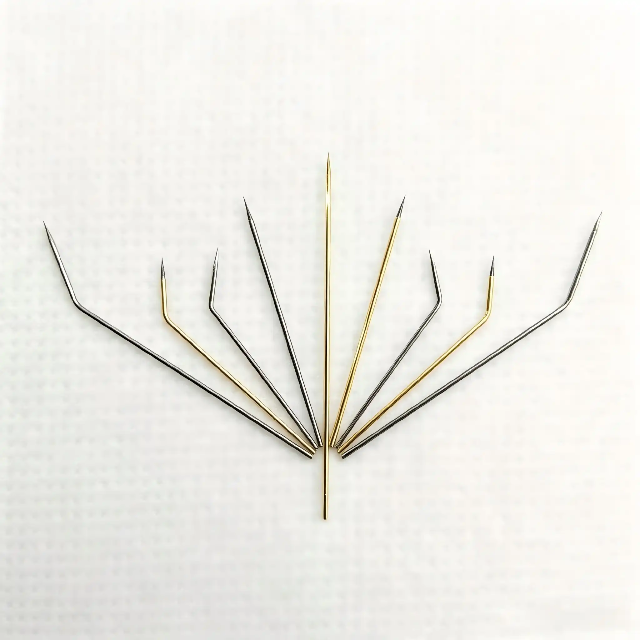
Why Chuangyu Is Your Trusted Single Pin Feedthrough Partner
Shaanxi Chuangyu Electronic Technology Co., Ltd. has become a trusted single-pin feedthrough supplier by offering a wide range of manufacturing services and putting the needs of customers first. We are experts in making precise electrical plugs and RF components, which gives us the technical know-how to make sealed feedthrough solutions that meet the most stringent needs of our customers.
Comprehensive Manufacturing Capabilities
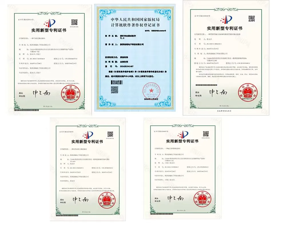
Our factory in the Xi'an Chang'an Innovation Technology Industrial Park has specialized tools for a number of different feedthrough technologies. The Kovar alloy glass encapsulation production line can make sure that the seal is completely hermetic, and the leak rates are known to be acceptable for both vacuum and pressure situations. We can make 500,000 RF components and 1 million test probes every year, which means we have the factory scale to handle both making prototypes and making a lot of them. Precision machining, glass sealing, metallization, and plating are all done in our 800-square-meter production workshop. This makes sure that the quality of the work is consistent and that the process is under control. The 200-square-meter research and development (R&D) lab helps with custom design development and validation testing, such as finding helium leaks, testing at high voltages, and checking how well devices respond to thermal cycling.
Engineering Expertise and Customization Services
Our method for unique feedthrough design is based on almost twenty years of experience in the field. Our engineering team works with customers to find the best specs for vacuum tanks, pressure vessels, and electromagnetic shielding enclosures, among other things. We help with designing the right-sized conductors, insulation materials, and housings so that electrical performance, functional needs, and cost goals are all met. High-speed PCB design lets you help with more than just supplying parts for system integration. Custom, non-standard probe development experience directly applies to specialized feedthrough applications that need special shapes or high-performance standards. Our fast, iterative prototyping method lets you test your idea before committing to production.
Quality Management and Certification Credentials
Every step of the manufacturing process is governed by strict quality control rules, from inspecting new materials as they come in to testing and packing them at the end. Our quality management system includes inspection methods that are in line with global standards for test equipment and RF communication parts. Material traceability makes sure that there is proof that connects finished parts to certifications for raw materials and process parameters. Electrical testing makes sure that each production lot has the right amount of insulation resistance, contact resistance, and voltage withstand capability. Helium leak testing confirms the hermetic integrity and gives recorded leak rates that meet customer requirements. To make sure the performance works in a range of situations, environmental testing can include changing temperatures, heat shock, and exposure to humidity.
Responsive Service and Flexible Order Handling
Because we know that project needs are very different, we've set up our business to meet the wants of all of our customers. Flexible minimum order numbers help early-stage development projects and test prototypes without forcing customers to commit to large amounts of work too soon. Because we are close to the Xi'an High-tech Industrial Park supply chain tools, our order response cycle is about 20% faster than the average for our business. Technical support that can be reached through a variety of methods makes sure that questions about applications and help with fixing problems are answered quickly. We keep clear communication about the status of production and let customers know ahead of time about any changes that might affect the schedule. Our 150-square-meter warehouse and logistics center make it easy to ship items and fulfill orders.
Proven Industry Partnerships
Our customers come from the photovoltaic, medical, communications, automation, and new energy industries, showing that we can handle a wide range of difficult tasks. Our precision test probes and electrical interconnect solutions for quality control systems are used by some of the biggest names in photovoltaics. Our millimeter-wave connectors and cable systems are used in next-generation infrastructure by high-end RF transmission companies. Medical device makers appreciate our dedication to quality and dependability for equipment that needs to keep working well over time. These long-term partnerships show that we can meet strict technical requirements while also providing reliable service that helps customers succeed.
Conclusion
To find the best single pin feedthrough supplier, you need to carefully look at their technical skills, quality control systems, operating dependability, and dedication to customer service. The best supplier offers hermetically sealed parts whose performance has been tested, keeps up-to-date certifications, offers customization expertise, and offers quick support throughout the entire procurement and application lifecycle. The dependability of a component and its total cost of ownership are directly affected by the materials used, the manufacturing method, and the testing standards.
Chuangyu combines its specialized manufacturing skills with its engineering know-how and service delivery that is focused on the customer. We can serve a wide range of uses in the aircraft, medical, industrial, and telecommunications sectors thanks to our integrated production center, quality management systems, and established ties with other companies in the same field. We have the technical depth and operational freedom to help your project succeed, whether you need standard setups or solutions that are made just for you.
FAQ
1. What factors influence single-pin feedthrough pricing?
The price depends on the size of the housing, the type of insulation, the diameter of the conductor, the required certifications, and the plating specifications. When compared to normal catalog goods, custom designs with unique shapes or materials cost more. Order volume has a big effect on per-unit costs, and you can usually get discounts for larger orders. It costs more to do tests like finding helium leaks or making sure the high voltage works. Manufacturing costs go up when there are complicated finishing requirements or unusual materials used. When you look at the total cost, you should think about how reliable and long-lasting the parts are, because high-quality parts often have better lifecycle value.
2. How is hermetic seal integrity verified and maintained?
Helium mass spectrometer leak testing is used for hermetic integrity verification because it is the most sensitive way to find tiny leaks. Helium tracer gas is used to put pressure on the parts, and any leakage through the sealing interfaces is measured. Leak rates that are acceptable depend on the application. For vacuum uses, they are usually between 1×10⁻⁷ and 1×10⁻⁹ atm·cc/sec. The integrity of the seal depends on how well the glass and metal are bonded and how well the thermal expansions are matched. Seals don't break down before they are installed if they are stored in dry places and are handled carefully.
3. Can Chuangyu accommodate expedited delivery schedules?
We keep our production schedules flexible so that we can meet urgent needs when it is technically possible to do so. Standard items that are already in stock can usually be shipped within days. Custom plans need to be approved by engineers and set up for production, but we try to speed up projects whenever we can. Early discussion about time limits helps with planning ahead and allocating resources. Our closeness to resources in the supply chain and our ability to make things all in one place allow us to turn around orders faster than suppliers who rely on outside subcontractors.
Partner with Chuangyu for Reliable Single Pin Feedthrough Solutions
When looking for a single pin feedthrough supplier for your important uses, you need to think carefully about their technical skills, quality systems, and quick service. Chuangyu offers hermetic feedthrough solutions that are exactly what you need by combining specialized manufacturing knowledge with full engineering support. Our Xi'an factory uses precise machining, glass sealing technology, and strict testing procedures to make sure that parts will work reliably in harsh conditions. Email our team at chuangyuwz01@cymicrowave.com to talk about your unique needs and get personalized technical advice.
References
1. Henderson, G. L. (2018). Hermetic Sealing Technology for Electronic Components: Materials, Processes, and Reliability. IEEE Press Series on Microelectronic Systems.
2. Pecht, M., & Kang, M. (2019). Electrical Connectors for Harsh Environments: Design, Testing, and Failure Analysis. John Wiley & Sons.
3. Klein Wassink, R. J. (2020). Glass-to-Metal Seals: Fundamentals, Applications, and Quality Assurance. Elsevier Advanced Technology.
4. Zhang, W., & Thompson, R. (2021). "Vacuum Feedthrough Design Considerations for Semiconductor Manufacturing Equipment." Journal of Vacuum Science & Technology, 39(4), 042801.
5. Military Standard MIL-DTL-38999. (2017). Connectors, Electrical, Circular, Miniature, High Density, Quick Disconnect, Environment Resistant, Removable Crimp and Hermetic Solder Contacts.
6. Peterson, K. A., & Speranzini, S. (2022). "Reliability Assessment of Hermetic Feedthroughs in Medical Implantable Devices." IEEE Transactions on Device and Materials Reliability, 22(1), 45-53.
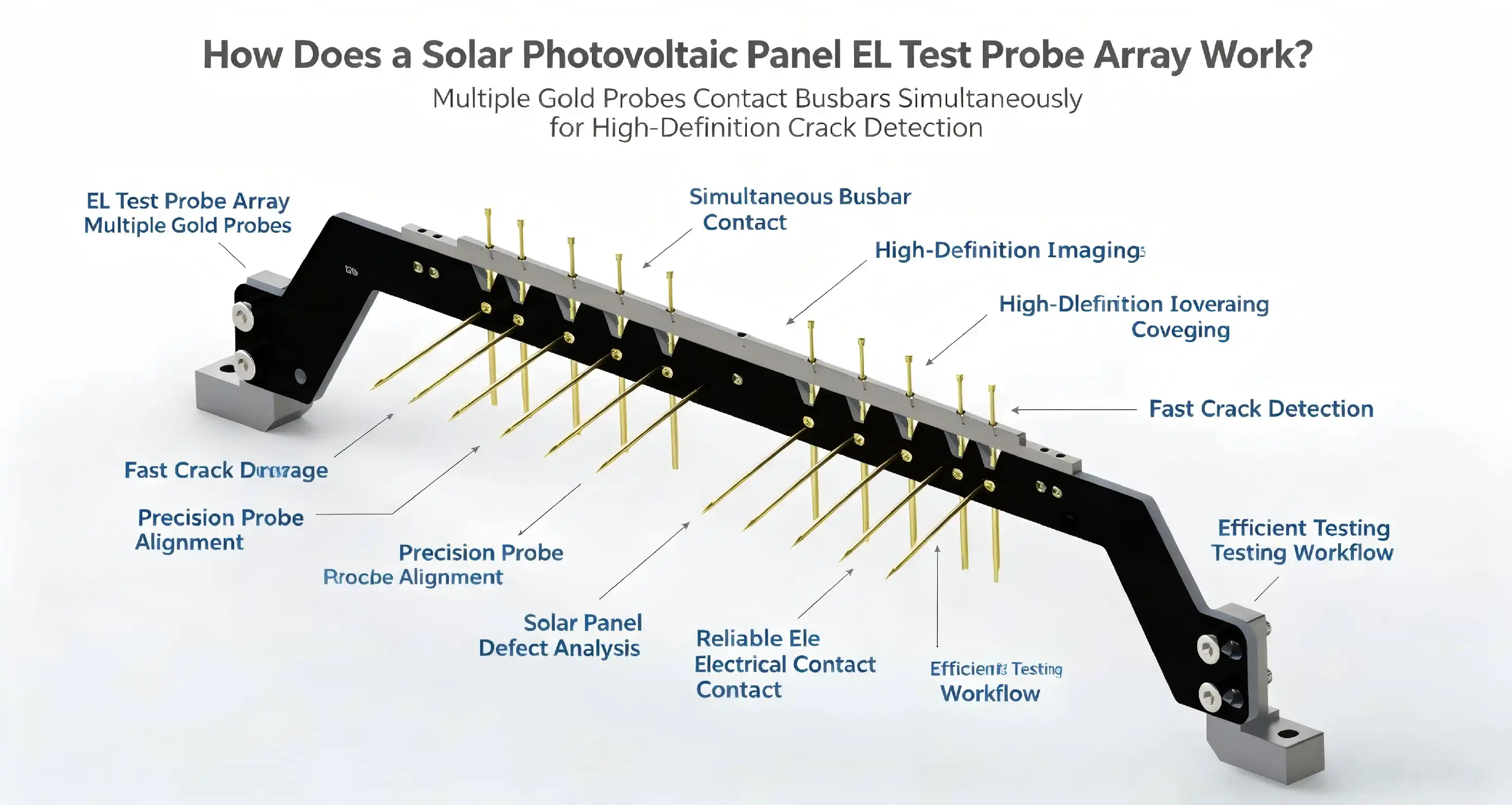
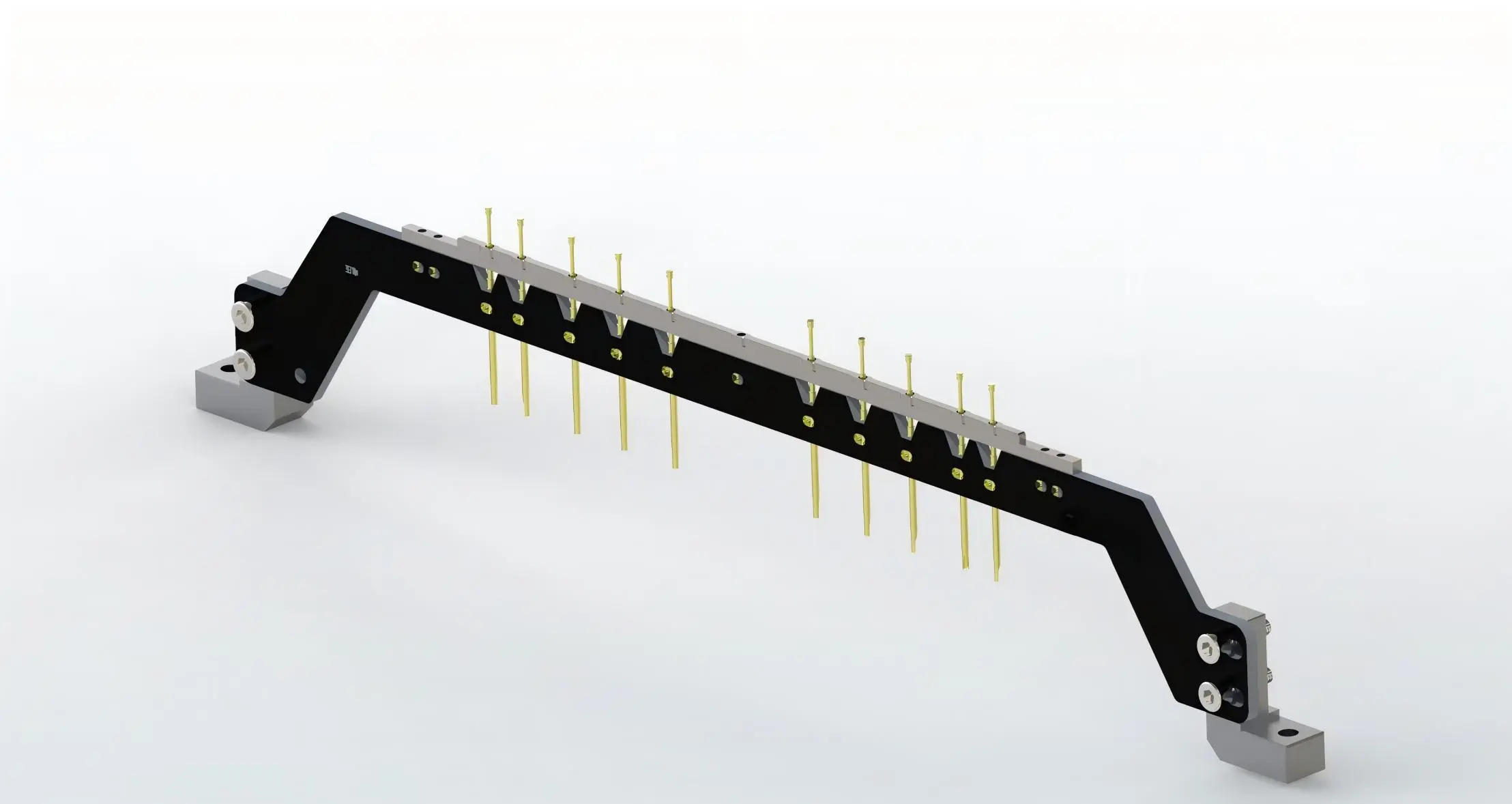
A solar photovoltaic panel EL test probe array operates by injecting controlled electrical current into photovoltaic cells through precision probes, triggering electroluminescence emissions that reveal hidden internal defects invisible to conventional inspection methods. These arrays feature multiple gold-plated probes arranged to contact the main grid and fine grid lines simultaneously, enabling comprehensive quality assessment through luminescent imaging that identifies micro-cracks, broken grids, and soldering imperfections across the entire cell surface with exceptional clarity and speed.
Understanding the Fundamentals of Photovoltaic EL Testing Technology
Solar companies are always looking for reliable ways to keep quality control high so they can keep up production standards. Electroluminescence testing has become a revolutionary method that gives users a unique look into the health of cells before the modules are sent to them.
The Science Behind Electroluminescence Detection
When electricity flows through silicon solar cells, electrons get excited and send out infrared light that can be picked up by certain cameras. We can see electrical activity going on all over the cell structure because of this effect. In captured images, defects show up as dark spots or wavy lines, which gives a diagnostic path that standard eye inspection can't match. The technology finds damage on a microscopic level, finding issues that would otherwise lead to failures in the field months or years after they were installed.
Essential Components of EL Test Systems
A full electroluminescence testing system has a number of important parts that work together. The probe array sends current exactly where it's needed, and in testing rooms that are dark, sensitive infrared cameras record emission patterns. Environmental controls keep things the same, so the findings of the thousands of tests that happen every day can be repeated. Modern systems have automatic positioning systems that line up probes within 0.2 mm of each other. This protects weak cells and makes touch more reliable. Control software plans the whole process, from applying power to analyzing images and classifying defects.
Why Probe Arrays Matter in Production Environments
For mass production to work, it needs to be fast without sacrificing accuracy. Multi-probe configurations solve this problem by scanning whole cells at once instead of one point at a time. This parallel method cuts cycle times by a huge amount and works perfectly with high-volume production lines that process thousands of cells every hour. The arrays can be changed to fit different cell sizes, such as 166mm, 182mm, or 210mm, thanks to modular bracket systems that let you precisely set the probe spacing. This versatility is very helpful for companies that want to switch between different product lines without having to wait a long time for retooling.
Benefits of Using EL Test Probe Arrays in Photovoltaic Inspection
Electroluminescence testing is becoming more and more popular among quality assurance teams because it has real benefits over older checking methods. The technology gets around the problems that come with visual inspection and thermal imaging.
Superior Defect Detection Accuracy
EL testing finds tiny cracks smaller than 50 microns, broken grid fingers that only affect a few cells, and bad solder joints that make it hard for electricity to flow. These small flaws make conversion less efficient and create hotspots that speed up degradation. Manufacturers protect their reputation and avoid expensive warranty claims by finding flaws before they are shipped. The Solar photovoltaic panel EL test probe array makes sure that the current is evenly spread across all test points. This stops the false negatives that can happen when lighting or temperature changes unevenly in other methods.
Enhanced Production Efficiency and Throughput
Quality control can be a bottleneck, but with inline integration, it can be a competitive advantage. Automated systems constantly process cells and decide within seconds whether they pass or fail. This quick feedback lets process changes happen right away when failure rates go up, stopping big batches of bad product. The parallel testing design makes the best use of the tools because each array can check multiple cells per minute while still being very strict. Production planners like that cycle times are predictable because it makes planning schedules and capacity easier.
Long-Term Cost Reduction and ROI
The initial cost of buying equipment pays off in the long run by lowering field failures and raising yields. As fewer defective modules reach customers, warranty costs go down, and as manufacturing efficiency goes up, margins go up directly. When EL image data is analyzed, trends are found that help engineers improve manufacturing parameters in a planned way. Facilities report an ROI of more than 300% over a typical five-year operating period, which includes direct savings, increased productivity, and benefits to their quality reputation.
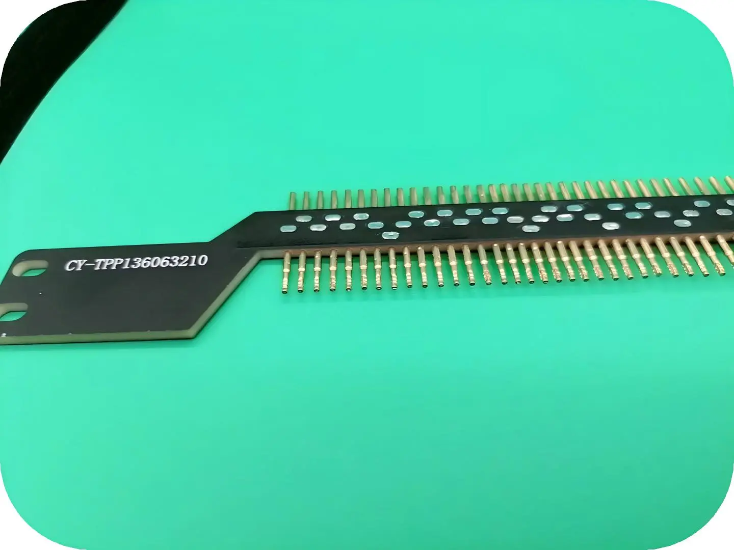
Key Features to Consider When Selecting a Solar EL Test Probe Array
When making a procurement choice, technical specifications must be carefully matched to practical needs. Not every probe array works the same way in all kinds of manufacturing situations.
Precision and Mechanical Adaptability
The Solar photovoltaic panel EL test probe array design needs to be able to accommodate different cell architectures without affecting the alignment accuracy. Modular bracket systems let you change the spacing to fit common formats, and mechanical positioning structures or visual alignment aids keep the important 0.2mm tolerance level. Controlling the probe contact pressure keeps cells from getting damaged, which is especially important for thin-film technologies like HJT, and makes sure that the electrical link is stable. Systems that can handle contact pressures below 200 grams-force per probe are the most gentle and conduct electricity best.
Electrical Performance and Signal Integrity
For signal quality to stay high, low-impedance links between probes and conductive paths are necessary. Gold-plated probe surfaces are very good at conducting electricity and don't rust or wear down easily in settings with a lot of testing. Manufacturers say how long something will last by rating how many times it can be inserted and removed. The best arrays keep working well after more than 10,000 daily operations. This makes things last longer, which lowers the cost of replacement and maintenance, which is an advantage for the total cost of ownership. Signal attenuation has a direct effect on the clarity of an EL picture, so when evaluating vendors, it is important to pay close attention to the probe material choice and connection design.
Durability in Industrial Conditions
Conditions on production lines are very tough, and they work nonstop. Changes in temperature, exposure to dust, and mechanical vibration test equipment's durability. These stresses can be reliably handled by probe arrays made of materials that don't corrode and protective coatings. Gold plating does two things: it improves the electrical qualities of something and protects it from external damage. Strong construction cuts down on downtime, so production goals can still be met even during long campaigns. Check the suppliers' certifications and ask for performance data from similar industrial uses when you're evaluating them.
The EL Test Probe Array Testing Process Step-by-Step
Understanding the operational sequence helps engineers get the most out of their equipment and figure out what's wrong quickly. Each step improves the quality of the data as a whole.
Pre-Test Inspection and Setup Procedures
Before testing starts, workers make sure the probe is still intact by looking for deformation, coating separation, or link looseness. Broken probes need to be replaced right away to avoid getting wrong results or damaging cells. The probe array is carefully aligned to the cell grid lines during installation. Vision tools are often used to help check that the array is in the right place. As part of environmental preparation, the test room is made darker and the temperature is kept within certain ranges. This gets rid of any changes that could affect the patterns of electroluminescence emission.
Current Application and Image Capture
As soon as everything is lined up, the system sends a steady voltage through the probe array to the cell. Current flows through the grid lines, which causes electroluminescence that is related to the electrical activity in the area. During this short time of activation, which usually lasts only seconds, high-sensitivity infrared cameras take pictures of the emission. The Solar photovoltaic panel EL test probe array makes sure that the current flows evenly across many contact points. This creates pictures that are evenly lit and clearly show flaws against the background of normal emission. The right choice of voltage combines the brightness of the picture with the risk of damaging cells that are already damaged.
Image Analysis and Defect Identification
Images are automatically analyzed by matching emission patterns to standards that have already been set. Dark spots show tiny cracks or areas that aren't working, while uneven changes in light show broken grid fingers or bad connections. Modern software uses machine learning algorithms that were taught on thousands of cases of bugs and can correctly classify more than 95% of them. Reviewers who aren't computers check cases that aren't clear, which builds expertise that makes automated system training better over time. This approach is a mix of speed and judgment, so it can find small problems that pure automation might miss.
Troubleshooting Common Testing Challenges
Systematic diagnosis finds the reasons why EL images show dark stripes or spots that don't make sense. Probes that aren't lined up right make patterns that can be told apart from real cell flaws. Probe tips that are worn down make contact less good, which makes the light less bright or uneven. When there is too much contact pressure, compression marks can be seen on later images. Operators use debugging guides that cover these situations to fix problems and then start testing again. Regular calibration checks make sure that the system is working correctly and that measurements can be trusted by all machine workers and production shifts.
Procurement Guide: Selecting the Right EL Test Probe Array Solution
When technical buyers need to find electroluminescence testing tools, they have a lot of choices. Strategic evaluation frameworks make it easier to make choices and keep capabilities and needs from not matching up, which can be expensive.
Assessing Your Specific Testing Requirements
The amount of production determines how much space is needed for equipment. Research labs that test 50 samples a week need different solutions than facilities that process 5,000 cells every day. Cell technology affects probe design; the grid patterns and width profiles of the PERC, TOPCon, and HJT designs are all different. Different tasks need different levels of accuracy when measuring. For example, research and development needs higher resolution than regular production screening. Writing down these factors gives vendors a place to start when they talk about possible systems. This way, you can be sure that the systems being considered will solve real practical problems, not just general requirements.
Comparing Manufacturers and Supplier Credentials
Suppliers that have been around for a while have a track record of reliability and a full support system. Companies that have been in the photovoltaic industry for a long time know more about how to make things than new companies that sell generic test equipment. Credentials like certifications confirm good quality management, and customer references show how quick service is after the sale. Warranty terms protect investments, but equipment that works well doesn't need much maintenance. Training programs help operators become more skilled faster by lowering the learning curve that slows down production integration. The Solar photovoltaic panel EL test probe array from reputable manufacturers comes with instructions, spare parts, and access to technical support—all of which are important for long-term operational success.
Balancing Cost, Quality, and Long-Term Value
The purchase price is only one part of the total costs of owning a home. Over the life of an item, the costs of energy use, regular upkeep, and new parts add up. When spread out over years of reliable service with little downtime, a higher initial investment often ends up being a good deal. When figuring out career costs, procurement teams should include the extra work that comes from faster cycle times and better defect spotting. Having a variety of financing options makes it easier to deal with limited funds without lowering the quality of the equipment. Strategic sourcing strikes a balance between short-term budget needs and long-term goals of operational efficiency and quality assurance.
Conclusion
The Solar photovoltaic panel EL test probe array is an important quality control tool for companies that want to make sure their solar goods are stable. These systems find tiny cracks, broken grids, and soldering flaws that hurt performance and durability by precisely injecting current and using electroluminescence imaging. Strategically choosing equipment that balances accuracy, durability, and operating efficiency helps meet output goals while keeping costs low. As photovoltaic technology moves toward designs with better efficiency, EL testing must also change to keep up. For long-term success, it is important to have relationships with suppliers.
FAQ
What advantages does EL testing offer compared to traditional visual inspection methods?
Electroluminescence testing shows electrical problems inside that can't be seen from the outside. Micro-cracks spreading below the surfaces of cells, broken grid fingers that make it hard to collect current, and bad solder joints that make it hard to connect all show up clearly in EL images but can't be seen. This deep-level knowledge stops failures in the field that hurt companies' reputations and cost them money in warranty costs.
Can probe arrays accommodate different solar cell technologies and sizes?
Modern Solar photovoltaic panel EL test probe arrays have modular designs that can support different cell formats by adjusting the probe spacing. Bracket systems can be quickly changed to fit 166mm, 182mm, and 210mm standards that are popular in production right now. The technology works with PERC, TOPCon, HJT, and new architectures as long as the right voltage parameters and contact pressure adjustments are made to fit the characteristics of each cell.
How often do probe arrays require maintenance and what does it involve?
As part of regular maintenance, photovoltaic-grade solvents and lint-free cloths are used to clean gently and get rid of silver paste residues and oxidation. Before each shift, operators check the probes for deformation or damage to the coating, and they quickly replace any worn parts. Keeping probes in controlled settings free of corrosive gases greatly increases their useful life. Arrays that are well taken care of can withstand thousands of daily test runs in between major service intervals.
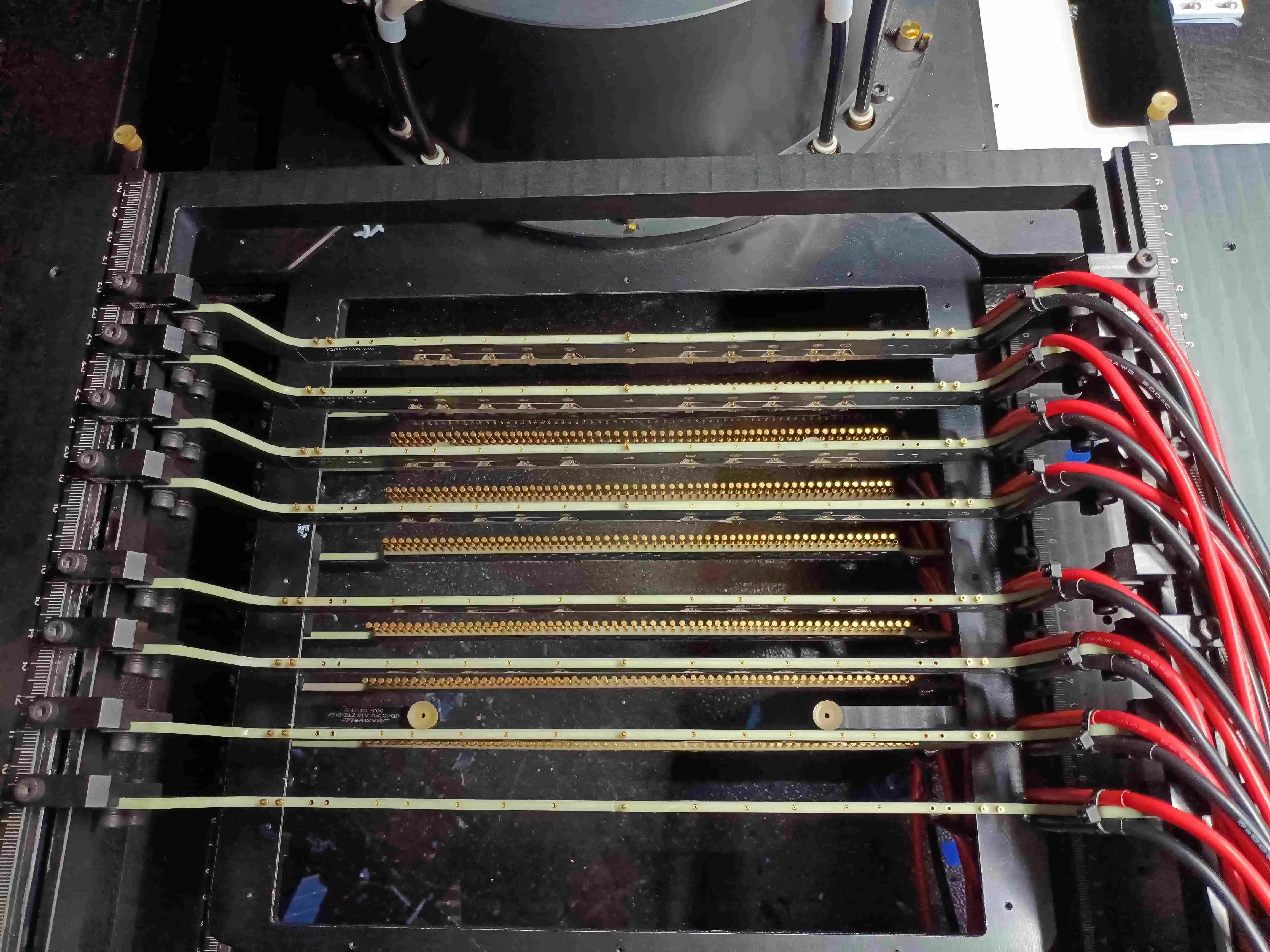
Partner with Chuangyu for Advanced Photovoltaic Testing Solutions
Quality assurance demands precision tools backed by responsive technical support. Chuangyu offers photovoltaic EL test probe arrays that are designed to work in harsh production environments, combining gold-plated multi-probe designs with modular adaptability supporting diverse cell formats. Our low-impedance electrical architecture ensures signal integrity and image clarity, while robust construction maintains stable performance through tens of thousands of testing cycles. As a trusted Solar photovoltaic panel EL test probe array manufacturer, we serve leading photovoltaic enterprises across crystalline silicon production facilities globally. Reach out to our team at chuangyuwz01@cymicrowave.com to discuss customized testing solutions matching your specific production requirements, or visit cymicrowave.com to explore our comprehensive portfolio of precision test probes and RF components.
References
1. Smith, J. (2021). Electroluminescence Imaging in Photovoltaic Manufacturing: Principles and Applications. Solar Energy Press.
2. Zhang, L., & Kumar, R. (2022). "Advanced Defect Detection Methods for Crystalline Silicon Solar Cells." Journal of Photovoltaic Technology, 15(3), 234-251.
3. Anderson, M. (2020). Quality Assurance in Solar Module Production: A Comprehensive Guide. Renewable Energy Publications.
4. Chen, W., et al. (2023). "Multi-Probe Array Design for High-Throughput EL Testing of PERC and TOPCon Cells." International Solar Manufacturing Review, 8(2), 112-128.
5. European Photovoltaic Industry Association (2022). Best Practices for Solar Cell Inspection and Testing Standards. EPIA Technical Report Series.
6. Rodriguez, F., & Tanaka, H. (2021). "Cost-Benefit Analysis of Inline EL Testing in Mass Production Environments." Photovoltaic Economics Quarterly, 12(4), 89-104.
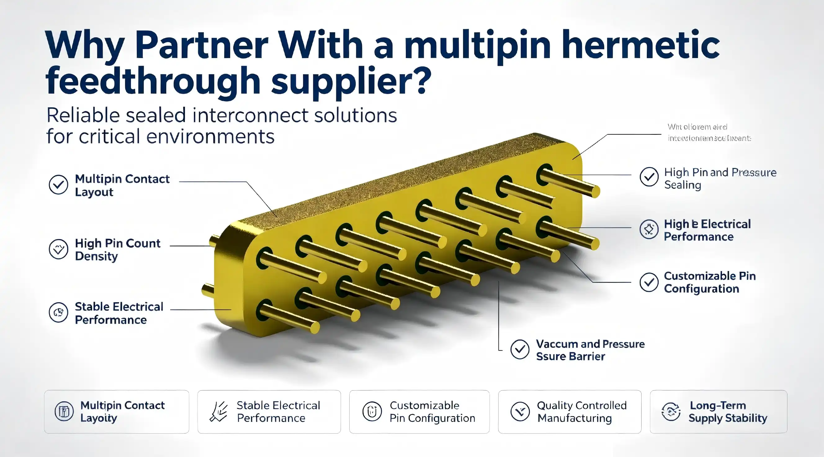
Partnering with a specialized multipin hermetic feedthrough supplier directly impacts your project's reliability and long-term success. Unlike generic component distributors, dedicated feedthrough manufacturers understand the critical sealing requirements, environmental challenges, and performance standards your applications demand. A qualified supplier brings engineering expertise, customization capabilities, and quality assurance that extends beyond transactional product delivery. They become strategic partners who support design validation, provide technical consultation during specification development, and ensure seamless integration of hermetic sealing solutions into your production workflow while maintaining consistent quality across every order.
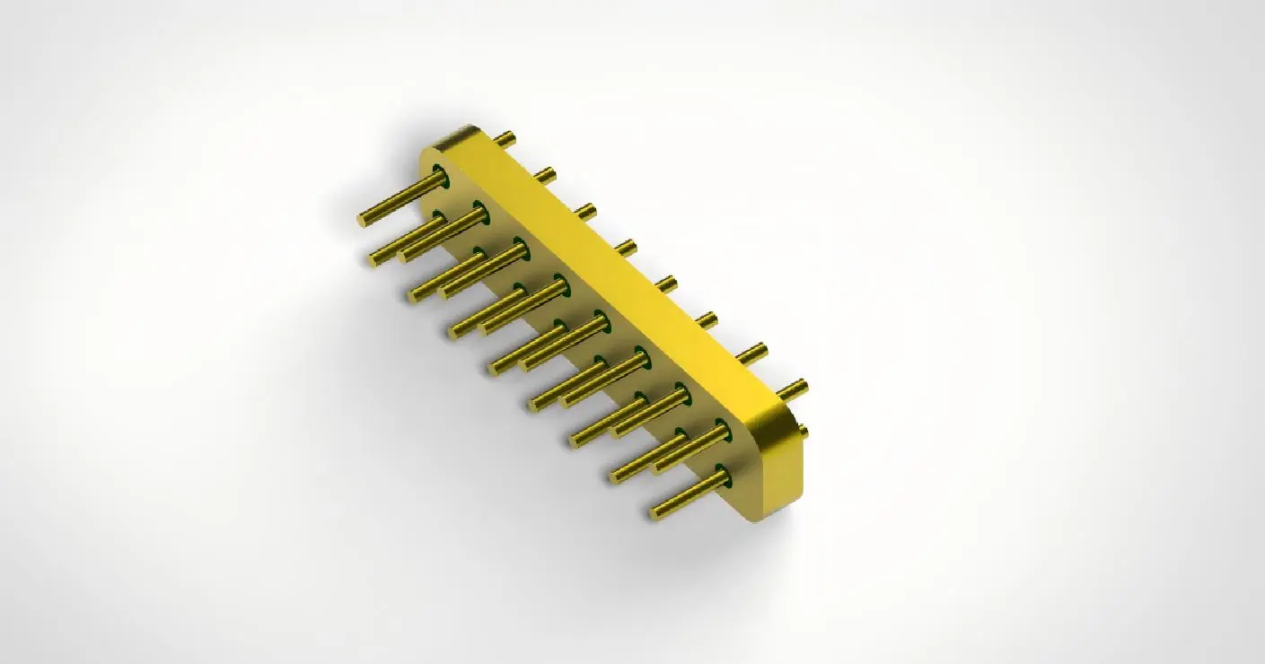
Why Choosing the Right Supplier Matters in Your Procurement Process
Choosing an expert hermetic connector manufacturer has a big impact on the results of the job, going beyond just buying parts. Stability in the supply chain depends on suppliers keeping lead times and inventory levels stable so that production lines don't have to stop. When creating new products, getting engineering help from knowledgeable suppliers speeds up design validation by finding the best pin configurations, voltage ratings, and sealing technologies for the job before spending money on tools.
Quality Assurance and Certification Requirements
Multipin hermetic feedthrough suppliers are different from general electronics distributors because they have strict quality control processes. Every production unit goes through helium leak testing to make sure the integrity of the hermetic seal. Test results show the leak rates and confirm that the standards were met. Manufacturing certifications like ISO 9001, AS9100 for aircraft use, and ISO 13485 for medical products show that quality control systems are in place and that processes can be repeated and tracked throughout production.
When looking for glass-to-metal sealed feedthroughs for medical uses, material approvals are very important because the make-up of the material directly impacts biocompatibility and long-term implant safety. When suppliers give procurement teams material test reports, RoHS compliance documentation, and REACH declarations, they can meet regulatory requirements without having to do extra testing that slows down projects.
Testing for electromagnetic compatibility and measuring shielding effectiveness above 85dB show that multipin hermetic assemblies keep signals pure in RF environments and stop interference that could damage measuring tools or communication systems that depend on clean electrical connections through sealed barriers.
Customization Capabilities and OEM Collaboration
Standard catalog goods don't always meet the exact needs of a specific application. Because of this, the ability to customize products is an important factor to consider when comparing different providers. Manufacturers with a lot of experience who offer engineering partnership services work directly with design teams to change the number of pins, the gauges of the conductors, the mounting flanges, and to add special materials that deal with specific weather problems.
OEM partnerships are more than just customizing products. They can also include co-development agreements where suppliers help with design during the concept phase, do feasibility studies that look at different sealing methods, and make prototypes so that they can be tested for functionality before committing to production tooling. When compared to working with transactional providers who don't have the engineering tools to support custom development projects, these collaborative relationships lower development risk and speed up time-to-market.
Flexible minimum order numbers can handle a wide range of production rates, from study prototypes that only need a few units to mass production plans that need thousands of units every month. Structures for volume pricing, stocking programs for frequently bought configurations, and scheduled shipping plans all help to keep buying costs stable and make sure that material supply is in sync with production schedules.
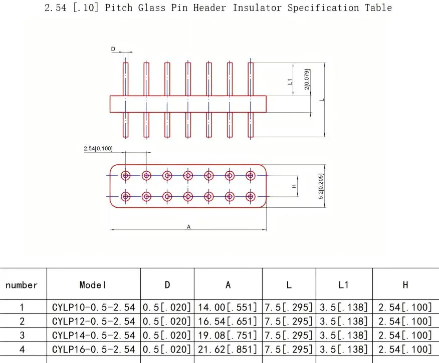
Comparing Multipin Hermetic Feedthrough Suppliers: What to Look For
An effective seller review takes a systematic look at many areas of performance that, when put together, show how likely it is that the relationship will work out. The variety of products available shows how well they can be made and how knowledgeable the staff is in terms of technology. Full catalogs show a wide range of pin configurations, from simple 9-pin arrangements that work for many uses to high-density 100-pin assemblies that support complicated instruments that need many signal paths through single penetrations.
Technical Specifications Alignment
Voltage rating options that range from low-voltage signal transfer to high-voltage power supply up to several kilovolts show that the design is flexible enough to meet a wide range of application needs. Specifications for current capacity range from 3A per pin in standard configurations to 13A in power contact variants. This makes sure that the right size of conductor is used to avoid resistive heating and voltage drop that could hurt circuit performance or cause reliability issues when used for a long time.
Specifications for temperature tolerance should be carefully read, especially for uses that will involve thermal cycling or running all the time at extreme temperatures. Baseline specifications usually cover temperatures between -55°F and +125°F, but some uses need wider ranges. For example, medical autoclave sterilization, downhole oil drilling instruments, and cryogenic research equipment need special types of glass and building materials that can keep airtight seals even when the temperature is above normal.
Pin pitch sizes and general housing shapes affect how well they can be integrated into equipment designs that are limited by space. High-density micro-rectangular configurations achieve 1.27mm pitch spacing, which allows for high conductor counts in small spaces. On the other hand, applications that value easy assembly and field serviceability benefit from larger pitch dimensions, which make wire termination easier and lower the cost of assembly labor.
Supplier Reputation and Market Presence
Industry experience and a supplier's history in the market are good ways to tell if they are stable and have a lot of knowledge. Manufacturers who have been in the aerospace, defense, and medical markets for decades have shown consistent quality performance and gained process knowledge that newcomers can't match, even if they buy the latest equipment. Customer references from well-known companies in the target industries show that the supplier can consistently meet strict requirements.
Suppliers' technical papers, application notes, and engineering tools show how much they know and how willing they are to teach customers instead of just taking orders. White papers that compare sealing technologies, talk about heat management strategies, and design optimization methods help buying teams and engineering staff make smart choices. They also show how well suppliers know how to solve problems that are specific to an application.
Global distribution networks and regional support centers show that a supplier cares about making their products easy for customers to get and helping them after the sale. Having stocking locations in all of the major geographic markets cuts down on shipping times and lets companies respond quickly to urgent needs. At the same time, local technical representatives can help with consultations and custom development projects without the communication delays that come with only working with overseas headquarters.
Seamless Procurement: From Inquiry to Bulk Purchase
Streamlining procurement workflows cuts down on the amount of work that needs to be done by administrators and speeds up project timelines from the initial specification stage to mass production. Easy-to-use online catalogs with parametric search make it easy to find standard products that meet basic needs, and clear quote request processes make it easy to get prices for custom configurations that need engineering input before they can be quoted.
Sample Evaluation and Testing Protocols
Sample request policies that let you evaluate small amounts before committing to larger amounts lower purchase risk by letting you test functionality in real-world application settings. Testing sample units in typical operating conditions makes sure that the performance specs on the datasheet are met and that they work with the connectors, mounting options, and termination methods that are planned for mass production.
Helium leak testing on sample units confirms the integrity of the airtight seal using the same method that is used for production acceptance testing. Before committing to large orders, procurement teams should ask for leak test results that show measured leak rates and confirm compliance with application standards. This way, they can set basic expectations for how well production units will work.
Electrical testing, such as measuring insulation resistance, checking dielectric withstand voltage, and measuring contact resistance, ensures that sample units from a multipin hermetic feedthrough supplier meet electrical requirements that are important for the application to work. Thermal cycling tests that mimic changes in operational temperatures show any possible seal degradation or contact instability that might not show up at room temperature but would lead to failures in the field during real use.
Volume Procurement Optimization
When you buy in bulk, the price per unit is usually much lower than when you buy in small amounts. The volume savings get really big above certain threshold amounts that depend on the source and the complexity of the product. When you negotiate volume price structures during the initial talks about buying something, you set up reliable cost models that help you do accurate costing and profit analysis throughout production programs.
Lead time talks try to find a balance between the costs of keeping stockpiles and the needs of the production plan and the capacity of the suppliers. Standard catalog items usually ship within a few weeks, but for custom configurations that need special tools, lead times can go up to several months for the first production runs. Setting realistic delivery dates keeps customers from having high expectations that put stress on their relationships with suppliers and takes into account the complexity of manufacturing that comes with precision hermetic sealing processes.
Scheduled shipping and stocking programs work best for programs with steady consumption rates. This way, suppliers can keep enough inventory on hand to quickly fill regular orders, and customers don't have to buy or store too much inventory. Scheduled releases from stocking inventory make sure that material arrivals and production plans are in sync. This saves warehouse space and lowers the risk of inventory going out of date in settings where products are constantly being developed.
Future-Proofing Your Technology Stack Through Strategic Supplier Partnerships
Relationships with suppliers that last a long time have strategic benefits that go beyond just buying parts. Working together with creative hermetic feedthrough makers lets you get early access to new sealing technologies, improved materials, and design improvements that make products work better and last longer in harsh conditions.
Technology Advancement and Product Evolution
Leading suppliers spend a lot of money on research and development to improve performance by adding higher voltage ratings, wider temperature ranges, and longer-lasting materials that can handle mechanical stress and exposure to the environment. New developments in glass formulations lower differences in thermal expansion and boost dielectric strength. This lets higher voltage pass through smaller forms, which is good for equipment designs that need to save space.
For ultrahigh-temperature uses, ceramic-to-metal sealing technologies are better than glass sealing because special ceramic materials can keep their airtight integrity above 300℃ for long periods of time. Suppliers who invest in ceramic sealing skills can make products that can be used in harsh environments, which used to require different ways of connecting parts that had their own problems.
Improvements to the manufacturing process, such as automatic checking systems, the use of statistical process control, and more advanced methods for finding leaks, make products more reliable and lower the number of defects they have. Sharing quality metrics and process capability data shows that suppliers are committed to openness and constant improvement, which helps customers by increasing yields and lowering failure rates in the field.
Total Cost of Ownership Advantages
When you look at supplier relationships through the lens of total cost of ownership instead of unit price, you can find hidden value in partnerships that you can rely on. Higher-quality hermetic feedthroughs from well-known suppliers may cost more than cheaper alternatives, but they are more reliable, which means fewer failures in the field, which means lower warranty costs, unhappy customers, and damage to the brand's reputation that is much greater than the difference in component price.
The availability of technical help cuts down on the amount of engineering work that needs to be done to fix application problems and improve designs. Skilled source engineers can offer advice that speeds up development and avoids costly design changes. Working with providers who only give you basic technical information makes design reviews and regulatory applications harder. Documentation that includes thorough drawings, material specs, and performance test data makes things easier.
Supply chain security from financially sound suppliers with a wide range of customers and multiple manufacturing locations lowers the risk of supply disruptions that can stop production and leave inventory investments in units that are still being put together, waiting for parts. When choosing a supplier for a program that will last for more than one year and where the supplier's continuity is important to business operations, the supplier's financial health should be evaluated, and backup plans should be discussed.
Conclusion
Picking the right hermetic connection partner, such as a multipin hermetic feedthrough supplier, affects how reliable a product is, how quickly it can be developed, and how stable the supply chain stays over time for all kinds of demanding uses. Generic distributors can't compete with qualified suppliers when it comes to specialized knowledge, quality control, and the ability to make changes. The price per unit should not be the only thing that is considered when judging a company. Technical knowledge, certification compliance, customization flexibility, and collaborative engineering support should also be taken into account. Strategic partnerships with experienced manufacturers give you access to new sealing technologies and constant product improvements that give you a competitive edge throughout the lifecycle of a product. Reliable supply chains and quick technical support lower operational risks and the total cost of ownership for production programs that last more than one year.
FAQ
1. What distinguishes multipin hermetic feedthroughs from standard electrical connectors?
Through glass-to-metal or ceramic-to-metal bonding, hermetic feedthroughs make completely airtight seals that stop gas and liquid transfer. Leak rates stay below 1.01325×10⁻³Pa·cm³/s, which can be proven by helium mass spectrometry. Standard connectors don't have hermetic sealing, which lets environmental contamination in and causes them to fail early in vacuum, pressure, or moisture-sensitive applications that need complete environmental isolation for long-term reliability.
2. How do I verify hermetic seal quality before bulk orders?
Ask for leak test results that show helium mass spectrometer readings on sample units and confirm that the leak rates found meet the standards of the specification. Do thermal cycling tests that mimic changes in operational temperature, and then check the integrity of the seal again to make sure that it hasn't been damaged. Before starting mass production, look at the glass-to-metal surfaces under a microscope for cracks or holes that could mean the seal isn't working right.
3. What customization options are typically available?
Customization includes changing the number of pins, the gauge of the wire, the design of the mounting flange, the material of the case, the plating choices, and the glass formulas. Experienced providers can make changes to voltage ratings, temperature ranges, and custom pin arrangements that work best for each signal distribution need. They can also provide sample amounts for testing functionality before investing in production tools.
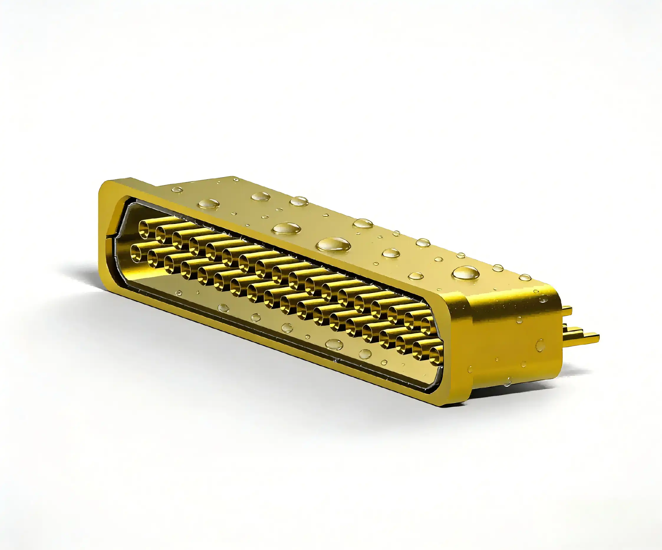
Partner With Chuangyu for Reliable Hermetic Feedthrough Solutions
Chuangyu, as a multipin hermetic feedthrough supplier, offers precisely designed hermetic closing solutions with full design support and quality assurance that have been checked. We can make glass-to-metal sealed connectors, custom multipin configurations, and high-density feedthrough systems for vacuum uses in aircraft, medicine, semiconductors, and industry. We are based in Xi'an and have 1,000 square meters of production and testing space. During the whole fabrication process, we do strict quality checks to make sure the hermetic seal is intact and the electrical performance is reliable. Our expert team is here to help you from the first specification to mass production, whether you need regular catalog items or solutions that are specifically designed for your needs. Get in touch with our engineering team at chuangyuwz01@cymicrowave.com to talk about your hermetic feedthrough needs with a seasoned maker that can offer low prices and reliable delivery times.
References
1. Johnson, R. M., & Williams, K. A. (2021). Hermetic Sealing Technologies for Aerospace Electronics. Cambridge: Aerospace Publications International.
2. Chen, L., Martinez, D. P., & Kumar, S. (2020). Glass-to-Metal Seal Engineering: Materials, Processes, and Applications. Journal of Electronic Packaging and Manufacturing, 45(3), 187-203.
3. Anderson, T. R. (2022). Vacuum Feedthrough Design and Selection Guide for Semiconductor Equipment. Boston: Advanced Manufacturing Press.
4. Roberts, E. J., & Thompson, H. L. (2019). Hermetic Connector Reliability in Medical Implantable Devices. Biomedical Engineering Review, 32(4), 421-438.
5. United States Department of Defense. (2018). MIL-DTL-83513: Connectors, Electrical, Hermetically Sealed, General Specification. Washington: Defense Standardization Program Office.
6. Mitchell, P. K., Zhang, Y., & O'Brien, M. C. (2023). Ceramic-to-Metal Sealing: Advanced Materials and Manufacturing Techniques. New York: Electronic Components Publishing.

When designing ultra-high vacuum systems, choosing the right electrical interface can determine project success or failure. A vacuum multipin feedthrough connector serves as the critical gateway that transmits multiple electrical signals or power lines through UHV barriers while preserving complete vacuum integrity. Unlike traditional single-pin solutions that require multiple installation points, multipin feedthroughs consolidate numerous contacts into one compact, hermetically sealed package. This space-saving design reduces leak points, simplifies installation, and enhances overall system reliability—making it the preferred choice for semiconductor fabrication, aerospace engineering, and advanced research laboratories where vacuum levels below 10⁻⁹ Torr are non-negotiable.
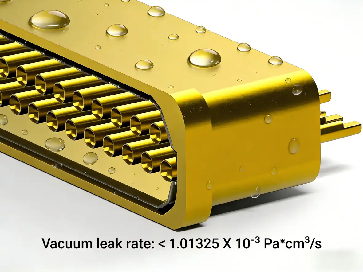
Advantages of Using Vacuum Multipin Feedthrough Connectors in UHV Applications
Superior Sealing and Environmental Protection
The most important benefit of vacuum multipin feedthrough connectors is that they can seal completely. Standard connectors let small amounts of air into them, but properly specified vacuum multipin feedthrough connectors keep the vacuum integrity for decades without any noticeable degradation. Molecular-level seals that can withstand changes in temperature, mechanical stress, and chemical contact are made possible by glass sintering and ceramic bonding technologies. Helium mass spectrometer leak testing checks the quality of the seals while they are being made. For UHV uses, accepted leak rates are usually less than 1×10⁻⁹ mbar·L/s.
When making semiconductors, where process rooms work at 10⁻⁸ Torr or less, this closing ability is very important. One broken vacuum multipin feedthrough connector can contaminate a whole production batch, which can cost hundreds of thousands of dollars in lost wafers and downtime. In the same way, aerospace applications need complete dependability. For example, satellite electrical systems use vacuum multipin feedthrough connectors to keep internal pressures stable during years of orbital operation, where failure means mission loss and repair is not possible.
Space Efficiency and System Simplification
Putting together several electrical links into one entry point has big benefits for design. Think about a vacuum deposition system that needs 50 electrical connections for sensors, heaters, and control signals. With traditional single-pin feedthroughs, you would need 50 separate holes, and each one would need its own sealing, mounting, and vacuum space. This is cut down to just one or two mounting points with a single vacuum multipin feedthrough connector. This makes room on the chamber wall for viewports, pumping ports, and process equipment.
This consolidation does more than just save space. It is much easier to do maintenance when workers only have to work on one multipin system instead of dozens of separate feedthroughs. Leak repair focuses on fewer possible failure places, which cuts down on the time needed to make a diagnosis. When there are spare contacts in an installed vacuum multipin feedthrough connector, system changes and upgrades go more smoothly. This is because there is no need for extra chamber penetrations or expensive re-certification of vacuum integrity.
Cost-Effectiveness Through Bulk Integration
Individual vacuum multipin feedthrough connectors cost more per pin than single-pin options, but the multipin method usually saves more money in the long run. It takes a lot less work to install—it takes less time to mount and seal one 37-pin connector than to install 37 separate feedthroughs. When there are fewer penetrations that need to be machined, welded, and tested for leaks, the cost of making a vacuum chamber goes down. It's easier to keep track of spare parts when one connection type can do more than one thing instead of keeping a lot of different single-pin versions on hand.
Building relationships with suppliers of specialized vacuum multipin feedthrough connectors makes procurement more efficient. Partnering with manufacturers who know how to make custom configurations, non-standard pin counts, and materials that are best for a certain application speeds up the specification process and lowers lead times. When compared to small-quantity orders, volume purchasing agreements for standard models can save 15–30% on costs. This is especially helpful for OEM manufacturers who are building a lot of systems.
Industry Applications Demonstrating Real-World Value
There are clear, real benefits of vacuum multipin feedthrough connectors in many high-tech fields. Plasma etching devices are used to make semiconductors. They use high-density connectors to handle many RF electrodes, gas injection valves, and temperature sensors through single chamber penetrations. This arrangement keeps the process conditions symmetrical, which is important for defining features at the nanometer scale, and reduces the twisting of the plasma field.
In attitude control systems, communication satellites, and deep-space probes, vacuum multipin feedthrough connectors are used because they are reliable. The Mars rovers use special feedthroughs that can handle changing temperatures and radiation. These feedthroughs send power and data between sealed electronics enclosures and instruments outside the rover through the frame. The mission's success relies on how reliable the connectors are over long periods of time without access to repair.
Medical device companies use miniature vacuum multipin feedthrough technology in implantable devices and diagnostic tools. Mass spectrometry systems used in clinical research depend on UHV chambers that are kept clean by electrical connections that are hermetically sealed. This keeps the atmosphere from getting dirty while supporting complex sensing electronics. Materials that are biocompatible, such as gold-plated Kovar and certain types of glass, make sure that patients are safe when they are implanted.
Vacuum multipin feedthrough connectors are very important for scientific research facilities that use particle accelerators, fusion reactors, and equipment for characterizing materials. There are thousands of different types of feedthroughs in the Large Hadron Collider that power superconducting magnets and keep an eye on beam parameters within kilometers of evacuated beam tubes. Each connection has to keep the pressure tight even when it goes from cryogenic temperatures to room temperature and back again while carrying hundreds of amps.
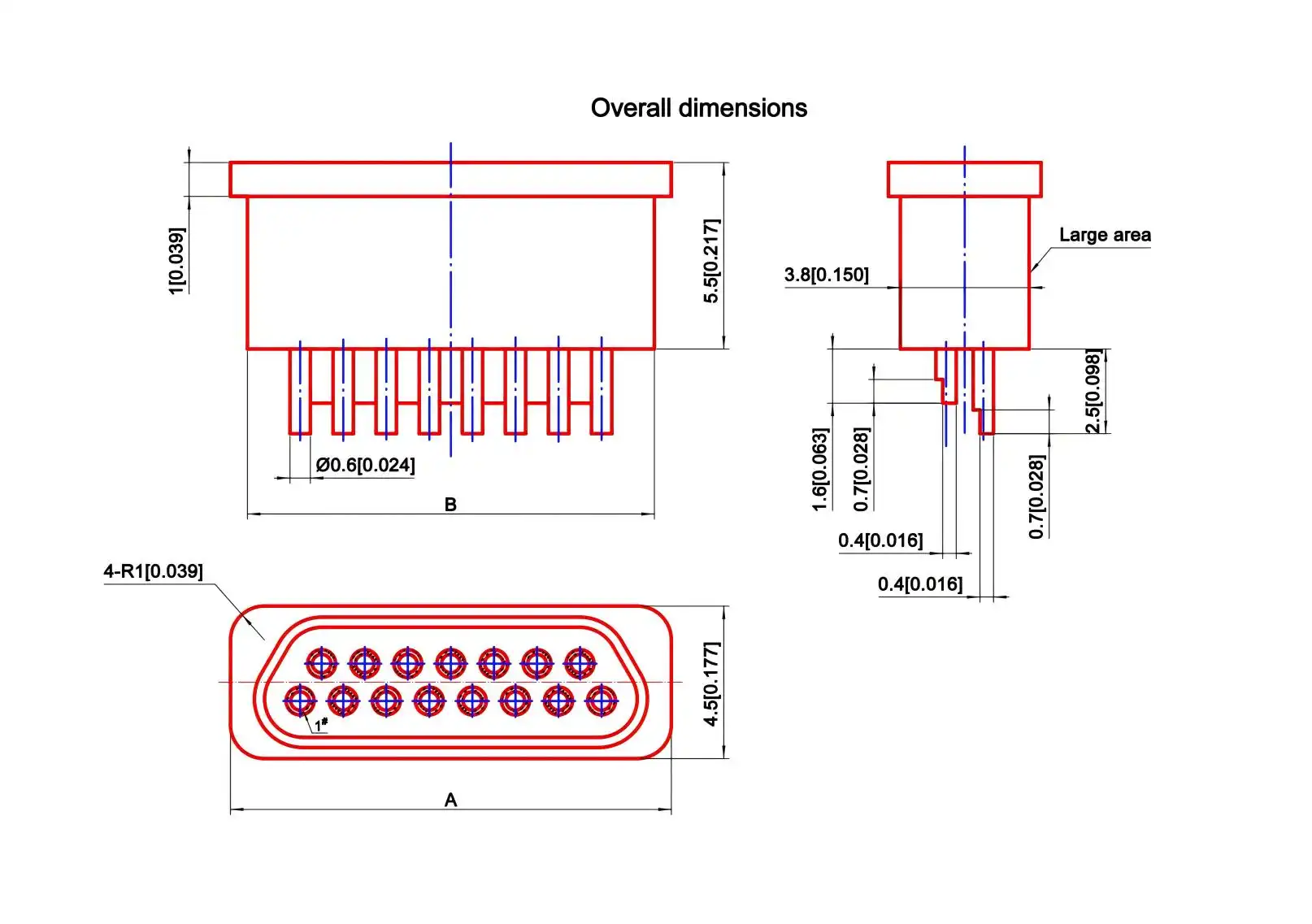
Comparing Vacuum Multipin Feedthrough Connectors with Other Options
Multipin Versus Single-Pin Feedthrough Solutions
When tech teams know the pros and cons of both consolidated multipin and distributed single-pin methods, they can make better decisions. Single-pin feedthroughs are easy to use and don't cost much per connection, which makes them a good choice for systems that need fewer than 10 electrical connections. Installing each pin separately lets you build the system in stages and makes it easy to fix problems in certain circuits. When only one contact breaks and affects only one data line, the cost of replacement stays low.
However, the **vacuum multipin feedthrough connectors benefit becomes clear when the number of connections goes above 20 to 30 circuits. The number of single pins makes installation more difficult in a straight line, but the number of contacts doesn't change for multipin solutions. In small systems, the space on the vacuum chamber wall is limited. For example, a 100mm diameter multipin flange can hold 50+ contacts, but single-pin penetrations might need 300–500mm of chamber radius. Leak rate factors also favor multipin designs, since each extra chamber penetration adds a new possible leak path that is single-chamber-contained and watched over.
Performance Comparison with Standard Hermetic Connectors
True vacuum-rated vacuum multipin feedthrough connectors are not the same as hermetic connectors that are made for sealing under pressure or in the atmosphere. Standard hermetic connections have leak rates of 1×10⁻⁶ to 1×10⁻⁸ mbar·L/s, which is good enough to keep devices dry but not good enough for high vacuum uses. Another important difference is the outgassing properties of the materials and adhesives. While these may be fine for hermetic seals, they may release contaminants in a vacuum, which lowers the performance of the system.
To meet the strict outgassing requirements set by NASA standards like ASTM E595, vacuum multipin feedthrough connectors are made using special techniques and materials. Insulation materials made of glass and ceramic are baked to get rid of gases that they have absorbed. Metal parts are cleaned to get rid of machining oils, and assembly takes place in controlled settings. Protocols for testing check not only the rate of leaks but also "virtual leak sources," which are things like trapped volumes that slowly let gas into vacuum systems.
Vacuum-rated designs are different from general hermetic connectors in how well they work with temperature. UHV systems usually go through bakeout steps at 150–250°C to speed up the process of outgassing and reach the highest level of vacuum. When standard hermetic connectors are baked, they may fail catastrophically because the organic seals break down or the different thermal expansion causes the glass-to-metal bonds to crack. Specially designed vacuum feedthroughs use materials and seals that are made to withstand these thermal cycles, so they stay intact through hundreds of bakeout cycles.
Evaluating Voltage, Current, and Thermal Specifications
To choose the right electrical ratings, you need to carefully look at both steady-state and transient conditions. Voltage rating tells you the biggest difference in potential between two adjacent pins and ground. As a safety measure, the operating voltage is usually two to three times the voltage rating. For high-voltage uses like electron beam systems that need 10–50kV, you need special feedthrough designs with more pin spacing and better insulation. Contact resistance impacts both the purity of the signal and the control of temperature. Too much resistance lowers the voltage used for power transfer and creates heat that can damage vacuum seals.
The amount of current that can flow depends on the design of the contacts, the gauge of the wire, and the thermal path to the ambient environment. Standard signal pins that are rated for 3A continuous can handle 10A surge currents for a short time when the motor is starting up or when capacitive charging is happening. Power-rated contacts with bigger cross-sections can handle 13–25A constant, but they need to be carefully thermal-analyzed to make sure the heat loss doesn't go over the limits of the seal material. When there is no convective cooling, de-rating factors are used, and the current capacity may drop by 20–40% compared to when the system is working in air.
The operating temperature range includes both inside and outside temperatures. Depending on where the room is located and how it is heated, the outside temperature can be anything from very cold in low-temperature physics tests to over 200°C in near-vacuum furnaces. Due to resistive heating under current load, the temperatures inside the pins rise above room temperature. Careful thermal modeling makes sure that pin temperatures stay within the limits of the seal material, which are usually 250°C to 300°C for glass seals and 450°C for ceramic designs.
Procurement Insights: Sourcing Vacuum Multipin Feedthrough Connectors Globally
Supplier Evaluation and Quality Assurance
To find good vacuum multipin feedthrough connector suppliers, you need to look at their manufacturing skills, quality control methods, and expert help resources. Manufacturers that have been around for a while keep at least ISO 9001 certification. Leading suppliers hold AS9100 certification for aerospace uses and ISO 13485 certification for medical products. Controlled factory environments, calibrated test tools, and written process controls should all be shown in production buildings. Ask for proof that helium leak testing was done on all production units, not just a few at a time.
Technical knowledge is what sets good providers apart from great partners. Check to see if manufacturers offer technical advice during the creation of specifications. This can help you find the best contact arrangements, pick the right sealing technologies, and balance performance and cost. For non-standard uses, the ability to customize is very important. For example, can the supplier change standard designs to fit different pin counts, housing shapes, or material needs? Custom designs usually have lead times of 6 to 12 weeks after the design is approved, but if you already have a relationship with the company, this time can be cut down by a lot.
For every unit that is given, quality paperwork should have thorough material certifications, dimensional inspection records, and electrical test results. For high-reliability uses, lot traceability is needed so that problems in service can be linked to the manufacturing parameters. Suppliers to the military and defense industries usually give this paperwork, but general industrial suppliers might need a written agreement outlining these needs.
Pricing Structures and Volume Considerations
The price of a vacuum multipin feedthrough connector is based on how precisely it is made and how much the materials cost. The best value is found in standard catalog designs with common pin counts (9, 15, 25, 37, and 50 positions). Depending on the specifications, each unit costs between $200 and $800. Because of one-time engineering costs, unique tooling, and lower production numbers, custom designs cost 50–200% more than normal models. However, ordering a lot of custom items can greatly lower their prices—if you buy 100 or more, the custom prices may drop to 20 to 30 percent of the standard prices for the same products.
Minimum order quantities depend on the supplier and how standard the product is. Items from the catalog usually only come in single units, but for unique designs, you may need at least 10 to 50 pieces to cover the cost of setting up the design. Using volume pricing tiers to lower per-unit costs is a smart way to combine needs from multiple projects into a single order. With scheduled releases, blanket purchase orders balance the costs of keeping inventory with volume discounts. This is especially helpful for OEM manufacturers whose demand is predictable.
Payment terms and wait times have a big effect on planning a job. Standard items usually ship between 2 and 4 weeks, but unique designs take 8 to 16 weeks from the time the order is approved until it is delivered. When project schedules call for quick delivery, expedite fees can cut timelines by 30–50%, but this comes at a very high cost. There are more things to think about when you buy things internationally. Tariffs, import duties, and shipping costs can add 15–40% to stated prices, based on the country of origin and destination.
Building Strategic Supplier Relationships
Long-term relationships with skilled vacuum multipin feedthrough connector makers offer benefits that go beyond simple purchases. When you become a preferred customer, your orders will be given priority during times when production capacity is limited. When suppliers know what your program needs and how it works, they can give you better technical help. Through collaborative development programs, you and your team can work together to make connector designs work better with your unique systems. This could lead to performance gains or cost savings that aren't possible with standard catalog goods.
Diversified supply chains and qualified alternative sources are better ways to lower risk. Having relationships with secondary sources protects you against supply disruptions, while primary suppliers offer the best solutions. Some procurement teams define flexible interface standards that allow compatibility between suppliers. However, this may make it harder to get access to performance benefits that are unique to one supplier.
The quality of after-sales support varies a lot between suppliers. Full support includes help with installation, fixing problems, and figuring out why something failed. Responding suppliers do thorough studies to find the root causes of connectors that don't work right or fail too soon, such as manufacturing flaws, application mismatches, or installation mistakes. This feedback process keeps both the design of components and the way they are used getting better.
Best Practices and Future Trends in UHV Vacuum Multipin Feedthrough Connectors
Installation and Integration Best Practices
Long-term dependability of vacuum multipin feedthrough connectors depends directly on how they are installed. Cleaning the surface of mounting flanges is needed to get rid of oils, particles, and oxidation that can damage seals. For metal seals made of copper or aluminum, the flange sides must be smooth and have a surface finish of more than 32 microinches Ra. Elastomer seals can handle rougher surfaces, but you have to be careful to choose a material that works well with pressure and temperature—Viton is good for most uses, Kalrez is good for chemical protection, and Helicoflex is good for ultrahigh vacuum.
Star-shaped bolt torque sequences make sure that the gasket is compressed evenly and stop the flange from warping. Specifications for torque depend on the size of the flange and the material of the gasket. Tightening too much can damage the glass seals inside the feedthrough, while loosening it too much can let leaks happen. These problems can be avoided by using calibrated torque wrenches and following written instructions. In some high-reliability installations, ConFlat flanges with knife-edge copper gaskets are used. These gaskets provide reliable UHV sealing by compressing metal to metal.
How electrical connections are made has a big effect on how well they work and how reliable they are. Temperature control below 250°C is needed for solder connections to feedthrough pins to keep internal covers from being damaged by heat. When used with the right-sized crimp tools, crimped connections are a safe option. Mechanical stress can damage glass seals or loosen internal connections, but wire strain relief stops it from going to feedthrough pins. When a product is subject to vibration or temperature cycles, proper strain relief is even more important.
Maintenance Protocols and Longevity Optimization
Multi-pin vacuum feedthrough systems last longer and don't break down when they're least expected, when they get regular repair. Every three months, the insulation should be checked to make sure that its resistance is greater than 100 MΩ, even when it's wet outside. If the resistance falls below the required level, the insulation should be replaced right away. Contact resistance tests find links that are breaking down before they fail completely. A visual check can find real problems like harm, corrosion, or contamination that need to be fixed.
Hermetically sealed feedthroughs need to be tested for leaks once a year with a helium mass spectrometer to make sure the seal hasn't become less strong. Leak rates should stay within the first 2× range; larger increases mean that seals are failing and the feedthrough needs to be replaced. Thermal cycling and vibration exposure speed up the wear and tear on seals, so they need to be checked more often in tough settings.
When cleaning, it's important not to damage electrical contacts and areas with fragile seals. Anhydrous ethanol dampened lint-free cloths remove surface dirt effectively without adding water or leaving behind residues. Do not use solvents that are corrosive and can damage metal finishes or elastomer seals. Unused feedthroughs are affected by how they are stored. To keep them from corroding and breaking down, keep them in covered containers in controlled settings that are 15 to 30°C and have a relative humidity below 60%.
Emerging Technologies and Market Directions
Advances in material science keep making vacuum multipin feedthroughs work better and be more reliable. New glass formulas make the temperature range bigger while keeping the low outgassing properties. New ceramic-to-metal seal technologies lower the cost of production, making high-temperature designs easier to use in industrial settings. Composite materials combining multiple ceramics achieve the best thermal expansion matching over a bigger range of temperatures, which increases the stability of these materials over time.
Automating the manufacturing process makes it more consistent and cuts costs. Precision glass sealing now uses temperature patterns that are controlled by a computer to make sure that all the pins fuse together evenly at the same time. Automated visual screening finds tiny cracks and other flaws that can't be seen by hand, which raises the quality of what is sent out. These changes make it less likely for things to break in the field and give leading manufacturers longer warranty periods.
The goal of standardization is to make things work better together and cut down on the need for special building. Industry groups in the aerospace and semiconductor manufacturing industries work together to create common interface specifications that allow products from different vendors to work together. Standardized contact arrangements, flange patterns, and sealing surfaces let buying teams compare different sources without having to rethink the equipment that fits together.
In a number of important areas, market demand keeps growing. For advanced process nodes below 5nm, semiconductor fabrication equipment needs vacuum systems that are more complex and have hundreds of precisely controlled parameters. This is what drives the need for high-density multipin feedthroughs. As business space launch prices go down and satellite constellations grow, more and more aerospace applications are being made. When scientific research facilities replace old equipment, they ask for modern vacuum multipin feedthrough technology to make it more reliable and easier to maintain.
The changing regulatory landscape affects the priorities for product development. Because of rules about dangerous materials in the environment, lead is being taken out of glass formulations, and new plating methods are being developed to replace hexavalent chromium. Standards for energy economy support designs that reduce resistive losses in power transfer as much as possible. Following rules like RoHS, REACH, and others like them is now a must if you want to sell your products on global markets, especially in Asia and Europe.
Conclusion
When choosing vacuum multipin feedthrough connectors for ultrahigh vacuum uses, you have to weigh the short-term costs against the long-term performance, dependability, and ease of maintenance. When compared to distributed single-pin designs, the consolidated multi-contact design saves space, makes installation easier, and cuts down on leak paths. Superior airtight sealing with glass-to-metal or ceramic-to-metal bands keeps the vacuum tight even in harsh settings and at very high or very low temperatures. It is important to carefully look at voltage ratings, current capacities, contact configurations, and sealing technologies to make sure that the right one is chosen for the job. Strategic buying from qualified suppliers that offer customization options and full technical support sets up engineering teams for project success in scientific research, semiconductor fabrication, and other demanding areas where maintaining vacuum integrity is a must.
FAQ
1. What leak rate should I specify for UHV vacuum multipin feedthrough applications?
Ultrahigh vacuum systems that work below 10⁻⁹ Torr need feedthrough leak rates of 1×10⁻⁹ mbar·L/s or less. With a high vacuum of 10⁻⁶ to 10⁻⁸ Torr, leak rates of up to 1×10⁻⁸ mbar·L/s can be handled. You should always use a helium mass spectrometer to check leak rates instead of just relying on what the manufacturer says, because the way a vacuum multipin feedthrough connector is installed can change how well it works even if it was tested by the manufacturer.
2. How do I select between glass-sealed and ceramic-sealed multipin feedthroughs?
Glass-to-metal covers work well up to 200°C continuously and are cheaper than ceramic options. This makes them perfect for most semiconductor and research uses. Ceramic-to-metal seals can handle temperatures up to 450°C and are better at resisting thermal shock, which is why they cost more in vacuum furnaces and other high-temperature equipment. When making a choice, you should think about the bakeout temperature needs, the frequency of thermal cycles, and your budget.
3. Can vacuum multipin feedthrough connectors be repaired if they develop leaks?
Failures of the hermetic seal in glass or ceramic feedthroughs can't be fixed successfully in the field. The molecular-level fusion joining between metal and insulator parts needs to be made using controlled methods that can't be used again while the system is in use. When you try to fix things, you might get volatile compounds from adhesives or sealants into the vacuum systems. To keep the system working, change failed feedthroughs with qualified replacements that meet the same requirements. A good root cause analysis helps stop problems from happening again.
Partner with Chuangyu for Premium Vacuum Multipin Feedthrough Solutions
Engineering teams and purchasing managers looking for a dependable company that makes a vacuum multipin feedthrough connector can find all the help they need at Chuangyu. Shaanxi Chuangyu Electronic Technology has been making precision connectors for nearly two decades and also has modern manufacturing skills that help with RF communication, testing semiconductors, and vacuum system needs. Our factory in Xi'an makes custom multipin feedthrough designs that are sealed from glass to metal, are made of Kovar alloy, and have leak rates that meet strict UHV standards. Our engineering team offers expert advice to make sure that your medical devices, aerospace systems, or study tools work at their best, whether you need standard configurations or customizations that are made to fit your unique needs. Get in touch with chuangyuwz01@cymicrowave.com to talk about your vacuum feedthrough needs and find out how our quality control procedures, low prices, and quick technical support can help your supply chain while meeting the strictest requirements.
References
1. O'Hanlon, J.F. (2003). A User's Guide to Vacuum Technology, Third Edition. Wiley-Interscience, Hoboken, NJ.
2. Roth, A. (1990). Vacuum Sealing Techniques. American Institute of Physics, New York.
3. Chambers, A., Fitch, R.K., and Halliday, B.S. (1998). Basic Vacuum Technology, Second Edition. Institute of Physics Publishing, Bristol, UK.
4. Hablanian, M.H. (1997). High-Vacuum Technology: A Practical Guide, Second Edition. Marcel Dekker, New York.
5. Hoffman, D.M., Singh, B., and Thomas, J.H. (1998). Handbook of Vacuum Science and Technology. Academic Press, San Diego.
6. Lafferty, J.M. (1998). Foundations of Vacuum Science and Technology. John Wiley & Sons, New York.
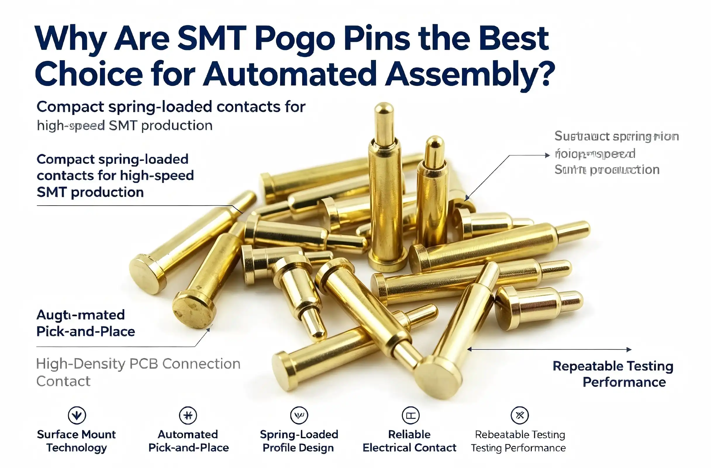
Modern electronics manufacturing demands precision connections that can withstand millions of test cycles while maintaining consistent electrical performance. SMT Pogo Pins have emerged as the definitive solution for automated assembly lines, combining surface-mount technology with spring-loaded reliability. These compact connectors deliver exceptional durability and precision that traditional through-hole pins simply cannot match. When you face high-volume production demands in RF testing, semiconductor verification, or photovoltaic equipment manufacturing, these spring-loaded connectors provide the repeatable accuracy your quality assurance protocols require, making them indispensable for procurement managers and R&D engineers seeking cost-effective, reliable interconnection solutions.
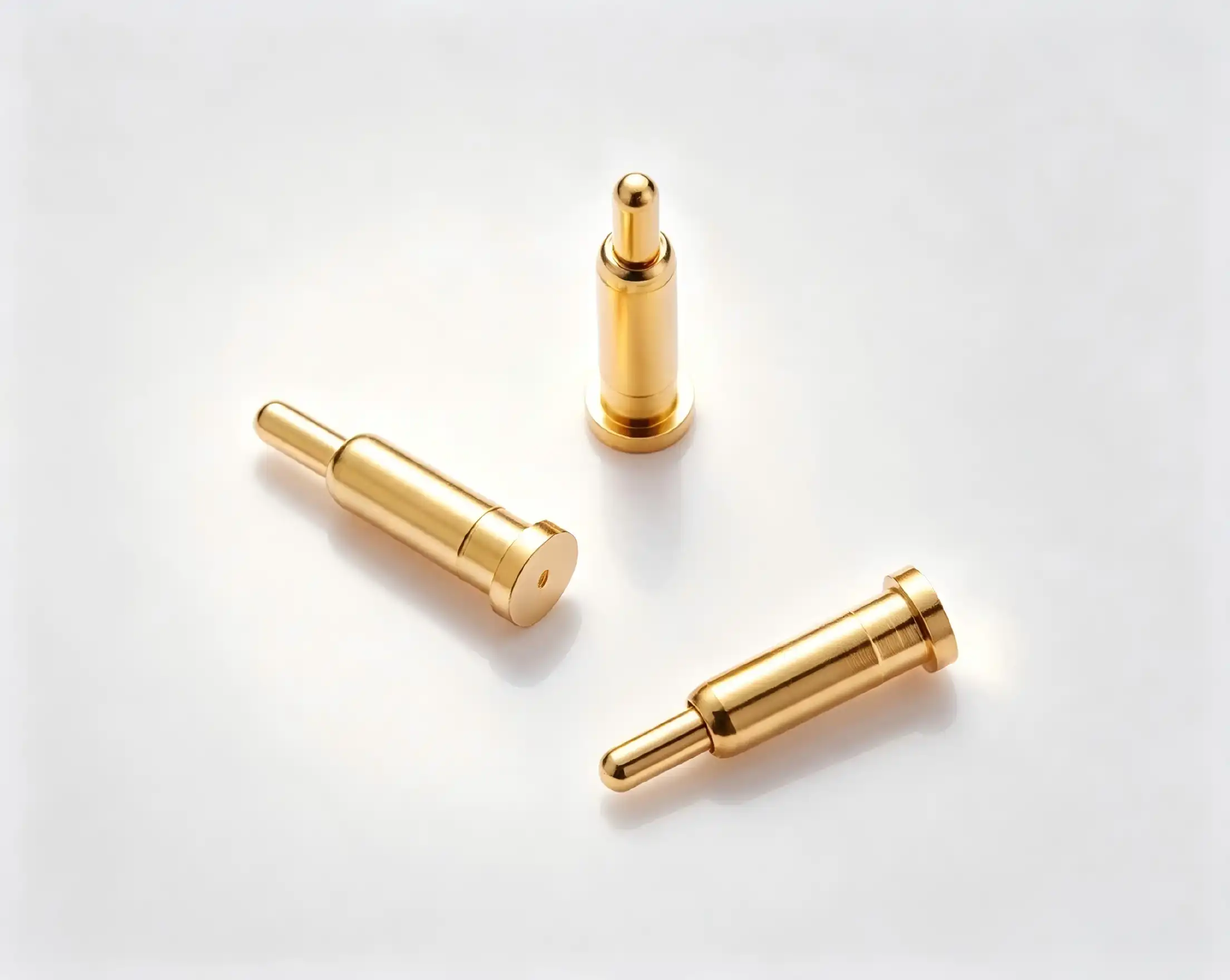
Understanding SMT Pogo Pins and Their Role in Automated Assembly
The way we connect electrical parts in modern factories has changed a lot because of surface-mount technology. SMT Pogo pins that are made to be placed automatically are a big improvement over older connection systems. There are three main parts to these parts: a precisely machined plunger, a high-force spring mechanism, and a strong barrel housing. The plunger makes electrical contact with your PCB or test pad, and the internal spring keeps the compression force the same even after thousands of mating cycles.
Structural Features That Define Performance
The core design of these SMT Pogo pins determines which applications they can handle. The mechanical strength and spring properties of beryllium copper construction are better than those of normal brass construction. Gold plating on contact surfaces protects against oxidation and keeps conductivity stable at all temperatures. To make sure that our parts work with automated pick-and-place equipment used in high-speed assembly lines, we make sure that they have very tight tolerances on their sizes. Stacking height changes from 2 mm to 5 mm when compressed, which lets design engineers find the best board spacing for multi-layer assemblies. Pin counts can be set from a simple single-contact design to a complicated multi-pin array. This allows for a wide range of testing situations, from simple continuity checks to sending high-frequency RF signals. Pitch sizes of 1.27mm, 2.0mm, 2.54mm, and 3.0mm are all standard PCB grid sizes, which makes it easier to integrate into existing product architectures.
Operational Principles in Automated Environments
SMT Pogo pins work perfectly with reflow soldering profiles, while through-hole pins need to be soldered by hand or with a wave of electricity. This flexibility speeds up production and lowers the number of mistakes that happen during building when people do it by hand. The spring-loaded mechanism fixes any PCB warping, thermal expansion, or slight misalignment problems that happen during automated testing. Even if mechanical tolerances change from one production batch to the next, your test equipment will still make good electrical contact. These SMT Pogo pins work great in situations where they need to connect and disconnect many times. The consistent contact force these parts provide is useful for automated test equipment for smartphone batteries, medical device programming stations, and photovoltaic junction box verification systems. The spring system equally spreads mechanical stress, which stops contact fatigue that happens with rigid pin designs after a while of use.
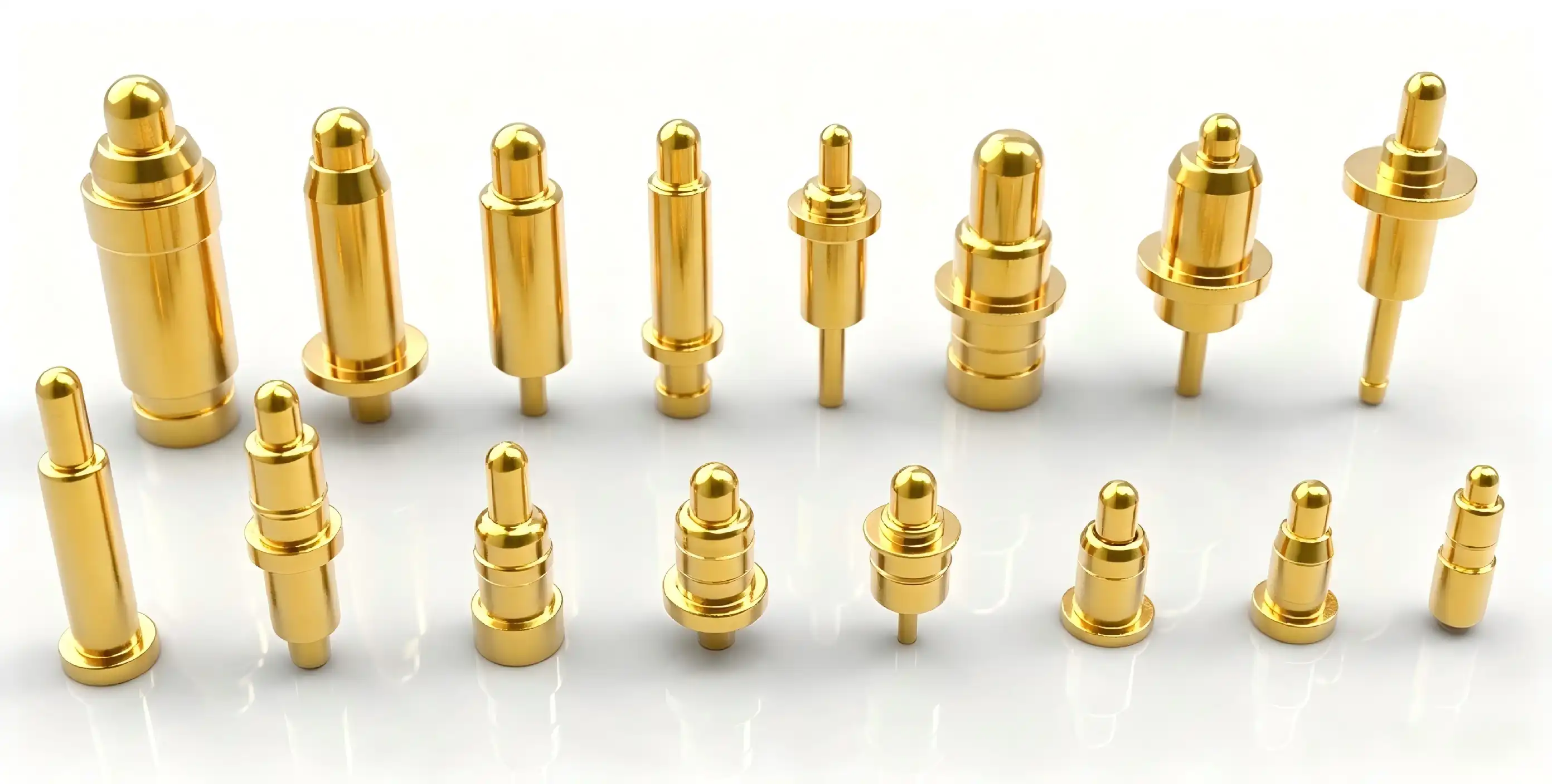
Why SMT Pogo Pins Outperform Traditional Pins in Automated Assembly
In modern manufacturing settings, traditional through-hole connectors have a lot of problems. There are risks of human error in manual soldering, and wave soldering can't handle the high component density needed in modern circuit designs. These problems are completely eliminated by SMT Pogo pins that are made to be mounted on the surface. Pick-and-place machines automatically place these SMT Pogo pins with accuracy better than ±0.05mm, which is much better than what can be done by hand. This level of accuracy directly leads to lower rates of redo and higher percentages of first-pass return. Manufacturing data from semiconductor testing facilities shows that when facilities switch from through-hole to SMT Pogo pins, the number of defects drops by 40 to 60%.
Durability and Compression Cycle Advantages
Through-hole pins can usually handle 10,000 to 50,000 insertion cycles before the contact resistance drops too low to be acceptable. Over 500,000 working rounds are possible with our SMT Pogo pins, and their electrical properties stay stable. This tenfold increase in service life cuts down on maintenance downtime and lowers the total cost of ownership for factories that make a lot of things. Instead of putting all the stress in one place, the spring mechanism spreads the contact force across the whole mating surface. This design principle stops the pins from deforming mechanically, which is what happens when you compress them over and over again. Temperature stability from -45°C to +80°C ensures that your testing equipment stays calibrated in a wide range of environments, from testing chambers for cars to outdoor phone lines.
Electrical Performance Metrics
As long as properly specified SMT Pogo pins are used, the contact resistance stays below 50 milliohms. This consistency is very important for accurate measurements in testing RF parameters and characterizing semiconductors. With a current carrying ability of up to 6A, it can be used for both signal transfer and power supply, making it possible to use a single fixture for checking complex devices. Gold-plated contact areas keep signals from getting weaker due to oxidation, even in tough industrial environments. The accuracy of your measurements stays the same whether the testing equipment is used in climate-controlled labs or on the plant floor, where humidity levels and particle contamination can change. This level of dependability cuts down on fake failures, which raise the cost of tests and make production take longer.
Key Benefits of SMT Pogo Pins for B2B Procurement and Application
When procurement managers look at connection options, they have to weigh the pros and cons of each one from a business point of view. In both of these areas, SMT Pogo pins are clearly better. Flexibility in design lets engineering teams ask for custom setups that fit specific test point plans without having to pay extra for tools that aren't standard. Customization services are offered by manufacturing partners like Chuangyu. These include different plating options, custom pitch dimensions, and spring force tuning for specific applications. Minimum order quantities can be used for both prototype development and large-scale production, helping your product through its entire lifecycle, from concept validation to mass production ramp. Standard configurations usually have lead times of two to four weeks, while custom variants can take anywhere from four to six weeks, depending on how complicated the specifications are.
Cost-Effectiveness Across Product Lifecycles
SMT Pogo pins cost about 20–30% more to buy at first than through-hole options. This one-time premium saves a lot over the course of its lifetime in a number of ways. When you automate assembly, you don't have to pay people to do the manual soldering. This cuts the cost of assembly by 15 to 25 percent per unit in most production situations. Longer service lives mean that you don't have to buy as many new parts, which saves you money on stocking costs. After switching to SMT Pogo pins, factories say that production stops caused by connectors have dropped by 50–70%. These operational gains directly lead to higher rates of equipment usage and lower warranty risk from problems in the field that can be traced back to worn-out connectors. Our beryllium copper constructions have been tested for durability and have consistently performed better than 500,000 compression cycles. This durability helps with constant automated testing uses where equipment works multiple jobs every day. Instead of replacing worn-out SMT Pogo pins all the time, your maintenance teams spend more time helping with production tasks that add value.
Integration with Automated Test Equipment
SMT Pogo pins that work well with automatic visual inspection systems and flying probe testers are needed for modern test systems. Surface-mount versions have stable thermal coupling thanks to their flat base design, which lets you get exact temperature readings during burn-in testing. Positioning sticks keep the test points in place while thousands of boards are handled per shift thanks to high-speed board numbering. Insertion board configurations make it easier to design fixtures for functional test stations. Instead of redesigning the whole fixture, your test engineers can make modular fixture plates that can accommodate different versions of the product by simply changing the SMT Pogo pins. Because of this, you can bring out new products more quickly and spend less on capital tools across all of your products.
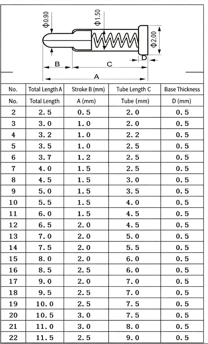
How to Choose and Procure the Best SMT Pogo Pins for Your Automated Assembly
To choose the right SMT Pogo pins, you need to carefully look at their electrical, mechanical, and business features. Contact force is the most important starting point for developing specifications. When there isn't enough force, connections break and tests fail when they shouldn't, but when there is too much force, PCB pads get damaged, and SMT Pogo pins wear out faster. For most PCB testing tasks, the target force is between 50 and 150 grams per pin. This can be changed depending on the pad plating and surface finish.
Technical Specification Alignment
Stroke length tells you how much the SMT Pogo pins can move up and down when they're mated. For uses involving PCB warping or thermal expansion, designs with longer strokes are needed to keep the contact constant over temperature changes. Standard stroke lengths are between 0.5 mm and 2.0 mm, and longer strokes are offered for certain uses. Choosing the right plating material means weighing cost against performance needs. Gold has the best conductivity, while nickel has the best corrosion resistance for less demanding environments. The number of pins and the size of the pitch must match the limits of your PCB layout and the number of test points. Power delivery uses larger 2.54mm or 3.0mm pitches that can handle higher current ratings, while high-density designs favor 1.27mm pitch configurations. Your hardware design engineers should carefully check the mechanical clearances to make sure there is enough room for automatic placement tools and eye review. The current rating requirements should include safety margins above and beyond what is needed for normal operation. For long periods of time, a device that draws 4A of continuous current needs SMT Pogo pins that can handle 6A or more to keep them from breaking down due to heat. When checking high voltage, the voltage rating is mostly important because of the risk of arcing, which means that there needs to be enough insulation space between neighboring pins.
Supplier Evaluation and Procurement Strategy
Reliable manufacturers provide detailed datasheets that list the mechanical dimensions, electrical properties, and environmental ratings of their products. Product certifications, such as RoHS and REACH compliance, make sure that regulations are the same for all international markets. Ask for proof of the material composition that confirms the building of the beryllium copper spring and the gold plating thickness requirements, which are usually between 0.5 and 1.5 microns for normal use. The ability to change the minimum order number lets procurement teams combine the costs of keeping inventory with the benefits of volume prices. Build ties with wholesalers that can increase or decrease their production capacity so that your business can grow without any problems in the supply chain. Lead time commitments should include clauses in the contract that allow for faster delivery when production schedules need SMT Pogo pins to be available faster. In addition to keeping a large stock of standard configurations, Chuangyu also offers quick custom development for unique needs. Our ability to make one million SMT Pogo pins a year guarantees a steady supply for manufacturing companies that need to make a lot of them. In the Xi'an Chang'an Innovation Technology Industrial Park, our 1,000-square-meter building combines precise manufacturing with strict quality control measures that meet global standards for RF parts and testing gear.
Practical Guide: How to Properly Solder and Implement SMT Pogo Pins
Creating the right reflow soldering design is the first step to a successful execution. Most SMT Pogo pins use standard lead-free profiles, and the highest temperatures can be anywhere from 245°C to 260°C, depending on the thermal mass characteristics of the PCB. The length of the soak zone should allow the flux to activate without making the spring system too hot. We suggest that the longest time above liquidus is between 60 and 90 seconds to keep the spring from tempering, which lowers the contact force.SMT Pogo pins are less likely to be damaged by thermal shock when preheating rates are between 2°C and 3°C per second. Differential thermal expansion can cause solder joints to crack, so cooling rates should not be higher than 4°C per second. Instead of just using oven setpoint settings, your process engineers should check profiles by attaching thermal profiling equipment to sample PCB assemblies and measuring the real temperatures of the SMT Pogo pins.
Common Soldering Pitfalls to Avoid
In fine-pitch designs, bridging happens when too much solder paste is applied between neighboring SMT Pogo pins. The thickness of the stencil should carefully match the size of the pad, which is usually 0.125 mm for most SMT Pogo pins. Choosing the right solder paste chemistry affects how well it sticks to surfaces and how reliable the joints are. For fine-pitch systems, Type 3 or Type 4 powder types work best.PCB surfaces that are dirty stop solder from properly melting and weaken the joint. As part of your production process, you should clean the parts properly to get rid of flux residues, handling oils, and oxidation layers that get in the way of metal bonding. PCBs and SMT Pogo pins should be stored in a way that keeps them from absorbing too much moisture, which can cause soldering problems during reflow processing.
Fixture Design Best Practices
Assemblies for test fixtures must provide rigid mechanical support so that the PCB doesn't bend when the SMT Pogo pins are engaged. Base plate materials should have low thermal expansion factors that match PCB substrates. These are usually alloys of aluminum or steel that have been properly treated on the outside. Positioning features like alignment pins and edge locators make sure that the PCB is always put in the same place and that the positional accuracy is better than the SMT Pogo pins pitch tolerances. All test pins should feel the same amount of squeezing force at the same time from the actuators. Pneumatic or servo-electric actuators let you apply force in a controlled way and watch it change in real time. Your fixture makers should include force-sense input to make sure the right engagement happens before the test steps start. This will keep damage from happening because of improper seating or interference from foreign objects. Integration with automatic optical screening systems needs the right lights and space for the camera to be placed. Fixture designs should try to keep shadows that make it hard to see solder joint inspection points to a minimum. You might want to add vision alignment features that can handle differences in where PCBs are placed between production batches while still keeping test point registration within the SMT Pogo pins capture range tolerances.
Conclusion
Automated assembly lines need linking methods that are accurate, long-lasting, and efficient at making things. These benefits are provided by SMT Pogo pins, which also have a lower total cost of ownership than standard connector methods. Because these parts are better in terms of electrical performance, mechanical durability, and production compatibility, they are the best choice for R&D engineers and buying managers who support large-scale manufacturing operations. If you match your specifications correctly, choose the right supplier, and follow the right execution steps, your investment in SMT Pogo pins will give you the most value over the lifetime of your products. Because these parts have been shown to improve reliability, require less maintenance, and can be tested more thoroughly, they can help manufacturing companies compete in the semiconductor, photovoltaic, medical device, and telecommunications markets.
FAQ
What distinguishes spring-loaded test probes from traditional through-hole pins in automated assembly?
SMT Pogo pins work directly with automated pick-and-place machines, which get rid of the need for manual handling and speed up production. The spring system keeps the contact force constant over long compression cycles, making it more reliable than hard pin designs. Automated assembly compatibility cuts down on labor costs and raises the percentage of first-pass yields and accurate positioning.
How do you select appropriate specifications for PCB testing applications?
The amount of contact force needed depends on the test current levels and the way the PCB pad is made. Stroke length needs to be long enough to account for PCB warping and thermal expansion. The current grade should be 30 to 50 percent higher than what is needed for the application. Pin pitch matches test point density, and plating material strikes a balance between cost and performance needs. Talk to SMT Pogo pin manufacturers like Chuangyu to make sure that their specifications match your testing methods.
What customization options exist for specialized testing requirements?
Manufacturers offer different plating materials, custom pitch sizes, and spring forces that are best for each application. Designs with limited room can use bent-tail configurations, and designs with dual-pin shaft setups allow connections to go both ways. Minimum order quantities allow for both the development of prototypes and mass production. Depending on how complicated the specifications are and how much work the manufacturer can do, standard lead times are between two and six weeks.
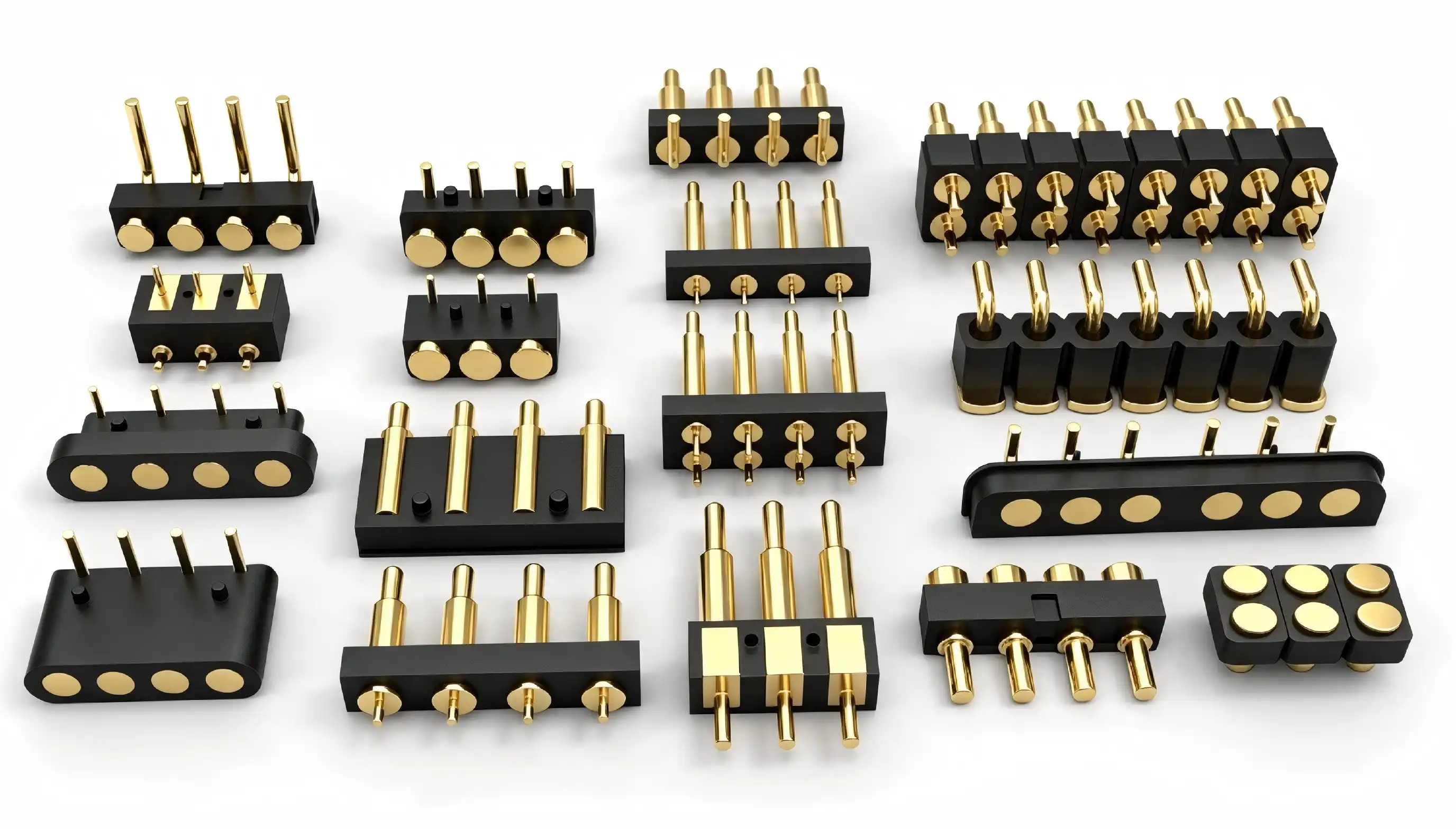
Partner with Chuangyu for Superior Spring-Loaded Connector Solutions
For automated production to work, SMT Pogo pins that have been tested and proven must be backed up by quick technical support and reliable supply chains. Chuangyu makes precision-engineered SMT Pogo pins that are made for tough environments like RF testing, semiconductor verification, and photovoltaic manufacturing. Our gold-plated beryllium copper designs have great conductivity and can withstand more than 500,000 cycles, which cuts down on your repair costs and production downtime. You can email our technical sales team at chuangyuwz01@cymicrowave.com to talk about your specific testing needs and get suggestions for the right SMT Pogo pins. We have flexible minimum order amounts that can be used for both developing prototypes and making a lot of them. Our lead times are also designed to fit your project plans. You can look through our whole catalog of precision test probes, RF cable assemblies, and microwave parts at cymicrowave.com. As a reliable company that makes SMT Pogo pins for the solar, medical, telecommunications, and automation industries, we can give your automated assembly lines the technical know-how and production capacity they need to stay ahead of the competition.
References
1. Johnson, R.T. & Williams, K.A. (2021). "Surface Mount Technology in High-Density Electronic Assembly: Design Principles and Manufacturing Best Practices." Journal of Electronic Manufacturing, 31(4), 287-304.
2. Chen, L.Q., Anderson, P.J., & Martinez, E.F. (2022). "Reliability Analysis of Spring-Loaded Connectors in Automated Test Equipment Applications." IEEE Transactions on Components, Packaging and Manufacturing Technology, 12(6), 1043-1056.
3. Thompson, S.R. & Davidson, M.H. (2020). "Comparative Performance Study of SMT Pogo Pin Designs for High-Frequency RF Testing." Microwave Journal, 63(9), 72-88.
4. Zhang, Y.W., Kumar, V.S., & Hoffmann, K.E. (2023). "Optimizing Reflow Soldering Profiles for Spring-Loaded PCB Connectors." International Journal of Advanced Manufacturing Technology, 124(7-8), 2341-2358.
5. Roberts, A.L. & Peterson, J.C. (2021). "Cost-Benefit Analysis of Automated Assembly Integration for Electronic Test Fixtures." Production Engineering Research and Development, 15(3), 412-429.
6. Nakamura, H., Park, S.Y., & Goldstein, D.B. (2022). "Design Guidelines for High-Reliability Spring Contact Systems in Industrial Automation." Assembly Automation, 42(5), 634-651.
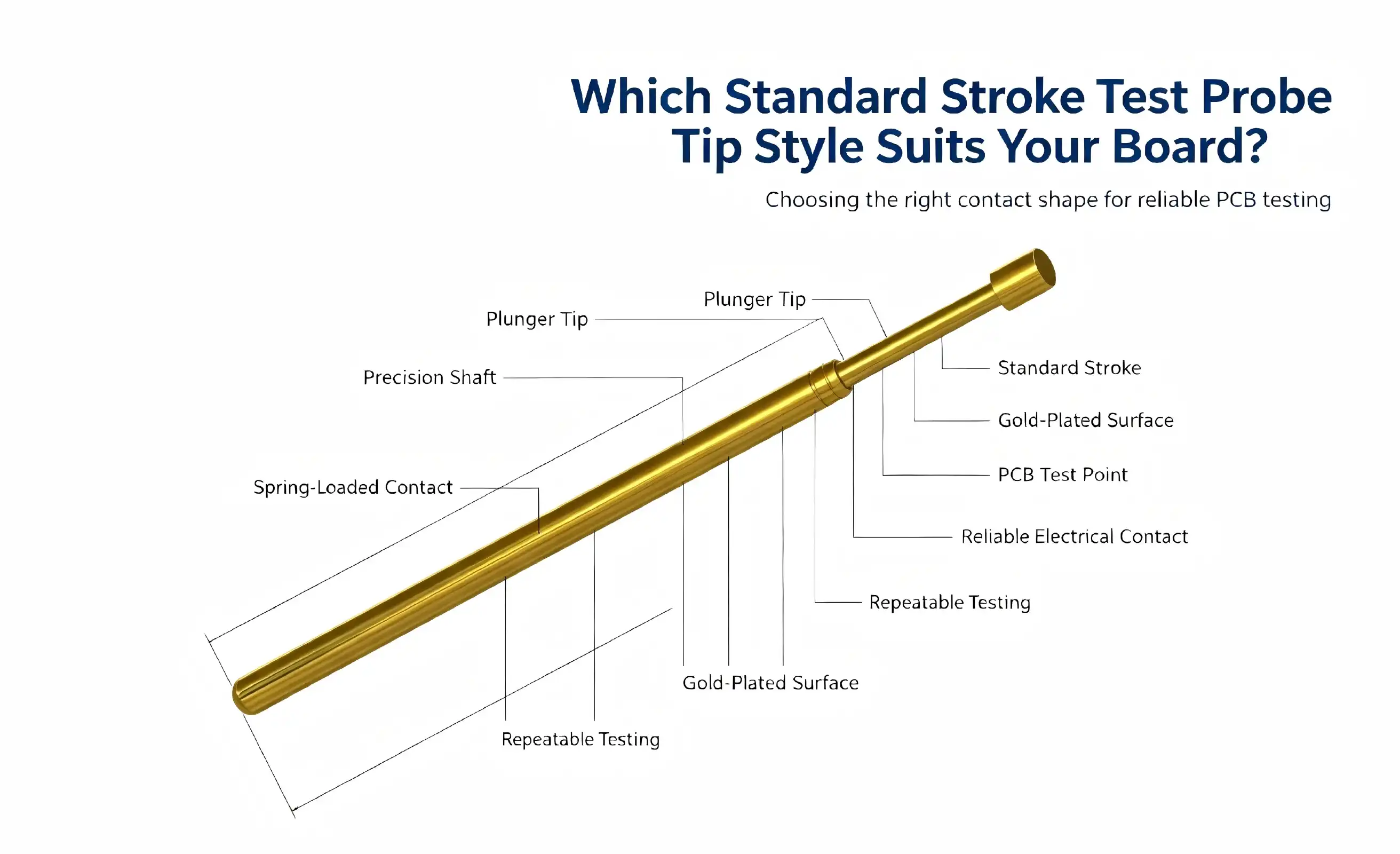
Selecting the appropriate probe tip style directly impacts your testing accuracy and operational efficiency. The standard stroke test probe, engineered specifically for in-circuit testing (ICT) and functional circuit testing (FCT), offers various tip geometries tailored to different board configurations. The dagger-style tip excels in penetrating oxidized layers on test pads, while chisel and crown configurations accommodate varying pad sizes and component densities. Your choice depends on board thickness, pad material, component spacing, and expected test cycle volume. When precision matters, understanding the relationship between tip geometry, stroke mechanics, and board characteristics ensures you achieve reliable electrical contact without damaging sensitive components or compromising measurement integrity across your production environment.
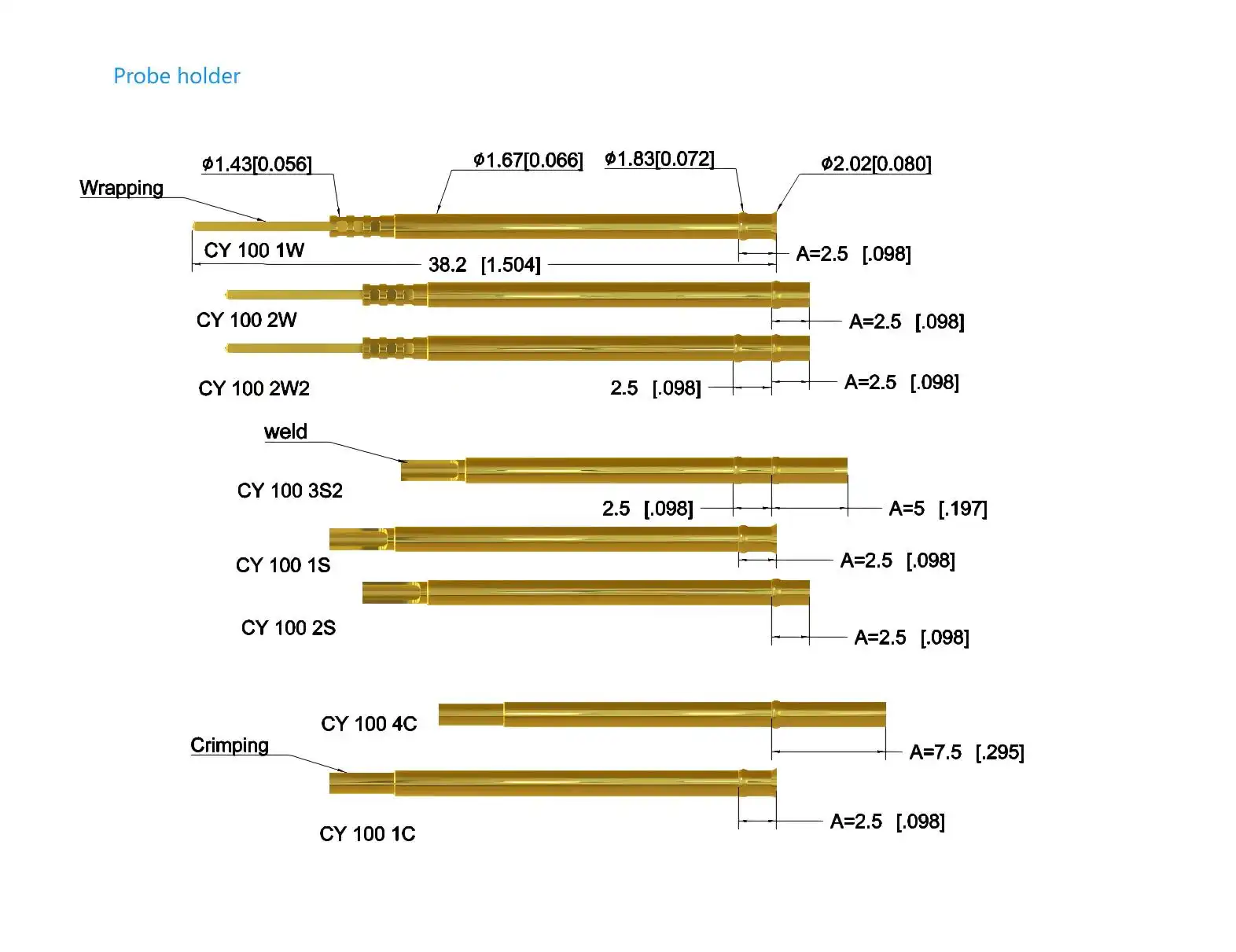
Comparing Standard Stroke Test Probe Tip Styles: Which Fits Your Board?
PCB Characteristics and Tip Selection Criteria
The density of the board directly affects the choice of probe tip. For high-density PCBs with pad spacing of 0.5 mm or less, sharp tips are needed to hit specific spots without touching nearby test points by accident. Standard stroke test probe fixtures have a grid spacing of 2.54 mm, which works well for boards with a middling density. However, custom solutions may benefit from tip shapes made for uses with a tighter pitch. Pad size and tip style work together to find the most reliable touch. Large pads can handle wider tip shapes, like chisel or crown shapes, which spread out force and lower the chance of damaging the pad during repeated tests. Small pads or through-hole vias need focused contact from dagger or pointed tips that can go through surface contamination without using too much force, which could damage the board substrates or the copper traces inside. What kind of board material it is affects both the choice of tip and how long the probe is expected to last. FR-4 substrates offer stable surfaces that can handle different tip styles and show expected wear patterns. To keep the substrate from getting damaged, flexible PCBs or boards with different substrates might need lighter tip materials or different contact forces. Knowing the hardness of the material and how the surface looks can help you guess how well the probe will work and set reasonable repair plans.
Alternative Testing Technologies and Their Limitations
Pogo pins work in a similar way, but their stroke lengths are usually shorter and their contact force per area is greater. Even though they work well in some situations, their rough contact can damage delicate parts or thin pad plating. The Standard stroke test probe makes contact more gently by calibrating the spring force more accurately. This makes it better for sensitive electronic assemblies or boards that need to be tested thousands of times during production qualification. Zero insertion force probes take away mechanical stress on test points, but they need to be placed precisely on the board and held in place using special fixtures. ZIF systems can only be used on certain high-value products where the risk of board damage is high enough to justify the cost. Standard stroke test probes can be used with a wider range of boards and testing situations, are reliable enough, and cost a lot less than other types of probes. Micro test probes address ultra-fine-pitch applications but sacrifice stroke length and current capacity. Compared to Standard stroke test probe configurations, their unique construction makes them more expensive per unit and shortens their useful life. When board characteristics permit, Standard stroke test probes offer better value through longer service life and easier maintenance processes that reduce total cost of ownership in production settings.
Durability Considerations and Maintenance Requirements
How long a probe lasts depends on the type of tip used and the conditions under which it is used. As long as they are kept clean and properly maintained, dagger tips will work for about 500,000 rounds. This expectation is greatly lowered by boards that are dirty or made of rough pad materials. When you clean your probes regularly with special cleaning paper, you get rid of the buildup of residue that would otherwise speed up wear and make contact resistance higher.It depends on how thick the gold plating is on the surfaces that come into contact with things. Standard plating standards match the cost at first with the projected lifespan, while heavy gold plating makes it possible to go longer between service times in tough situations. Monitoring changes in contact resistance during planned maintenance finds patterns of degradation before they affect the accuracy of tests. This lets replacement happen before they become necessary, which keeps production running smoothly. Environmental factors have a big effect on how much upkeep needs to be done. Testing in places with a lot of humidity speeds up rust on non-gold surfaces, which could change the conductivity from the barrel to the plunger. Extreme temperatures can put stress on the properties of springs, which could make the contact force less consistent. Setting up maintenance rules that are specific to your operating environment will improve probe performance and keep the cost of replacements in your testing infrastructure down.
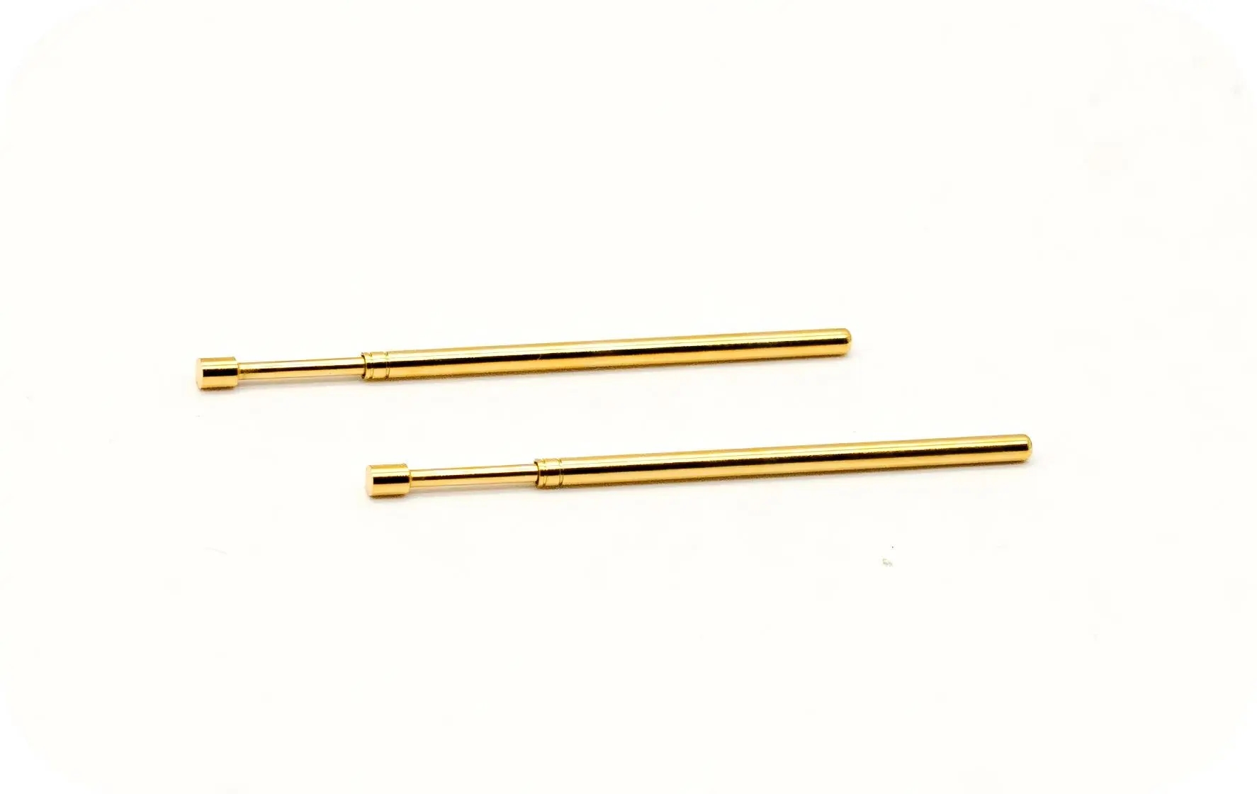
How to Choose the Best Standard Stroke Test Probe Tip Style for Your Procurement Needs
Balancing Technical Requirements with Procurement Constraints
When buying something, people have to weigh technical requirements against business concerns. Different suppliers have different minimum order numbers for different tip configurations. Standard geometries are usually offered in smaller lot sizes than specialized designs. Lead times range from days for stock items to weeks for special configurations and rely on how much material is available and how much the factory can make. Planning procurement cycles around production schedules keeps testing from being held up, which slows down production. The link between the complexity of the tip and the unit cost has a big impact on the total cost of the job. Standard dagger tips have the lowest cost per unuseecause they are made in large quantities. Specialized geometries have higher prices because they require more expensive tools and are made in smaller quantities. When you compare the cost to the estimated lifespan, you can get a good idea of the total cost of ownership, which will help you decide whether to buy better Standard stroke test probe configurations at first for important uses. When probes are used as critical production infrastructure, supplier dependability is very important. Established companies keep quality standards uniform by keeping records of their process controls and being able to track down materials. Their technical support services help with application-specific choice advice and fixing when testing problems come up. Building relationships with trustworthy suppliers ensures continuity when production needs prompt probe replacement or help with customization.
Warranty Coverage and Technical Support Considerations
Full insurance protection keeps probes from breaking down too soon because of problems with the way they were made. Standard coverage usually promises a certain number of cycles under normal working conditions, with ways for probes to be replaced if they don't meet performance standards. Knowing the warranty terms before buying something keeps disagreements from happening when problems arise and sets up clear ways to fix them that keep production running as smoothly as possible.Technical help after the sale adds a lot of value on top of the physical probe buy. Suppliers that offer application engineering help make the best choice of probes for each board's features and testing needs. Their experience in a wide range of industries helps them figure out what tip styles work best in similar situations, which cuts down on the cost of trial and error during the initial implementation. Having access to troubleshooting experts is very helpful when unexpected testing issues need to be fixed quickly to keep production schedules on track.The quality of the documentation shows how skilled the provider is and helps with good probe management. Full datasheets with details about materials, sizes, electrical properties, and working limits make it possible to accurately compare products from different sources. Test certifications that show compliance with performance specifications are an important part of quality assurance for regulated industries that need to be able to track their supplies all the way back to the manufacturers.
Customization Options for Specialized Applications
Standard probe setups work for most testing needs, but unique solutions are sometimes needed for specific boards. Changes to the tip geometry are made to suit odd pad shapes or materials that can't be tried properly with standard designs. Probes can be used with fixtures that have non-standard mounting depths or board clearance limits because the barrel length can be changed. Customizing the spring force makes the contact pressure work best for very fragile or strong parts that need to work in ways that aren't standard. The customization process starts with your engineering team and the supplier's technical specialists going over the application in great detail. Sharing board specifications, testing goals, and operational limitations lets people work together to create a solution that balances performance needs with the ability to make the product. It's possible to try prototype quantities before committing to production volumes. This lowers the risk of using specialized setups in important testing settings. Custom probe development times and costs depend on how complicated the design is and what tools are needed. Making small changes to current platforms might not cost much and take a short time, but making completely new geometries takes a lot of technical work and making tools. Figuring out these trade-offs helps you set reasonable project deadlines and costs when standard setups don't work for your testing needs.
Practical Applications and Case Studies of Standard Stroke Test Probe Tip Styles
Industry-Specific Selection Success Stories
Electronics companies that make household electronics have special testing problems because they have to make a lot of them and keep costs down. When one international company switched its motherboard test tools from normal rounded tips to dagger-style probes, the number of false failures dropped by 34%. The better oxidation penetration got rid of intermittent connections that were caused by board handling contamination before. This cut down on wasteful rework costs and increased production throughput. Because they are used in safety-critical situations and are exposed to harsh conditions, automotive electronics must be very reliable. A major supplier switched to crown-tip probes for testing power management modules, which made the probes last 18% longer than when they were pointed. Multiple contact points kept the connection strong even when the pad surface was not smooth, which happens a lot in high-current applications. This cut down on the need for maintenance and the time that it took to fix problems. For aerospace and defense uses, strict quality standards and recorded traceability are needed. Testing companies that work in this area only use probes that have been heavily gold-plated and have better material certifications, even though they cost more. During a two-year qualification program, one aerospace testing center ran 2.3 million test cycles and found no Standard stroke test probe failures. This proved that their investment in better probe specs for vital mission hardware verification was well worth it.
Resolving Common Testing Challenges Through Proper Selection
Test results that aren't consistent are often caused by choosing the wrong tip for the board. When a company that makes telecommunications equipment had trouble with measurements that weren't being accurate on RF circuit boards, they found that too much probe contact force was stretching thin pad plating. When they switched to probes with less spring force and wider chisel tips, the problem went away while still allowing enough electrical contact for accurate readings. Faster probe wear means that the roughness of the tip and the properties of the pad material do not match up. A solar testing process that went through probes twice as fast as planned found that the silicon cell metallization was much harder than expected. By switching to probes with stronger tips and thicker gold plating, the expected lifespan was recovered. This cut down on the cost of replacement parts and the amount of work needed for upkeep while keeping testing accurate during production runs. When a lot of products are being made at once, false failures cause expensive rework cycles and lower trust in the testing infrastructure. One contract manufacturer found that intermittent open-circuit readings were caused by oxidation building up on rounded probe tips that weren't able to clean themselves. Using dagger-style tools with a pointed shape fixed the problem right away, making tests repeatable and cutting down on wasteful board scrapping that was hurting profits.
When to Seek Supplier Technical Assistance
Sometimes, your engineering team and the technical experts at the probe supplier need to work together to figure out what's wrong with complex testing anomalies. When regular probe repair and tip style changes don't help fix problems that won't go away, provider knowledge can find small things that are affecting performance. Their experience with a wide range of applications often shows factors that are important but weren't obvious to facility staff who were focused on meeting immediate production needs. When standard configurations don't work, application-specific customization may be able to help. Suppliers keep their technical skills up to date so they can come up with custom tip shapes, plating specs, or mechanical properties that meet particular needs. Using these resources early on in the project development process avoids costly delays and redesign cycles that happen when testing problems show up late in the schedule for ramping up production. If you have quality concerns about how the probe works or if it fails too soon, you should contact the supplier right away. Reputable manufacturers take complaints seriously and look at the probes that are sent back to find out what went wrong. Their results often show that application factors affect probe life rather than manufacturing flaws. This gives them valuable information that improves testing operations in ways that go beyond the immediate problem that led to the study.
Procurement Guide: Buying and Managing Standard Stroke Test Probes
Identifying Reliable Sourcing Channels
For people who buy a lot of probes, direct relationships with manufacturers offer the best value and support. Established suppliers like Chuangyu keep a wide range of products in stock, including both standard configurations and custom solutions. They also offer engineering support throughout the whole procurement process. Their production skills make sure that the quality stays the same across all orders, and their technical knowledge helps with application-specific selection advice that improves testing performance. Authorized wholesalers offer helpful services like keeping products in stock locally, combining orders from several makers, and technical support before the sale. These partners are good for buyers who need smaller amounts or different types of probes from different suppliers. Checking the distributor's permission stops the risk of fake products that hurt the accuracy of tests and break quality system rules in regulated industries. Online platforms are useful for people who want to easily and quickly place orders for standard configurations. Checking a supplier's image through customer reviews and official quality certifications lowers the risks that come with working with new sellers. By checking the return policy and availability of technical help before making a purchase, you can avoid getting the wrong specifications or defective goods that stop testing from going as planned.
Optimizing Lead Times and Order Quantities
Coordinating production scheduling with probe procurement avoids testing delays that slow down production. Standard configurations can usually be shipped within days from supplier stock. Custom designs, on the other hand, take anywhere from two to six weeks to manufacture, depending on how complicated they are. Keeping a backup stock of important probe types protects against sudden increases in demand or problems in the supply chain that could stop production otherwise. Negotiations about minimum order quantities try to balance the costs of keeping goods and the better prices that come with promises to buy in bulk. Suppliers often lower MOQs for repeat customers or orders that include more than one type of probe. Building relationships with preferred suppliers gives you the freedom to handle both routine restocking needs and urgent ones that come up because of probe failures or production growth that you didn't expect. Strategic inventory management makes the best use of working capital and makes sure that probes are always available. By looking at how things were used in the past, you can set repurchase points that make you buy more before the stock runs out. By taking into account probes' shelf life and possible changes to specifications, you can avoid stockpiling outdated items that are just a waste of money. Just-in-time delivery agreements with dependable providers keep production going while lowering the cost of keeping supplies on hand.
Pricing Analysis and Value Optimization
Unit costs vary a lot depending on the complexity of the tip, the material requirements, and the number of orders. Standard gold plating on basic blade tips is what sets the base price. Specialized geometries or heavy plating specs, on the other hand, cost more because they require more work. By understanding these connections, you can make more accurate budget predictions when planning to test new equipment or increase output. The total cost of ownership includes the buying price as well as the cost of repairs and replacements over the Standard stroke test probe lifespan. In the long run, cheaper tools that need to be replaced more often may end up costing more than more expensive goods with longer service intervals. Comparing TCO across expected production volumes gives accurate cost comparisons that help buyers make decisions based on the best long-term value instead of the smallest initial investment. When you buy more, the unit cost goes down, which is called a volume discount. By combining sales when it's possible, you can save money without having too much inventory. When you negotiate blanket purchase agreements with planned releases, you can balance the price benefits of committed volume with the need for inventory flexibility. This is especially helpful when consumption rates change with the seasons or during a product's lifecycle.
Maintenance Protocols and Lifecycle Management
Methodical cleaning methods greatly increase the useful life of probes. Using special cleaning paper for probes as part of regular maintenance gets rid of buildup on the tip surfaces and barrel openings. Cleaning can happen as often as once a week in controlled settings or as often as needed depending on how dirty the board is and where it is being tested. By keeping track of maintenance labor costs and keeping records of cleaning activities, quality management systems can be sure that they are being followed. Calibration plans make sure that tools keep working the way they're supposed to for as long as they're used. By measuring contact resistance at set times, degrading trends can be found before they affect the accuracy of tests. When you record measurements, you create historical baselines that help you decide what to replace and make sure that probe quality is the same across suppliers. Coordinating the timing of calibration with production schedules keeps things running smoothly and protects the testing infrastructure. Setting replacement criteria based on performance metrics instead of random cycle counts is the best way to get the most out of probes. Probes that consistently meet resistance and force specifications can still be used after their normal lifespan has passed, but probes that start to break down too soon need to be looked into no matter how many cycles they have. This method, which is based on data, gets the best return on the probe investment while keeping the testing reliability that is needed for high-quality production.
Conclusion
To choose the best probe tip style, you need to know about the features of your board, the work setting, and your quality goals. The Standard stroke test probe works well in a wide range of situations because it was carefully designed to balance mechanical requirements, material choices, and operating needs. The chisel and crown shapes spread force across delicate parts, while dagger tips are great at rust penetration and self-cleaning operation. When buying something, tech specs and business needs are both taken into account. This makes sure that the testing system lasts and helps meet production goals. Regular maintenance and regular performance tracking make probes last longer and give more accurate results. Whether you're working with consumer electronics, automotive, aerospace, or telecommunications applications, choosing the right probe has a direct effect on how efficiently you make things and how well the products you make.
FAQ
What factors should guide probe tip selection?
Board features like pad size, material make-up, and component density are the main things used for selection. Pointed dagger tips make high-density boards with small pads ideal for accurate targeting, while bigger pads can handle a wider range of chisel shapes. Think about things in the surroundings, like the amount of dirt and grime that makes self-cleaning designs more appealing, as well as technical limitations, like board warpage that needs the right stroke length. The amount of production affects the durability requirements. For high-cycle uses, expensive materials and plating specs that make the Standard stroke test probe last longer than usual are justified.
How often should probes require maintenance?
How often maintenance is done relies on how hard the job is and the weather outside. In clean labs with little board contamination, checking and cleaning may only need to be done once a week. But in industrial settings with handling leftovers, it needs to be done every day. Regularly check the contact resistance and take measurements to set a baseline when adding new probes. Resistance increases of more than 20% mean that the part needs to be cleaned or is getting close to the end of its useful life. Keep track of maintenance tasks to find trends in how much is used. This will help with planning purchases and making sure that suppliers meet quality standards throughout the lifespan of a product.
Can suppliers provide customized probe solutions?
Reliable makers keep their engineering departments in order to make custom probe setups that meet specific needs. Customization options include changing the shape of the tips, the amount of force they apply, the size of the barrel, and the materials they are made of. During the development process, your engineering team and the technical experts at the seller work together to review the application. Validation can happen before production commitments are made, which lowers the risk of implementation. Costs and lead times change based on how complicated the design is, so it's important to get involved early on when project deadlines call for unique solutions for specific testing needs.
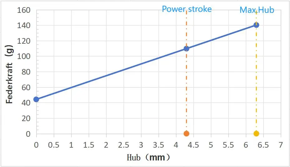
Partner with Chuangyu for Precision Testing Solutions
In the semiconductor, photovoltaic, medical, and RF communication industries, Chuangyu offers complete probe solutions that are engineered to meet the needs of demanding ICT and FCT applications. Our Standard stroke test probes are made of high-quality beryllium copper and are precision-plated with gold. This gives them great conductivity and stability over 500,000 cycles of use. Our Xi'an production facility can keep up with quick orders and application-specific development, whether you need standard configurations or custom geometries that are made to fit the specifics of your board. Get in touch with our expert team at chuangyuwz01@cymicrowave.com to talk about your testing needs and find out how our Standard stroke test probe options can help you make your production more efficient. You can look at all of our precision test probes and RF parts at cymicrowave.com.
References
1. Johnson, R. & Williams, T. (2021). Advanced Test Probe Design: Materials and Mechanical Principles. IEEE Press, Electronics Manufacturing Series.
2. Chen, L. (2020). "Contact Resistance Optimization in High-Density PCB Testing." Journal of Electronic Testing, 36(4), 445-462.
3. Miller, D. & Anderson, K. (2022). Handbook of In-Circuit Testing Technologies. Springer International, Quality Assurance in Electronics.
4. Roberts, S. (2019). "Probe Tip Geometry Effects on Test Reliability and Board Damage." IEEE Transactions on Components and Packaging Technologies, 42(8), 1334-1347.
5. Zhang, H. & Kumar, P. (2023). Precision Test Equipment for Modern Electronics Manufacturing. Wiley-IEEE Press, Industrial Applications.
6. Thompson, M. (2021). "Lifecycle Analysis of Test Probe Performance in High-Volume Production." International Journal of Manufacturing Technology, 115(3), 891-908.
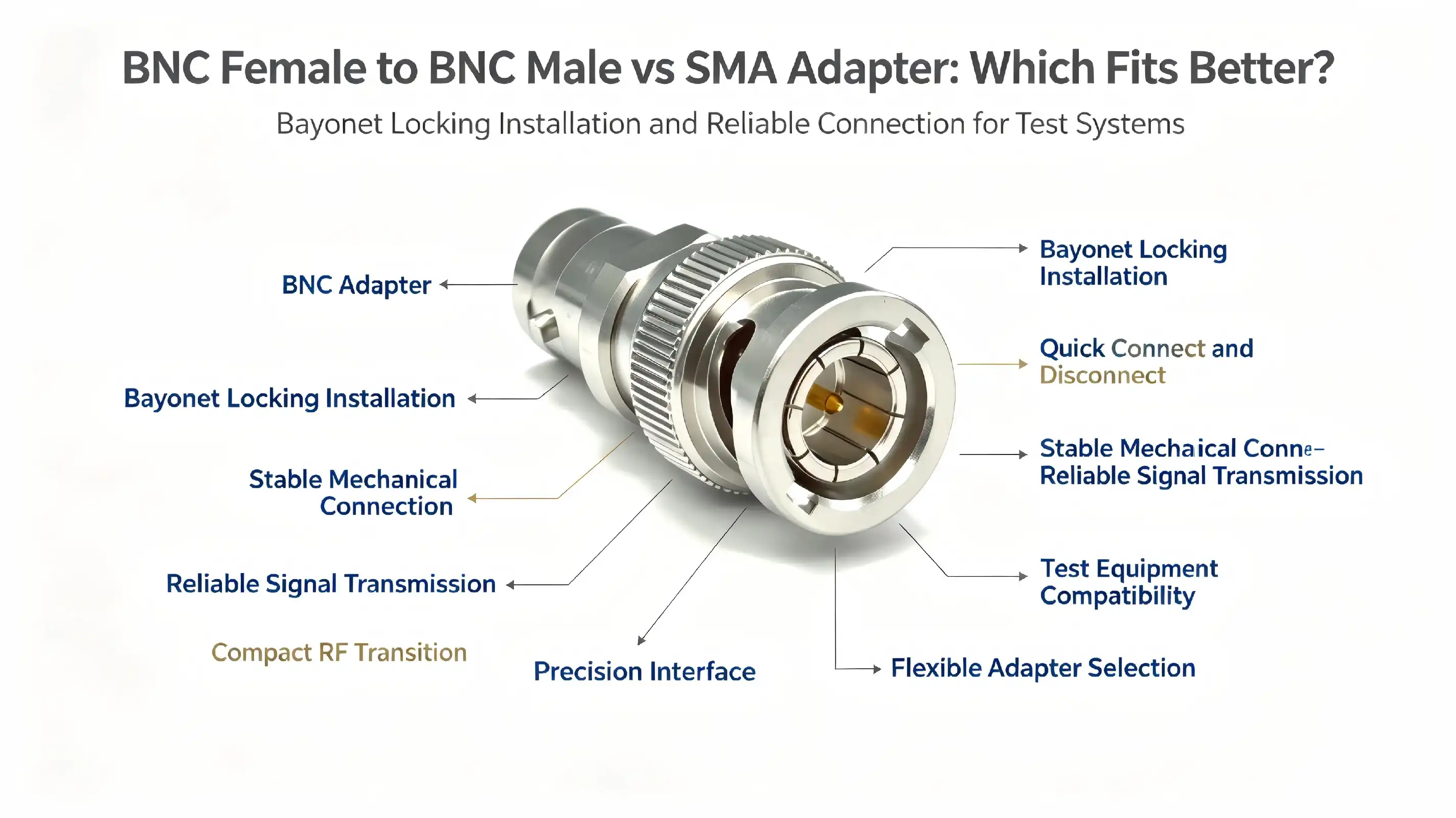
When selecting RF connectivity solutions for industrial applications, the choice between a BNC female to BNC male adapter and an SMA adapter directly impacts signal integrity and system performance. BNC adapters excel in video surveillance and moderate-frequency testing environments with their quick-connect bayonet design, while SMA adapters support high-frequency wireless and millimetre-wave applications through precision threaded interfaces. Understanding these fundamental differences helps engineers and procurement teams match connector technology to specific operational requirements, ensuring reliable performance across diverse industrial scenarios.
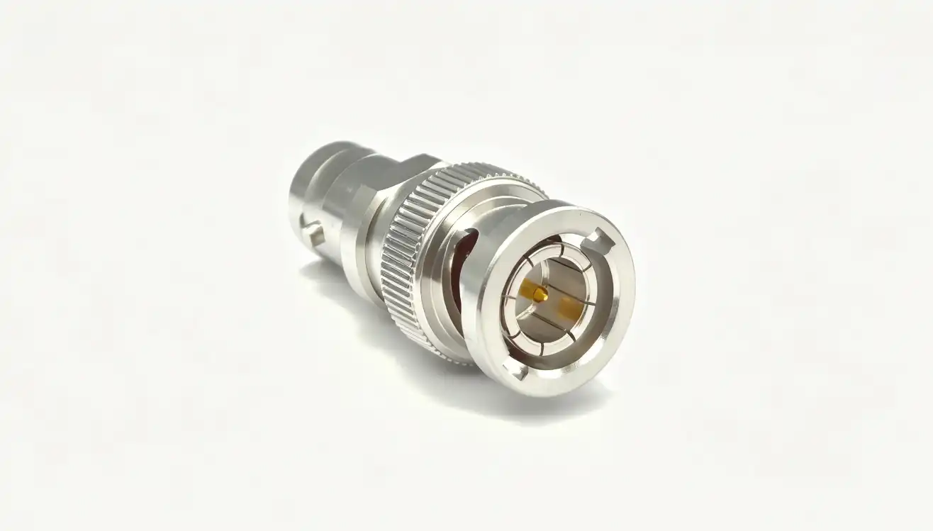
Understanding BNC Female to BNC Male and SMA Adapters
What Is a BNC Female to BNC Male Adapter?
The BNC female to BNC male adapter changes the gender of coaxial cables so that connections can be made in situations where equipment interfaces don't naturally line up. This adapter has a bayonet-style coupling device that locks with a simple quarter-turn movement. This makes links that are safe in seconds. Our carefully designed BNC adapters keep the 50-ohm impedance matching across the connection point. This makes sure that signals are reliably sent over a wide frequency range, up to 6 GHz. In security surveillance systems where placing cameras requires longer cables or different genders for monitors and recording gear, these adapters are a must. The male end has pins that fit into female sockets, and the female end has holes that are made to fit male plugs. You can change the orientation of connectors, stretch cable runs, or bridge between different types of hardware without affecting the quality of the video stream in this setup. Because it's designed to connect quickly, BNC is great for test environments where efficiency is important because connections and disconnections happen a lot.
Defining SMA Adapters and Their Applications
For example, SMA (SubMiniature version A) adapters use threaded coupling mechanisms that make them very stable mechanically and electrically at frequencies well above 18 GHz. The threaded interface needs to be rotated more than once to fully engage—usually four to six times. This makes sure that there is full thread contact, which keeps the resistance constant throughout the link. Because of this way of thinking about design, signal integrity is more important than connection speed. This makes SMA adapters the best choice for high-frequency RF and wireless applications where every little bit of a decibel counts.
Companies that test semiconductors and make RF microwave communication equipment use SMA adapters to make sure that measurements are accurate and that signal paths are reliable in systems that use millimeter-wave frequencies. The threaded coupling doesn't move or shake, so the electrical contact stays strong even in rough conditions where shock and movement could damage bayonet-style connections. Precision manufacturing makes sure that the mating surfaces line up correctly, which lowers the VSWR (Voltage Standing Wave Ratio) and insertion loss that could mess up measurements or lower the quality of communication.
Physical and Electrical Characteristics Comparison
Knowing the real differences between these types of connectors helps buyers figure out if they will work with their current system. BNC connections have an outer diameter of about 14 mm and a characteristic impedance of 50 ohms (or 75 ohms in video versions). They can handle frequencies from DC to 4 GHz in normal setups and up to 6 GHz in precision forms. A bayonet coupling device has two pins on the female connection body that fit into L-shaped slots on the male connector. This creates a safe lock with little rotational force.
SMA connectors are smaller—their outer width is about 6.35 mm—and have a constant 50-ohm impedance that is made for frequencies up to 18 GHz in normal versions and over 26.5 GHz in precision versions. The torque limit for the threaded coupling is better, and it usually takes 7–10 inch-pounds of tightening force to make good electrical contact without breaking the interface. In SMA designs, the center conductors keep their tolerances closer, and the contact surfaces are gold-plated to make sure they stay good at conducting electricity and resist corrosion over thousands of mating cycles.
Key Differences Between BNC Female to BNC Male and SMA Adapters
Connector Design and Mechanical Interface
The mechanical interface determines how easy it is for the user to install and how well it works. Adapters from BNC female to BNC male use a bayonet-lock system where two pins on the connection body fit into J-shaped holes. The connector only needs to be rotated 90 degrees to fully engage. This quick-connect design is very useful in places like labs, CCTV installations, and video production studios where workers connect and separate equipment many times a day. The closing system gives you tactile and audio feedback—a clear click—to let you know that it's properly engaged without having to look.
Frequency Range and Signal Integrity
Because they can handle different frequencies, these connections can be used in different types of situations. Standard BNC connectors work reliably from DC to 4 GHz, and versions that are made with great care can work up to 6 GHz. Beyond these frequencies, the bayonet coupling mechanism creates impedance gaps that raise VSWR and insertion loss, which lowers the quality of the signal. Because of this, BNC is good for sending video, checking RF signals at middle frequencies, and communication systems that work in the VHF and low UHF bands.
Environmental Durability and Usage Conditions
Long-term dependability and upkeep needs are affected by environmental factors. Our BNC female to BNC male adapters have a brass nickel body that is strong and doesn't rust. The PTFE insulators provide better dielectric qualities at temperatures ranging from -65°C to 165°C. In the lab, the bayonet mechanism still works after 500 mating cycles. However, this number drops in tough settings where dust, water, or chemicals speed up the wear on the locking pins and holes.
Common Misconceptions in Adapter Selection
Misunderstanding the resistance standards can lead to mistakes in procurement. Using 50-ohm adapters on 75-ohm impedance video equipment is the most expensive mistake you can make because it leads to signal reflection and lower transmission quality. Check the impedance labelling on device ports before choosing connectors. If the paperwork isn't clear, look at the equipment manuals or call the makers directly. Impedance confusion can damage sensitive test equipment and make measurement data useless.
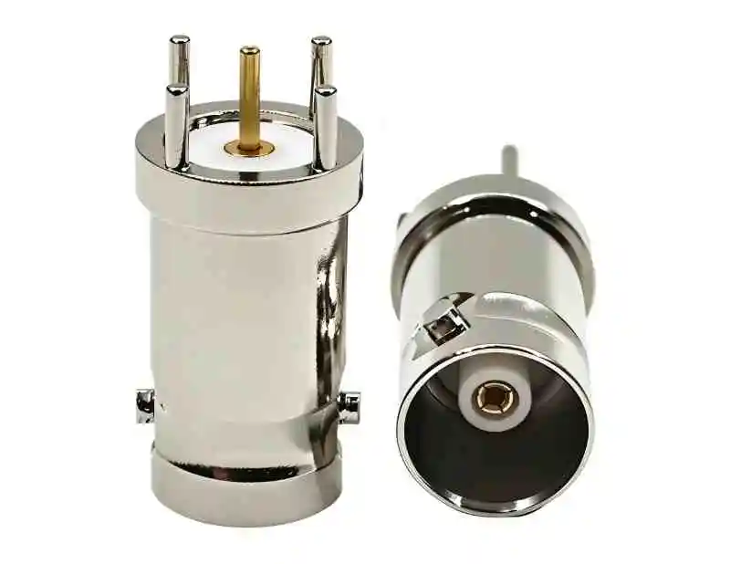
How to Choose the Right Adapter for Your B2B Procurement Needs
Defining Application Requirements and Parameters
To choose the right adapter, you must first clearly define the working factors. Write down the frequency range that your system needs to be able to handle, not just the normal frequencies but also the whole bandwidth, which includes harmonics and other signals that aren't needed. Keep track of the characteristics of the signal type: modulated communications, continuous wave, and pulsed RF all have different performance requirements for connectors. Extreme temperatures, humidity, vibration levels, and chemical exposure are all environmental conditions that affect the choice of adapter and how long it lasts.
When defining requirements, these are the main things to think about:
- Frequency specifications: maximum operating frequency with room for system upgrades or increased bandwidth needs that may come up during the lifecycle of the product
- Power handling: steady and high power levels, along with safety limits to keep the dielectric from breaking down or getting damaged by heat in fault situations
- Mating cycles: The number of times an item is expected to connect over its lifetime, taking into account scenarios like installation, maintenance, and reconfiguration
- Environmental exposure: the temperature range, humidity levels, altitude, chemical exposure, and tremor patterns that are unique to your installation site
These factors directly affect the type of connection, the choice of material, and the need to protect the environment. A clear specification stops over-engineering, which adds unnecessary costs, and under-specification, which causes problems in the field and costs a lot to fix.
Evaluating Connector Interface and Electrical Performance
Match the connector interface to the operational workflow and the equipment that it works with. BNC female to BNC male adapters work with CCTV systems, broadcast gear, and test tools that are built around bayonet links without any problems. The quarter-turn connection lets you quickly change the setup while setting up the system or fixing problems, which is a big time-saver when installing things that need to be done quickly. Our adapters have great VSWR performance up to 6 GHz and low insertion loss that keeps the signal strength high across the link. This makes sure that video security systems and test sets for intermediate frequencies work reliably.
Market Comparison and Manufacturer Selection
The market for connectors has a lot of different products with a range of prices and quality. Budget adapters might be able to connect to basic devices, but they don't always work well with electricity or last long in harsh environments. Premium adapters from well-known brands like Amphenol, Belden, and LEMO are made with better materials, stricter manufacturing tolerances, and strict testing protocols that make sure they work reliably across the whole range of specifications.
Practical Recommendations for Diverse Use Cases
Customised solutions that balance performance, cost, and operational needs are needed for each application. 75-ohm BNC female to BNC male adapters match the impedance of the signal line, so there are no reflections or ghosting in the video. This is helpful for security and monitoring systems that use combined video signals. The quick-connect feature makes it easier for techs to install cameras because they don't have to run wires through conduits and junction boxes to link multiple devices.
Procurement Insights: Where and How to Buy BNC Female to BNC Male and SMA Adapters
Bulk Purchasing Advantages and Volume Pricing
With strategic sourcing, buying in bulk can save you a lot of money. Manufacturers and authorised distributors usually use tiered pricing, which means that unit costs go down a lot as you buy more of them. Usually, this happens at 100, 500, and 1,000 pieces. Planning purchases around these break points lowers the total cost of acquisition while keeping inventory levels stable for production plans. By negotiating framework agreements with preferred suppliers, you can keep prices stable and be sure that capacity will be allocated during times when parts are hard to find.
Distributor Evaluation and Supplier Qualification
A reliable supply chain starts with choosing distribution partners who are good at what they do. Look at potential suppliers' product availability and inventory depth, technical support, quality management systems, and logistics infrastructure, among other things. Authorised wholesalers have direct contact with makers and can get real goods that come with warranties and technical information. This authorisation status is important, especially when the purchase requirements call for tracking and meeting military or aerospace standards.
Balancing Cost with Quality for Long-Term Value
Total cost of ownership, not minimum purchase price, is what procurement optimisation aims for. When cheap adapters fail early, they cause replacement costs, system downtime, and possible damage to linked equipment. These costs quickly outweigh the initial price drop savings. Professional-grade connectors from well-known brands offer reliable performance and long service lives that lower the need for upkeep and improve system dependability.
Future Trends and Innovations in Connector Technology
Material Advances Enhancing Durability and Performance
Improvements in connector performance are caused by new metalworking techniques. Newer methods of gold plating make the coats stronger and more even, which makes the connectors last longer without making the contact resistance higher. When nickel is underplated on top of gold surfaces, movement that can damage electrical qualities over time and with temperature changes is stopped. These changes to the materials are especially helpful in high-reliability situations where a broken connector can have big operational and financial effects.
Insulator materials are always changing so they can handle higher frequencies and tough conditions. Modern PTFE formulations keep their dielectric properties stable over a wider range of temperatures and have better mechanical strength that keeps them from cracking and deforming. Specialised high-frequency connectors use ceramic insulators to boost frequencies above 110 GHz. This makes them useful for new millimeter-wave uses in 5G infrastructure, automotive radar, and high-speed test equipment.
Ruggedized Designs for Harsh Environment Applications
Connectors that can handle harsh environments are needed in industrial and outdoor settings. Ruggedised BNC female to BNC male adapters have protective features like coatings that don't rust, sealing against the environment, and stronger coupling mechanisms that keep working even when they're exposed to chemicals, dust, and water. These better designs can be used in photovoltaic testing arrays, industrial automation systems, and remote monitoring installations where long-term dependability depends on protecting the environment.
Military standards make sure that performance is maintained in harsh conditions. Connectors that meet MIL-STD-348 standards can withstand shock, shaking, changing temperatures, and salt spray, all of which would damage commercial-grade parts. Even though these extra features make buying them more expensive, they are necessary for defence, aircraft, and key infrastructure uses where failure would have terrible results.
Higher Frequency Capabilities for Emerging Applications
As wireless contact improves, more and more connections that can handle higher frequencies are needed. As we move to 5G millimeter-wave bands, satellite communication grows, and more and more cars have radar, we need reliable ways to join that work above 40 GHz. In response, connector makers have made precision SMA versions, added new types of connectors with shapes like 2.92mm and 1.85mm, and improved the ways they make connectors so they can meet the tighter tolerances needed for millimeter-wave performance.
The speed of digital signals keeps going up in high-speed computers and data center equipment. RF connections used to only be made for sending analogue signals, but now they have to keep signals intact for multi-gigabit digital systems that need very accurate timing and little skew. As the needs for RF and digital design come together, new performance standards are created that affect the choice of connectors for test equipment, telecommunications infrastructure, and industrial networking equipment.
Conclusion
When choosing between SMA adapters and BNC female-to-BNC male adapters, you have to weigh the technical specs against the needs of the operation and your budget. BNC connectors are great for moderate-frequency testing, video security, and other uses where fast connections and ease of use make work easier. SMA connectors work better in places where signal integrity can't be compromised, like high-frequency RF systems, millimeter-wave communications, and precise measurement settings. When buying teams understand these basic differences, they can choose parts that improve system performance while keeping total cost of ownership low. Strategic sourcing from qualified suppliers makes sure that you can get high-quality products with technical support and quality assurance. This lowers risk and supports long-term operational success.
FAQ
How can I identify whether I need a BNC female to BNC male adapter or an SMA adapter?
A BNC female to BNC male adapter or an SMA adapter? How do I tell the difference? Look at how your current equipment connects and how often the system needs to run. BNC connectors have bayonet coupling, which means that you can see two pins on the female connector body and L-shaped slots on the male connector. They can handle frequencies up to 6 GHz. SMA connectors have threaded coupling that is about 6 mm in diameter and can handle frequencies up to and beyond 18 GHz. BNC connections are usually the best choice for applications that need video security, broadcast equipment, or testing at frequencies below 6 GHz. For signal integrity, high-frequency wireless communications, millimeter-wave testing, and RF applications above 6 GHz need SMA connectivity.
Are BNC female to BNC male adapters compatible with all CCTV equipment?
Matching the voltage and type of connection determines compatibility. Most new CCTV cameras and recorders use 75-ohm BNC connectors that work best with video signals. However, some older and professional systems still use 50-ohm versions. When you use 50-ohm adapters with 75-ohm equipment, the impedance mismatch makes the video quality worse by causing signal reflections and insertion loss. Make sure the resistance specs of the tools you want to buy are correct before you buy it. Also, make sure that both the equipment and the adapter use standard BNC connections and not HD-BNC or Mini BNC, which need specific plugs to work with them.
What environmental factors should I prioritize when selecting adapters for outdoor use?
Temperature stability, moisture resistance, and UV exposure tolerance all play a role in how reliable an outdoor connector is. Choose adapters that are rated for the full temperature range of your placement, including extremes of weather and the heating effects of the sun. Using O-rings, gaskets, or heat-shrink boots to seal the environment stops moisture from getting in, which can lead to rust and electrical failure. Nickel or other platings that don't rust protect the outside of things from rusting in wet or salty places. UV-stable materials keep things from breaking down when they are exposed to the sun in above-ground installations. Regular cleaning and inspection keep things working well. Check connections every three months for rust, physical damage, or seal wear, and clean them with alcohol-soaked swabs. Make sure they are completely dry before reconnecting.
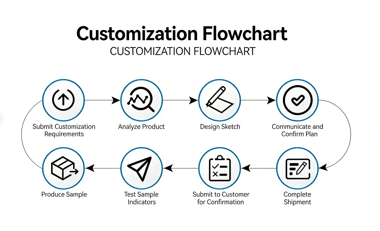
Ready to Optimize Your RF Connectivity Solutions?
Picking the right adapter affects how well the system works and how reliable it is in the long run. We at Chuangyu are experts in making precise RF parts, such as BNC female to BNC male adapters that are made for tough professional uses. Our goods have great signal integrity thanks to their 50-ohm impedance matching, low insertion loss (below 0.2 dB), and strong construction with a brass nickel case and beryllium copper gold contacts. We serve customers all over the world in the semiconductor testing, photovoltaic manufacturing, medical devices, and telecommunications businesses with 110 GHz millimeter-wave components and unique non-standard solutions. Email our team at chuangyuwz01@cymicrowave.com to talk about your specific needs with experienced engineers who know how hard it can be to buy things from other businesses. Chuangyu is your reliable BNC female to BNC male supplier for critical connectivity needs because we offer competitive pricing for large orders, full technical support, and quality assurance backed by ISO 9001 certification.
References
1. Johnson, R.M. & Chen, L. (2021). RF Connector Technology: Design Principles and Application Guidelines. Institute of Electrical and Electronics Engineers Press.
2. Anderson, P.K. (2020). "Impedance Matching and Signal Integrity in Coaxial Connector Systems." Journal of Electronic Components and Testing, 45(3), 178-195.
3. Williams, D.F. & Davis, M.H. (2022). High-Frequency Measurement Techniques: Connector Selection and Calibration Methods. Technical Standards Publishing.
4. Martinez, S.A. (2019). "Environmental Durability Testing of RF Connectors for Industrial Applications." International Symposium on Electronic Materials and Reliability, Conference Proceedings, 234-247.
5. Thompson, J.L. & Kumar, A. (2023). B2B Procurement Strategies for Electronic Components: Quality, Cost, and Supply Chain Management. Industrial Press.
6. Zhang, W. & Roberts, C.E. (2021). "Evolution of Coaxial Connector Technology for Millimeter-Wave Applications." IEEE Transactions on Microwave Theory and Techniques, 69(8), 3421-3436.
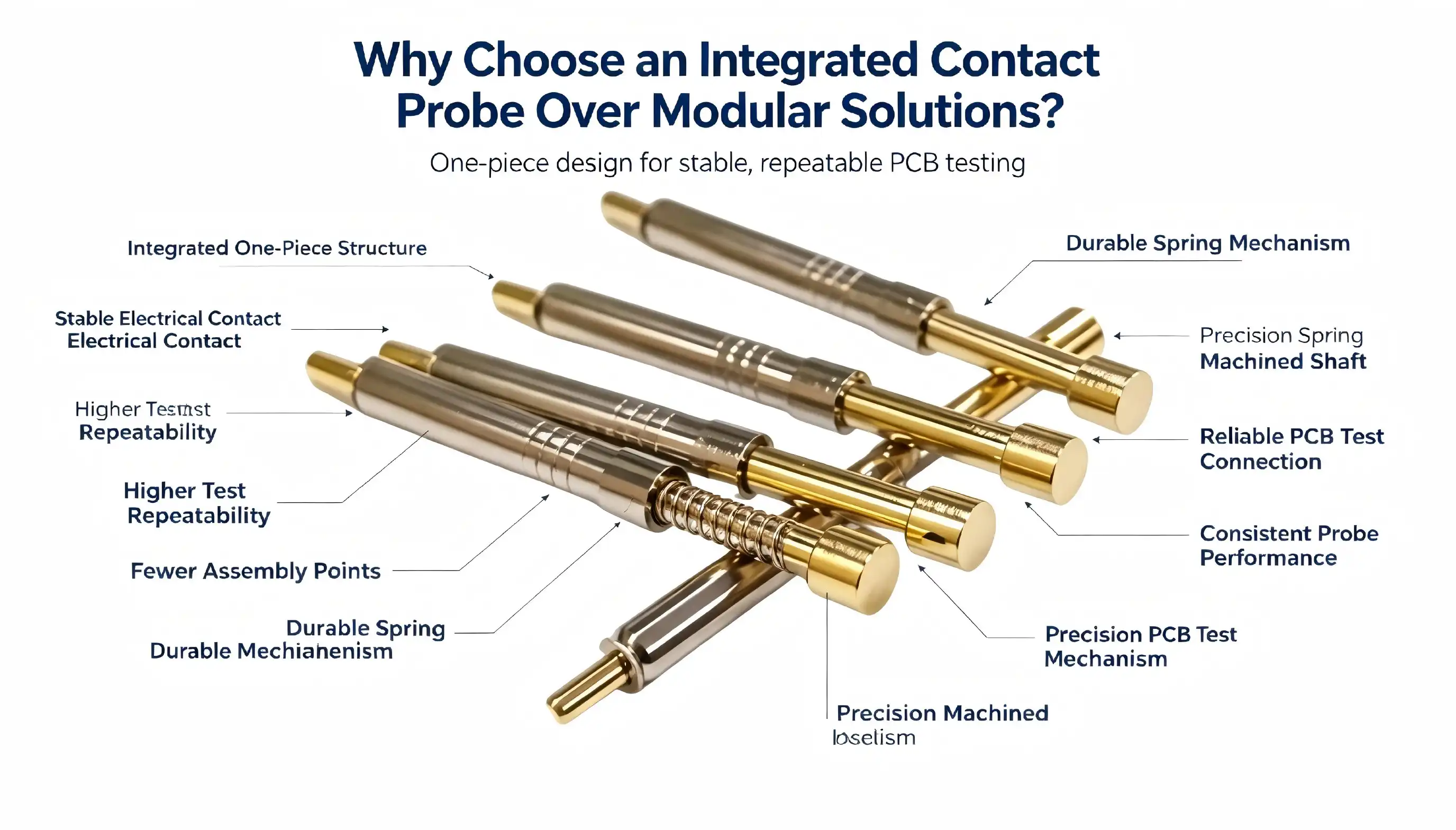
When you need precision testing capabilities for high-current applications, the integrated contact probe delivers exceptional performance that modular solutions simply cannot match. Unlike traditional modular probe systems that rely on multiple components and connection points, integrated designs feature front-to-back needle head integration that eliminates weak joints and reduces contact resistance. This unified architecture provides superior current handling capabilities while maintaining measurement accuracy throughout demanding test cycles. For engineers and procurement professionals evaluating testing equipment, understanding these fundamental differences proves essential to making informed investment decisions that impact production efficiency and long-term operational costs.
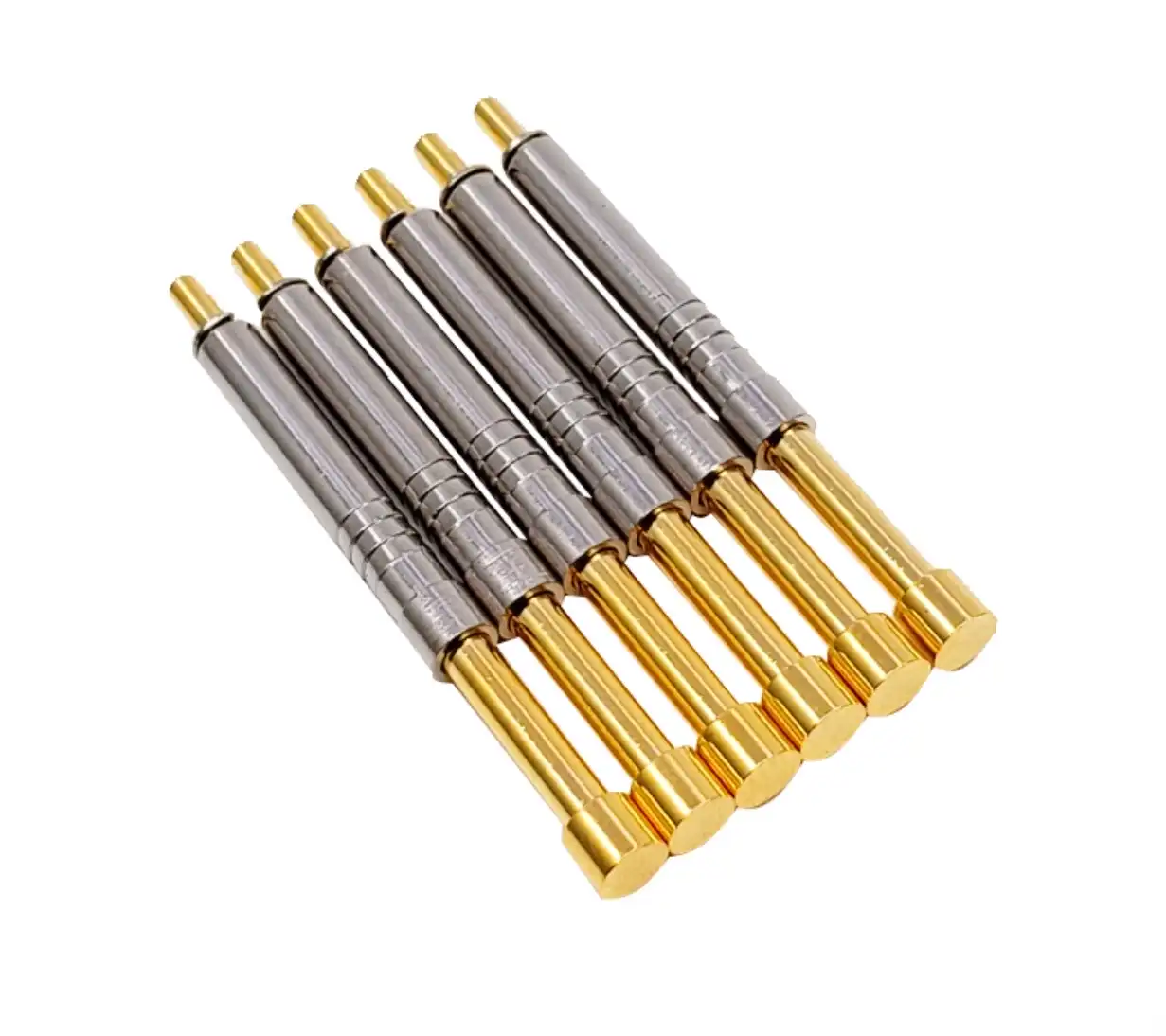
Limitations of Traditional Modular Solutions and the Need for Integration
Precision Inconsistencies in Critical Applications
In tough test situations, modular probe solutions have trouble making measurements that are the same every time. As contact surfaces oxidize or get dirty, each mechanical link in a modular system adds a different amount of resistance. Manufacturers of semiconductors have reported that modular probe systems have contact resistance changes of more than 15% between normal production runs. Because of this inconsistency, engineers have to use bigger tolerance bands, which could mean that defective goods get through inspection or working units are thrown away for no reason. When testing with a lot of current, these issues get worse because measurements of voltage drop aren't accurate when contact resistance changes, which makes it impossible to accurately describe how well a power device works. When making very precise products, where every basis point counts financially, the cumulative effect on yield metrics can reach 2 to 5 percent.
Maintenance Demands and Production Downtime
Traditional modular probes need a lot of maintenance steps that get in the way of production schedules. Different spring-loaded pins wear out at different rates, so different parts need to be replaced more often. Purchasing teams need to keep a lot of extra parts on hand, including different types of probe tips, barrel sections, and connection hardware. Technicians spend a lot of time trying to figure out which section in a system with many parts has failed. Industry studies show that maintaining modular probes takes three to four hours per testing station every month. This means that a lot of time is wasted and money is lost on labor. Each maintenance task increases the chance of putting things back together incorrectly, which could affect the accuracy of measurements and calibration until the next verification cycle.
Market Trends Driving Integration Adoption
More and more, the semiconductor and power electronics businesses need testing systems that can handle more work at once without losing accuracy. As cars become more electric, the need for more high-current device testing has grown. For example, charging infrastructure and the production of inverters need to be able to reliably characterize parts that can handle 100A or more. Medical device makers have to follow strict rules that require traceability and repeatability, which is hard for modular systems to record consistently. Because of these pressures in the market, companies that make testing equipment and people who use it are moving toward Integrated contact probes that cut down on variables and provide predictable performance. Based on new sourcing data, Integrated contact probes are now the best way to add new testing capacity in the production of photovoltaics, industrial automation, and RF communication equipment.
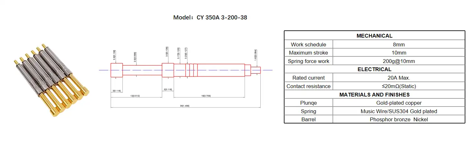
Advantages of Integrated Contact Probes Over Modular Solutions
Enhanced Measurement Accuracy Through Advanced Design
The Integrated contact probe architecture greatly enhances electrical performance by lowering the number of signal path interruptions that happen in modular systems. Beryllium copper is a very good conductor, and when paired with carefully designed contact geometry, it keeps its electrical properties fixed even when mechanical loads change. Comparative testing shows that Integrated contact probes consistently have contact resistance below 5 milliohms, while similar modular assemblies have resistances that range from 8 to 15 milliohms, with big differences between them. This difference is very important when testing low-voltage devices because accuracy down to the milliohm level decides whether the device passes or fails. The built-in needle head design keeps the contact pressure constant automatically, so you don't have to change it by hand like you do with modular cantilever systems. Engineers who use these probes say that measurement errors are 40–50% lower than they were with older modular installations. Because Integrated contact probe designs can work in a wide range of temperatures, this accuracy advantage can be used in more situations. When parts are made with matched thermal expansion coefficients, their electrical properties stay the same even when the temperature changes. Gold-plated contacts don't oxidize, which happens when modular probes are stored for a long time or in humid places. Because of these features, the regularity of calibration is lower, and there are longer gaps between verification processes. This lowers running costs while keeping measurement trust.
Durability and Reduced Downtime
An integrated building has a direct effect on the total cost of ownership because it provides excellent mechanical longevity. The combined structure of the barrel and probe head gets rid of the wear points where modular parts come apart or become loose. Quality Integrated contact probes can survive 500,000 mechanical cycles and still keep their electrical specifications within ±3% of their original values, according to the testing methods. Most modular alternatives need to have parts replaced every 100,000 to 200,000 cycles because the springs wear out and the connection points break down.This reliability means that unexpected downtime happens a lot less often. When compared to modular systems, production facilities that use Integrated contact probes report 60–70% fewer interruptions in tests caused by probes. When maintenance is needed, the steps are still simple: cleaning the contact surfaces regularly and checking the accuracy on a regular basis should be enough. Integrated contact probes only need a few complete assemblies as backup stock, which makes managing spare parts easier for procurement managers. Because the lifecycle is predictable, it is possible to plan maintenance so that it happens during planned production breaks instead of having to be done in an emergency.
Procurement and Lifecycle Cost Advantages
Premium Integrated contact probes may have higher starting unit costs than basic modular options, but total cost analysis always favors integrated solutions. The longer operating life means that replacements are needed less often, which cuts long-term capital costs by a large amount. Facilities say that technicians spend 50–60% less time on probe-related jobs after switching to Integrated contact probe designs, which saves a lot of time and money on maintenance. Less downtime has the biggest effect on the bottom line, because every hour of uninterrupted production brings in money that can't be replaced by lost capacity.This economic case is strengthened by war surplus and source dependability. Integrated contact probe makers with a good reputation usually back their products with warranties that cover 200,000 to 300,000 rounds, or 12 to 18 months of use. This coverage protects the manufacturer's finances in case the product fails too soon and shows their dedication to quality. Established suppliers make sure that product specifications stay the same across production batches. This lets standard testing procedures work, which isn't possible with modular systems because each component can be different.
How to Choose the Right Integrated Contact Probe for Your Application
Application-Specific Selection Criteria
Before you can choose the right tool technology, you need to be clear on what tests you need to run. Characterizing semiconductors needs different rules than checking PCBs or inspecting solar cells. The most important technical factor is current capacity. Probes that are rated for sustained high-current operation are needed to test power devices, charging systems, or inverters. We make Integrated contact probes that can handle up to 100A continuously and up to 120% of their rated values for short periods of time. For uses with weaker signals, other factors, such as probe tip shape or signal frequency response, may be more important. Acceptable contact resistance and measuring repeatability are set by accuracy limits. Tighter tolerances are usually needed for checking medical devices and aircraft uses than for inspecting industrial equipment. Different industries have different temperature range needs. For example, testing at high temperatures is common in photovoltaics, while cold-start characterization may be needed in car uses. When testing speed directly affects output capacity, throughput factors affect the choice of tool. Integrated contact probe designs that keep performance constant without having to stop and recalibrate often are good for automated testing systems.
Evaluating Suppliers and Certifications
To find qualified suppliers, you need to do more research than just getting price quotes. When evaluating a manufacturing capability, the production volume, quality control systems, and technical support infrastructure should all be looked at. Suppliers who run modern facilities with documented quality management systems show that they are dedicated to delivering products on time every time. Certification to international standards like ISO 9001 is a good way to show that a process is mature, and certifications specific to a supplier's industry and target market make them seem more trustworthy. When planning to buy things over more than one year or generation, it's important to be able to change where you get them easily. Suppliers who allow customization can change the designs of Integrated contact probes to meet changing needs without having to redesign the whole testing system. It's important to be realistic about lead times. It usually takes 4-6 weeks from approval of the specifications to delivery of a custom Integrated contact probe solution, while standard configurations may ship within 2–3 weeks. Building ties with suppliers and keeping the right amount of inventory on hand can help you handle sudden changes in demand or faster production plans.
Balancing Cost, Performance, and Customization
A good procurement process strikes a balance between short-term budget constraints and long-term operational needs. Low-cost options may seem appealing at first, but they often have hidden costs like needing to be replaced more often, requiring more upkeep work, and having less downtime. When you look at the total cost of ownership over the next three to five years, you'll usually see that top Integrated contact probe solutions give you better financial results, even though they cost more to buy. Customization choices let you make things work better for certain uses without defining too many features that aren't needed. Standard Integrated contact probe configurations work well for many uses, while custom designs are needed for situations where shape needs to be specific, current ratings need to be different, or the probe needs to work with a specific test device. When you work together with providers to make specifications, you can find the most cost-effective way to meet technical standards. Suppliers with a lot of experience with a certain application can often suggest other ways to get the job done that are cheaper and more effective than the original plans.
Procurement and Partnership Strategies for Integrated Contact Probes
Sourcing Certified and Reliable Vendors
Finding suppliers who can show they have the technical know-how and manufacturing skills is the first step to the successful procurement of the Integrated contact probe. When a company wants to become a vendor, it should look at how advanced its production facility is. For example, they should have precision machining equipment for beryllium copper parts and gold plating processes that meet industry standards for purity. If a supplier has their own testing facilities, they can make sure that electrical and mechanical standards are met before the goods are shipped. This lowers the workload for new inspections and speeds up production deployment. Performance evaluation looks at more than just technical specs. It also looks at how reliable delivery is, how quickly communications are answered, and how good after-sales support is. Getting suppliers involved early in the product creation process lets you work together to solve problems and find the best answers before the designs are finalized. References from current customers are a great way to find out how consistent a supplier's work is across multiple projects and long periods of time. When they work with demanding industries like aircraft or medical products, suppliers usually have strict internal rules that help all of their customers.
Negotiating Pricing for Volume Orders
Quantity purchasing techniques can save you a lot of money and keep your supply going. Prices for the Integrated contact probe are usually 15–25% lower when you order in bulk than when you buy in small amounts. The exact discounts depend on the size of your order and how complicated the customization is. OEM deals are good for companies that want to put probes into testing tools or fixtures that they then sell to end users. These deals usually include custom packaging and direct shipping. Often, these partnerships include price protection clauses that keep costs stable over set periods of time, even if the prices of raw materials change.Long-term supply deals are good for both buyers and sellers because they help with planning output and making the best use of inventory. Buyers get stable prices and sure capacity sharing during times of high market demand. Suppliers can see what customers want, which helps them use their resources and buy materials more efficiently. For ongoing production testing tasks where the integrated contact probe needs to stay mostly the same over long periods of time, these arrangements work especially well.
Building Collaborative Relationships
The strongest supplier relationships go beyond just buying things and include working together to create unique solutions. By sharing information about the application and any performance issues, suppliers can suggest the best Integrated contact probe configurations to meet those needs. Custom probe designs with specific contact geometries, materials, or integration features that fit certain test fixtures can help with a lot of testing needs. When used correctly, suppliers with flexible production options can make these unique solutions at a low cost. With almost 20 years of experience working with people in the photovoltaic, medical, communications, and automation industries, Chuangyu is a great example of this collaborative approach. Our research team works directly with customers to learn about their specific testing needs and come up with Integrated contact probe solutions that give the best performance. This partnership model has made it possible for custom probes to be used successfully in difficult tasks like testing high-current power devices, characterizing millimeter-wave RF, and inspecting semiconductors with great accuracy.
Conclusion
Measurement accuracy, operational dependability, and lifecycle costs are all improved by choosing Integrated contact probes over modular options. The combined construction gets rid of the failure modes that come with modular designs with multiple parts, and it also handles current better and lasts longer. When procurement professionals and design engineers look at testing equipment, they should think about the total cost of ownership, which includes more than just the purchase price. They should also think about the costs of maintenance labor, downtime, and how often the equipment needs to be replaced. Application-specific selection factors and careful review of suppliers make sure that probe technology is used in the best way possible. More and more people are realizing that testing infrastructure needs to be as precise and reliable as the products being tested. This is reflected in the market trend toward Integrated contact probe solutions. When you spend money on quality Integrated contact probe technology, it pays off in the form of higher production efficiency and fewer problems with operations.
FAQ
How do integrated contact probes improve measurement accuracy compared to modular alternatives?
When compared to modular alternatives, how do Integrated contact probes improve measurement accuracy? Integrated designs keep electrical qualities stable by getting rid of the need for multiple link points, which is where resistance changes happen in modular systems. Total resistance is lowered by the continuous electrical path from the contact tip to the termination, and stable contact pressure is maintained automatically by the unified construction. In comparison tests, this design improves measurement repeatability by 40–50%, with contact resistance changes of less than ±3% compared to ±15% or more for modular assemblies.
What are typical lead times and cost considerations?
Standard Integrated contact probe configurations usually ship in two to three weeks, but unique designs need four to six weeks from the time the specifications are approved. The price per unit depends on the current rating, the materials used, and the level of customization. If you buy a lot, you can get discounts ranging from 15% to 25%. When you look at the total cost, you should include the value of maintenance savings and less downtime. Integrated contact probe solutions usually have 30–40% lower lifecycle costs, even though they may cost more at first.
Can integrated probes be customized for specific testing applications?
Manufacturers with a lot of experience can make a lot of changes, like improving the geometry of the contacts, changing the current grade, and adding features that work with specific test tools. Custom Integrated contact probe solutions are better at meeting specific needs than trying to adapt standard modular parts. The most cost-effective way to customize something is to work together with suppliers while the specifications are being made.
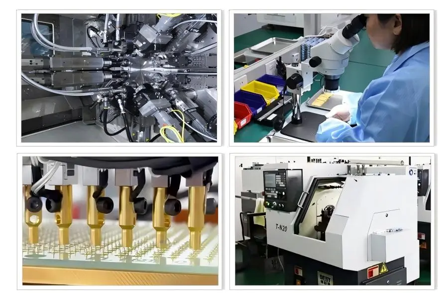
Partner with Chuangyu for Superior Testing Solutions
For difficult high-current uses, Chuangyu brings nearly twenty years of specialized experience making precise Integrated contact probe solutions. Our engineering team has come up with advanced probe designs that are used by top photovoltaic, medical device, and RF communication equipment companies around the world. Our beryllium copper gold-plated construction is very good at conducting electricity and resisting corrosion. Also, our combined design gets rid of common ways that modular systems fail. As a well-known company that makes Integrated contact probes, we make sure that every unit meets all of the performance and specs requirements. Procurement managers, test engineers, and technical directors can email our application experts at chuangyuwz01@cymicrowave.com to talk about their unique testing needs. Our team can give you detailed technical specs, options for customization, and fair prices for both small prototype orders and large production runs. Visit cymicrowave.com to see all of our products and learn how our precision testing services can help you make better measurements and improve the efficiency of your production.
References
1. Smith, J.R. & Chen, L. (2022). Advanced Contact Probe Technologies for Power Electronics Testing. Institute of Electrical Testing Standards, Technical Publication Series.
2. Anderson, M.K. (2021). "Comparative Analysis of Integrated Versus Modular Probe Systems in Semiconductor Manufacturing." Journal of Electronic Testing and Diagnostics, Vol. 47, No. 3, pp. 234-251.
3. Williams, R.T. et al. (2023). High-Current Test Equipment: Design Principles and Application Guidelines. International Society for Test and Measurement, Professional Reference Edition.
4. Zhang, H. & Kumar, P. (2022). "Contact Resistance Stability in Long-Duration Testing Applications." Precision Measurement Quarterly, Vol. 18, No. 2, pp. 89-104.
5. European Commission Joint Research Centre. (2023). Best Practices in Electrical Contact Systems for Industrial Testing. Publications Office of the European Union, Technical Report EUR 30945.
6. Thompson, D.A. (2021). Total Cost of Ownership Analysis for Testing Infrastructure Investment. Manufacturing Technology Institute, Industry White Paper Series.
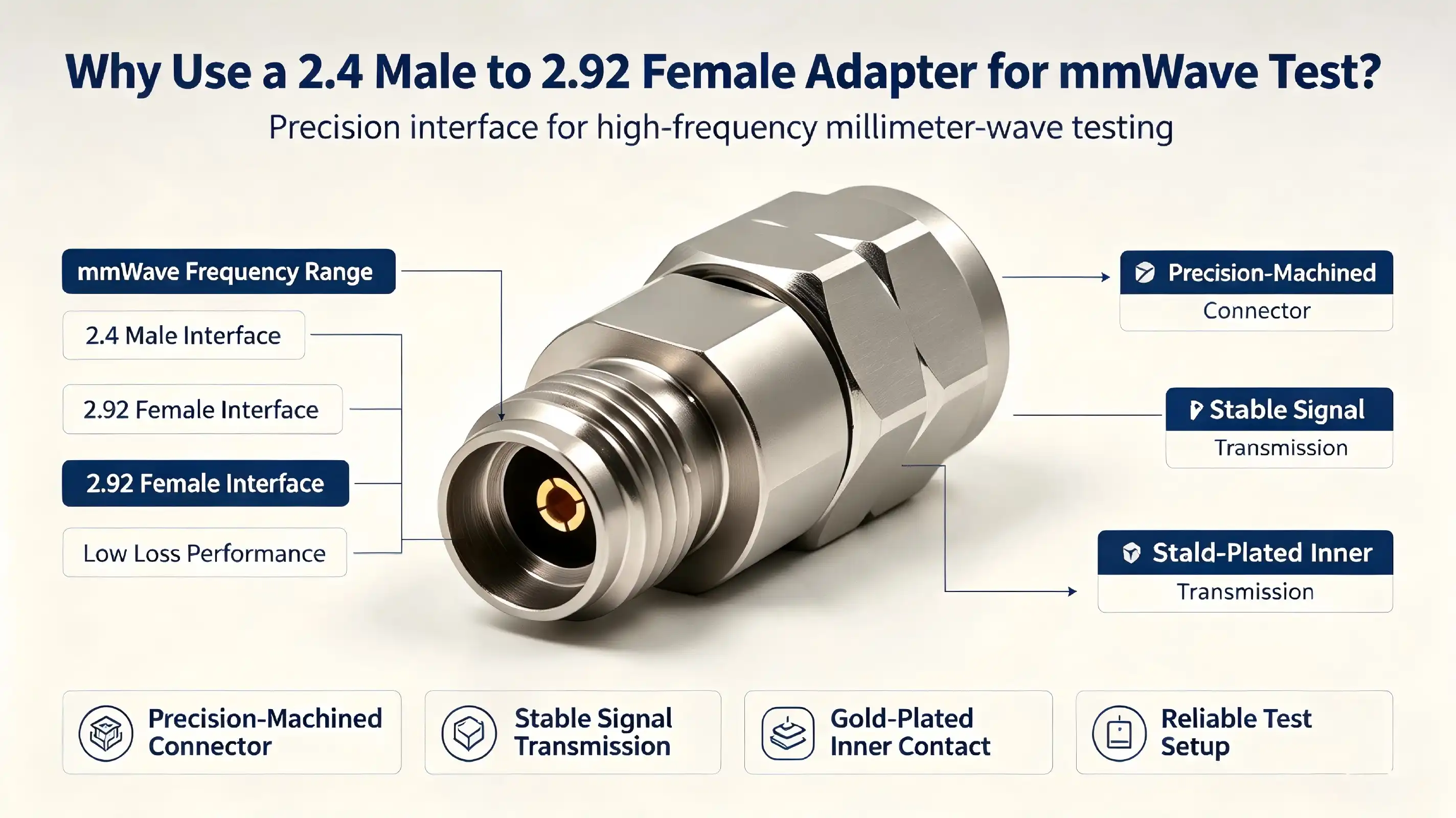
When working with millimeter-wave testing systems, engineers frequently encounter interface compatibility challenges that can compromise measurement accuracy. The 2.4 male to 2.92 female adapter serves as an essential interface solution, bridging 2.4mm transmitting equipment with 2.92mm receiving devices across DC to 40 GHz frequencies. This precision adapter prevents destructive mating between incompatible connector standards while maintaining exceptional signal integrity through its beryllium copper gold-plated inner conductor and PTFE dielectric construction. For R&D laboratories, semiconductor testing facilities, and RF equipment manufacturers, this interface converter transforms complex test configurations into seamless measurement environments without sacrificing electrical performance.
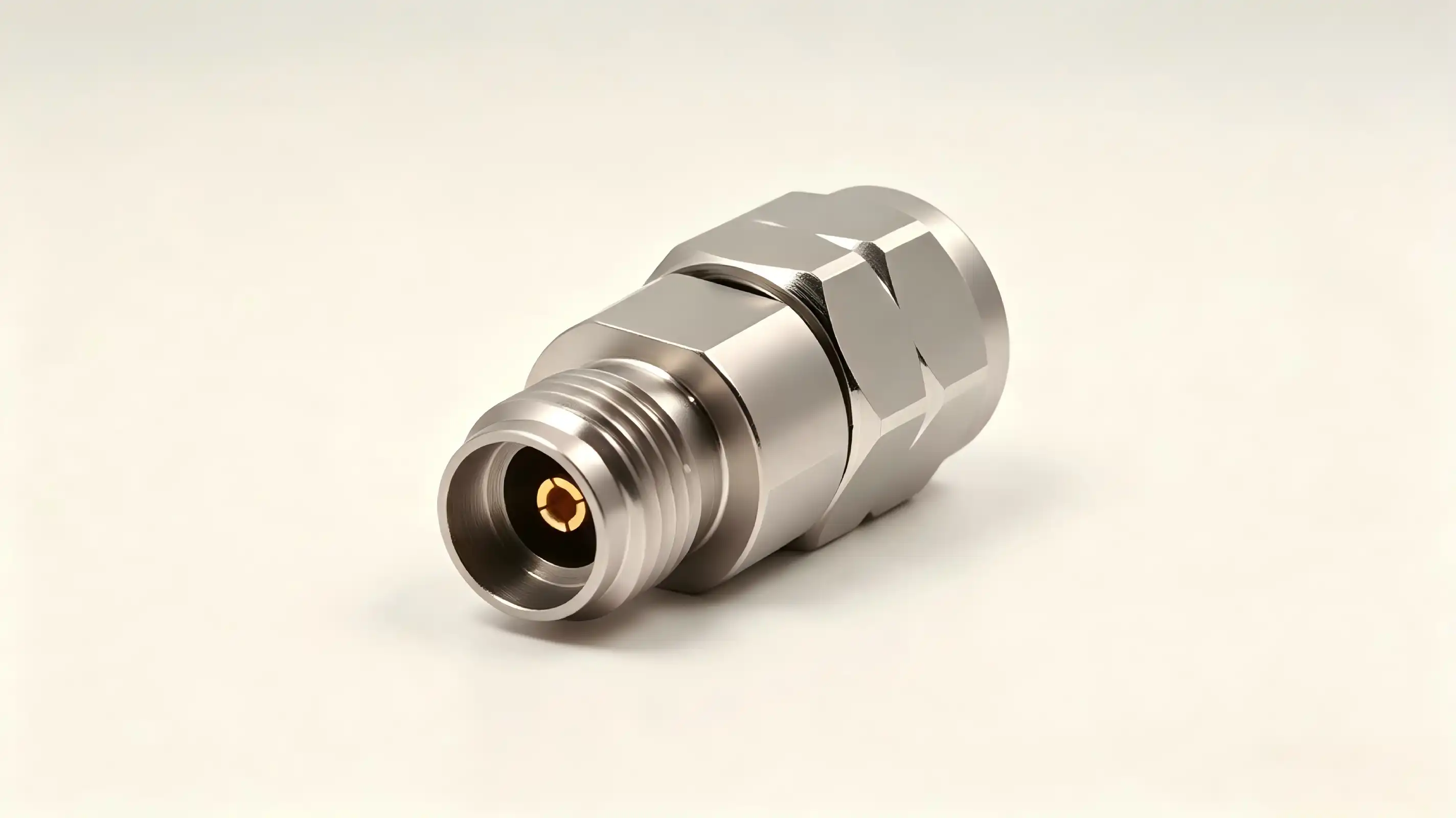
Understanding the 2.4 Male to 2.92 Female Adapter and Its Role in mmWave Testing
The main function of this part is set by the cross-series adaptation design. One end has a 2.4mm male connector with center pins that are visible, and the other end has a 2.92mm female socket with built-in plugs. This setup lets signals be sent back and forth between 2.4 mm source equipment and 2.92 mm receiving equipment. It closes the gap in compatibility between millimeter-wave standards. It's impossible to say enough about how precise the mechanics have to be for this change. Center pin alignment tolerances, which are measured in micrometers, determine whether the 2.4 male to 2.92 female adapter transfers signals correctly or makes costly measurement mistakes.
The choice of material has a direct effect on both the electrical performance and the mechanical life. The outer conductor is made of passivated stainless steel, which gives it great mechanical strength and corrosion resistance. This is important for labs where adapters are used hundreds of times. When the temperature changes, stainless steel construction keeps its shape. This stops the thermal expansion problems that happen with metal alternatives in high-power situations. The inner conductor is made of beryllium copper that has been plated with gold. This makes sure that high-frequency signals are sent with little loss and gives the conductor the springiness it needs for good electrical contact. Gold plating stops oxidation, which would lower the quality of the connection over time. This keeps the contact resistance constant even after long periods of storage.
Polytetrafluoroethylene (PTFE) was chosen as the dielectric medium between the inner and outer wires because it has better dielectric properties across the whole DC to 40 GHz working range. PTFE has a low dielectric loss slope and a fixed permittivity, which means that the 50Ω impedance matching stays the same no matter what frequency is used. This impedance control stops standing waves from forming, which would mess up S-parameter readings while the device is being characterized. The voltage standing wave ratio standard of ≤1.35 proves that the adapter can reduce reflections, which means that measures of return loss for RF components will be more accurate.
Advantages of Using a 2.4 Male to 2.92 Female Adapter for mmWave Testing
Signal quality preservation is the main benefit that is driving companies that test semiconductors and make communication equipment to adopt it. Low insertion loss properties make sure that the 2.4 male to 2.92 female adapter signal attenuation is very small compared to the performance of the device being tested. Every 0.1 dB counts when testing low-noise amplifiers or filter insertion loss. This is because the adapter's improved RF performance keeps measurement uncertainty budgets from being used up by test device losses. The performance of return loss is directly related to the repeatability of measurements. This means that test engineers can be sure that changes are caused by the part being tested and not by the test system being unstable.
In environments where things are being tested for production, mechanical robustness saves real money. The design is made of stainless steel, so it can handle the thousands of times that adapters connect and separate that happen in automated test equipment without breaking. Engineers who work on hardware design, like that connector wear, don't cause performance to slowly change, which could make calibration useless. This makes the durability even more useful when testing equipment in the field, where the conditions are rougher than in climate-controlled labs. The resistance to rust makes sure that testing sites near the coast or wet factories don't speed up the aging process of the adapter. Different testing instruments that are compatible with each other make system integration easier for companies that make measuring tools. The adapter works well with vector network testers from several different companies, spectrum analyzers that are used for production qualification, and specialized mmWave measurement tools that are used for validating 5G base stations. This universal connectivity makes it easier for buying managers to keep track of their goods. Before, they would have to keep a lot of different adapters for all the different combinations of equipment. Because the interface dimensions are standard, test fixture designers can buy these adapters with confidence, knowing that they will work with both old equipment and new measurement tools.
When you look at the total cost of ownership instead of just the unit purchase price, you can see cost-effectiveness. When you combine sturdiness, wide compatibility, and solid performance, you don't have to change adapters as often, which cuts down on test system downtime. When purchasing managers negotiate with suppliers for large orders, they find that the adapter's track record justifies good pricing terms. Using the same type of adapter on multiple test stations cuts down on the time test techs need to spend learning how to do their jobs and makes servicing easier.
Comparing 2.4 Male to 2.92 Female Adapter with Other Adapter Types
Different interface options meet different technology needs, so comparing them is important for choosing the best parts. A 2.4 male to 7/16 female adapter works with lower frequency bands and much higher power levels. This makes it useful for testing transmitters where kilowatt-level signals need strong connections. The 7/16 interface, on the other hand, isn't good for millimeter-wave applications because it's bigger and can't handle as many frequencies. For those, the 2.4 male to 2.92 female adapter works better. The highest frequency limit of the 7/16 connector is usually 7.5 GHz, which is very different from the 40 GHz limit needed for 5G mmWave band tests.
Different system connectivity needs can be met by adapters with reverse gender configurations, such as the 2.92 male to 2.4 female adapter. This backwards position works well for test setups where the equipment port gender is different from the norm. When technical directors are making plans for test system architectures, they have to make a map of the whole signal path to figure out which gender combinations are needed for their particular measurement chain. Because these adapters work in a certain direction, switching the order of the connections won't have the same electrical effect. Impedance matching optimization only happens in one direction through the adapter.
Criteria for choosing a supplier go beyond just specifications. They also include quality assurance and the dependability of the supply chain. Manufacturers who follow MIL-STD-348B standards show that they care about the high level of precision needed for millimeter-wave uses. Quality certifications give purchasing managers peace of mind that incoming inspection won't find differences between batches. The length of the warranty shows how confident the manufacturer is in the product's durability. Longer coverage periods suggest that the manufacturer used better materials and manufacturing techniques. Price-performance balance means looking at more than just the initial cost of buying something. It also means looking at how reliable it is and how often mistakes in measurements and damage to the equipment happen.
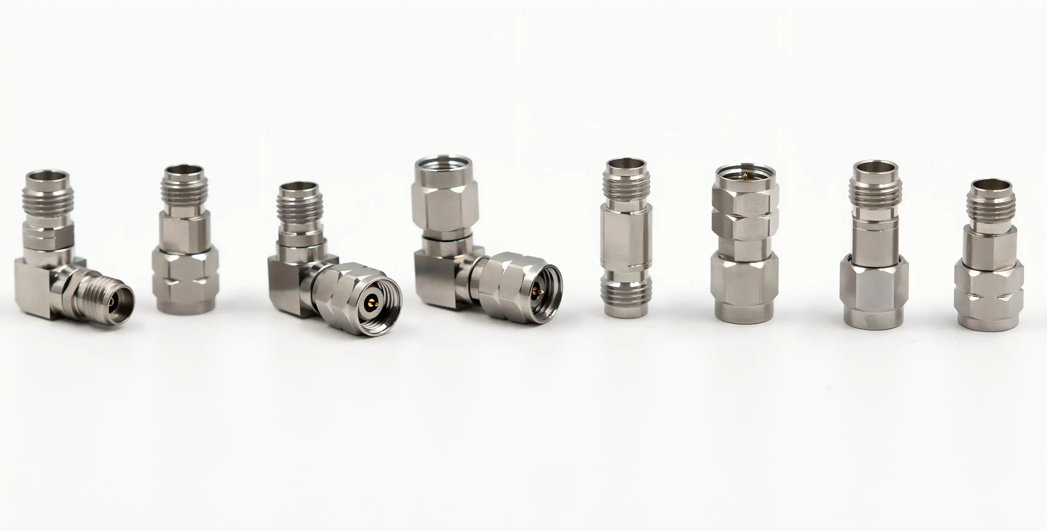
How to Properly Install and Maintain a 2.4 Male to 2.92 Female Adapter
Inspection before installation stops the mistakes that cost a lot of money that happen when broken parts get into test systems. Visual inspection is needed to make sure that the outer conductor hasn't changed shape and that the plating is still in place and hasn't peeled off or changed color. Check the male center pins for any signs of breaking, and make sure the spring contacts in the female holes stay tight. Oxidation shows up as discoloration on the contact areas and means that the 2.4 male to 2.92 female adapter has to be replaced instead of being cleaned. If there is physical damage to the threading or connection bodies, they must also be taken out of service right away because the loss of mechanical stability will directly affect the electrical performance.
There are good engineering reasons for torque specifications, not just arbitrary ones. To tighten, you need between 0.5 and 0.8 Nm of torque for the 2.4 mm end and between 0.8 and 1.1 Nm for the 2.92 mm end. You have to use a calibrated torque wrench—tightening by hand will always result in either too little contact pressure, which increases insertion loss, or too much force, which deforms precision-machined surfaces. Cross-threading is another common way that installations go wrong that can be avoided by making sure everything is lined up correctly before applying rotational force. The connector must thread easily and without any resistance; any binding means that it is not lined up correctly and needs to be fixed right away instead of forcing the connection. Controlling the environment during testing has a big effect on how reliable the measurements are. Signal frequencies must stay within the range of DC to 40 GHz. Operating frequencies above or below this range bring undefined performance that renders results useless. Power levels above the recommended limits can damage the connection and mess up readings due to nonlinear effects. Outside electromagnetic interference that would show up as false signals in spectrum analyzer traces or strange responses in network analyzer sweeps is lessened in shielded test environments. Controlling the temperature and humidity keeps the dimensions stable and stops mist from forming short-circuit paths.
Maintenance procedures keep measuring accuracy and increase the life of the adapter. As part of the cleaning process, special RF cleaning swabs are wet with dry alcohol to get rid of oxides and other particles that are on touch surfaces. Standard isopropyl alcohol has water in it, which can leave behind waste. This is why anhydrous types are so important. The right conditions for storage are important. Corrosion and changes in size can be avoided by keeping the temperature between -10°C and 40°C and the humidity below 60% RH. When you store adapters in protective cases instead of just laying them out, you keep them from breaking when you handle them. Degradation is caught by regular inspections before it affects measurements, and monitoring the standing wave ratio gives early warning of connection quality degradation.
Procurement Insights: Buying the Right 2.4 Male to 2.92 Female Adapter for Your Business
Screening suppliers removes trustworthy partners from those who cut corners on quality to save money. Established manufacturers show their dedication by providing detailed technical documentation that includes not only basic specifications but also measurement data that shows how performance actually varies across production batches. Distributors who keep a lot of stock allow mmWave projects to stay on schedule by allowing quick turnarounds. On the other hand, suppliers with long lead times add risk to the project. During the quotation phase, procurement managers should look at how responsive suppliers are as a sign of how well they will help with problems later on.
When set up correctly, volume purchasing strategies can save you a lot of money. Long-term supply deals with yearly buy promises can often get you prices that are much lower than spot market rates and guarantee allocation when supply is limited. Blanket purchase orders with planned releases help you plan your budget and lower the costs of handling transactions. When negotiating terms, you should talk about more than just the unit price. You should also talk about payment schedules, warranty terms, and return policies for products that don't meet your needs. Suppliers who are ready to hold trade inventory show a willingness to work together, which is good for handling working capital.
Technical compatibility testing keeps you from having to pay a lot of money to find out that the 2.4 male to 2.92 female adapters you bought don't work with your other equipment. In addition to matching the type of connector, procurement specifications must also include the frequency range needed, the amount of power that needs to be handled, and the environmental ratings. By asking for test data from the exact production lot before shipping, you can be sure that the parts will work as planned. As the price of RF components goes up, it becomes more important to find fakes. To avoid the expensive equipment damage that fake components can cause, it's best to buy from approved distributors and make sure that you can track down the maker.
Practical Applications Across Industries
Most of the time, adapters are used for testing with microwaves and millimeter waves in telecommunications infrastructure validation. For testing 5G base stations, vector network monitors and antenna systems that work across multiple frequency bands need to be able to talk to each other in different ways. The 2.4 male to 2.92 female adapter lets test engineers describe patterns that are emitted and measure transmission coefficients without adding any errors to the measurements. To keep the signal quality high, spectrum analyzer connections for measuring adjacent channel power and checking occupied bandwidth depend on the adapter's low insertion loss. These precise connections are also used in radar system development for calibrating phased arrays and checking target simulations.
Another important area of application where measurement accuracy has a direct effect on product yield is semiconductor RF development. For RF chip performance testing, automated test equipment and device-under-test probe stations must be able to communicate with each other. When measurement tools have 2.4mm test ports but chip probes end in 2.92mm interfaces, the adapter makes it possible to connect the two. This compatibility makes it possible to accurately extract S-parameters during device evaluation. This lets engineers compare recorded behavior to circuit models to make sure they are correct. Because the adapter has stable impedance, de-embedding algorithms can correctly take out fixture effects from raw measurements.
Aerospace and defense applications have the strictest requirements for environmental and reliability. When checking military electronics, they have to make sure they work in conditions that are far beyond what is required by business standards. These conditions include extreme temperatures, different levels of vibration, and electromagnetic interference. For testing phased array radar parts, you need adapters that can keep the phase stable over hundreds of measurement rounds without adding drift that would mess up the beam-forming calibration. The passivated stainless steel construction of the adapter meets these strict durability requirements and provides the low-loss performance needed for testing the sensitivity of the receiver and the output power of the transmitter.
Test system integration challenges are often caused by interfaces that don't work well together. When measuring sets combine tools from different makers or old instruments with new ones, connector mismatches happen. Adapters fix this problem. Because these interface adapters are flexible, test engineers can choose the best tools for the job, no matter what connector standard they use. This scalability is especially useful in research settings where measurement tools are always changing, and standardizing connectors would not work because of how often the systems are reconfigured.
Conclusion
The 2.4 male to 2.92 female adapter is more than just a connector; it's an example of the precise engineering that is needed for accurate millimeter-wave testing. Its cross-series design keeps it from mating in a way that damages it, and its optimized materials and construction keep the signal's integrity. These adapters make it possible to measure things in ways that would normally need expensive equipment changes. They are used for everything from validating 5G infrastructure to characterizing semiconductors and testing aerospace. Knowing the right way to put these important interface parts, how to keep them in good shape, and how to buy them will help make sure they work reliably during tough test programs. This adapter is a must-have for companies that are dedicated to measuring greatness because it is long-lasting, works well electrically, and works with a lot of different devices.
FAQ
What frequency range does this millimeter-wave interface adapter support?
The 2.4 male to 2.92 female adapter works from DC to 40 GHz and has a voltage standing wave ratio of ≤1.35. This means it can be used for testing 5G mmWave, making sure satellite communications work, and building radar systems. The 2.92 mm interface sets the highest frequency because its size makes it impossible to work at frequencies higher than 40 GHz.
Can I use this adapter to connect 2.4mm equipment directly to 3.5mm or SMA connectors?
Without a doubt, not. When you try to connect 2.4mm connections to 3.5mm or SMA interfaces, the center pins break right away because the sizes aren't the same. Check that the connectors are compatible before mating them to avoid damaging the equipment permanently and having to pay a lot of money to fix it.
How do I verify if my adapter has degraded and needs replacement?
During regular calibration checks, keep an eye on the voltage standing wave ratio. A sudden rise in VSWR or an unusual loss of signal strength can be a sign of a problem with the connection or wear on the adapter. A close look shouldn't show any rust, pin deformation, or metal damage. Replace any adapters that aren't working as well as they used to.
What torque specifications should I follow during installation?
With a calibrated torque wrench, put 0.5 to 0.8 Nm on the 2.4 mm end and 0.8 to 1.1 Nm on the 2.92 mm end. Hand-tightening makes connections less reliable, and over-torquing damages precision-machined surfaces and lowers electrical performance.
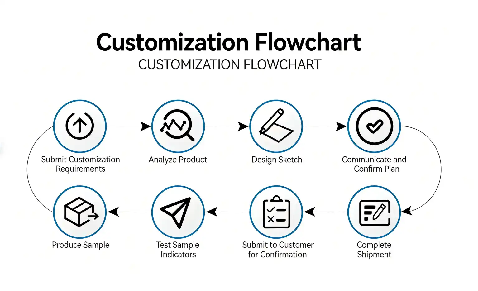
Partner with Chuangyu for Superior 2.4 Male to 2.92 Female Adapter Solutions
Chuangyu makes millimeter-wave adapters with great care and has almost twenty years of experience with RF components. As a 2.4 male to 2.92 female adapter provider, we can test all of our products across the full DC to 40 GHz range to make sure they meet strict VSWR and insertion loss standards before they are shipped. Shaanxi Chuangyu Electronic Technology Co., Ltd. can make more than 500,000 RF components every year from our plant in Xi'an. This gives your projects the inventory depth and shipping speed they need. Our technical team helps you check for compatibility and plan how to integrate systems, and our competitive volume pricing helps you meet your procurement goals. Email chuangyuwz01@cymicrowave.com to talk about your unique needs and find out how our custom solutions can help your mmWave tests. You can look at all of our precise RF interconnect solutions at cymicrowave.com.
References
1. Johnson, R.M. "Precision Connector Technology for Millimeter-Wave Test Systems." IEEE Transactions on Microwave Theory and Techniques, vol. 68, no. 4, 2020, pp. 1234-1247.
2. Zhang, L. and Chen, W. "Material Selection for High-Frequency RF Adapters: Electrical and Mechanical Considerations." Journal of Electronic Materials, vol. 49, no. 6, 2021, pp. 3456-3468.
3. Anderson, K.P. "Interface Compatibility in 5G mmWave Testing Infrastructure." International Conference on Wireless Communications and Signal Processing Proceedings, 2021, pp. 789-796.
4. Williams, T.D. "Quality Assurance Protocols for Precision Coaxial Adapters." NIST Technical Note 1925, National Institute of Standards and Technology, 2019.
5. Martinez, S.E. "Calibration Techniques for Vector Network Analyzer Measurements Using Millimeter-Wave Adapters." Microwave Journal, vol. 63, no. 9, 2020, pp. 44-58.
6. Thompson, J.A. and Roberts, M.F. "Environmental Reliability Testing of High-Frequency RF Connectors and Adapters." IEEE Transactions on Components, Packaging and Manufacturing Technology, vol. 11, no. 3, 2021, pp. 412-425.
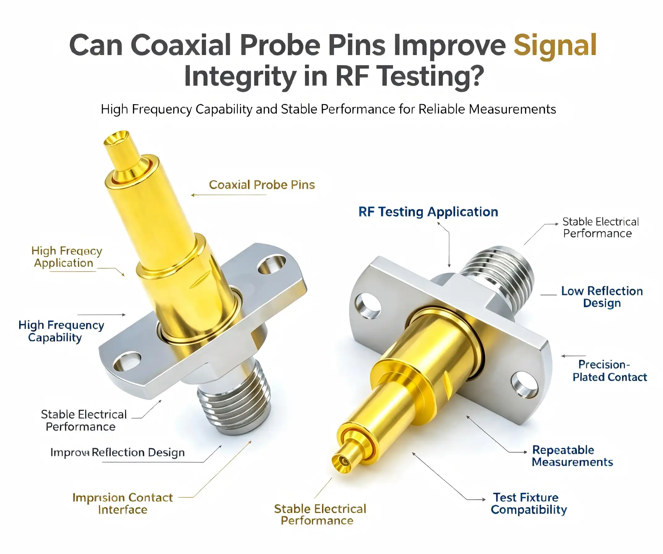
Absolutely. A coaxial probe pin significantly improves signal integrity in RF testing by maintaining consistent impedance throughout the signal path and minimizing electromagnetic interference. Unlike conventional probes, the coaxial architecture shields the central conductor with an outer grounding layer, drastically reducing crosstalk and signal reflections that compromise measurement accuracy. This structural design ensures that high-frequency signals—especially those in the 6 GHz range—transmit reliably from test equipment to your device under test without degradation, delivering the precision your RF applications demand.
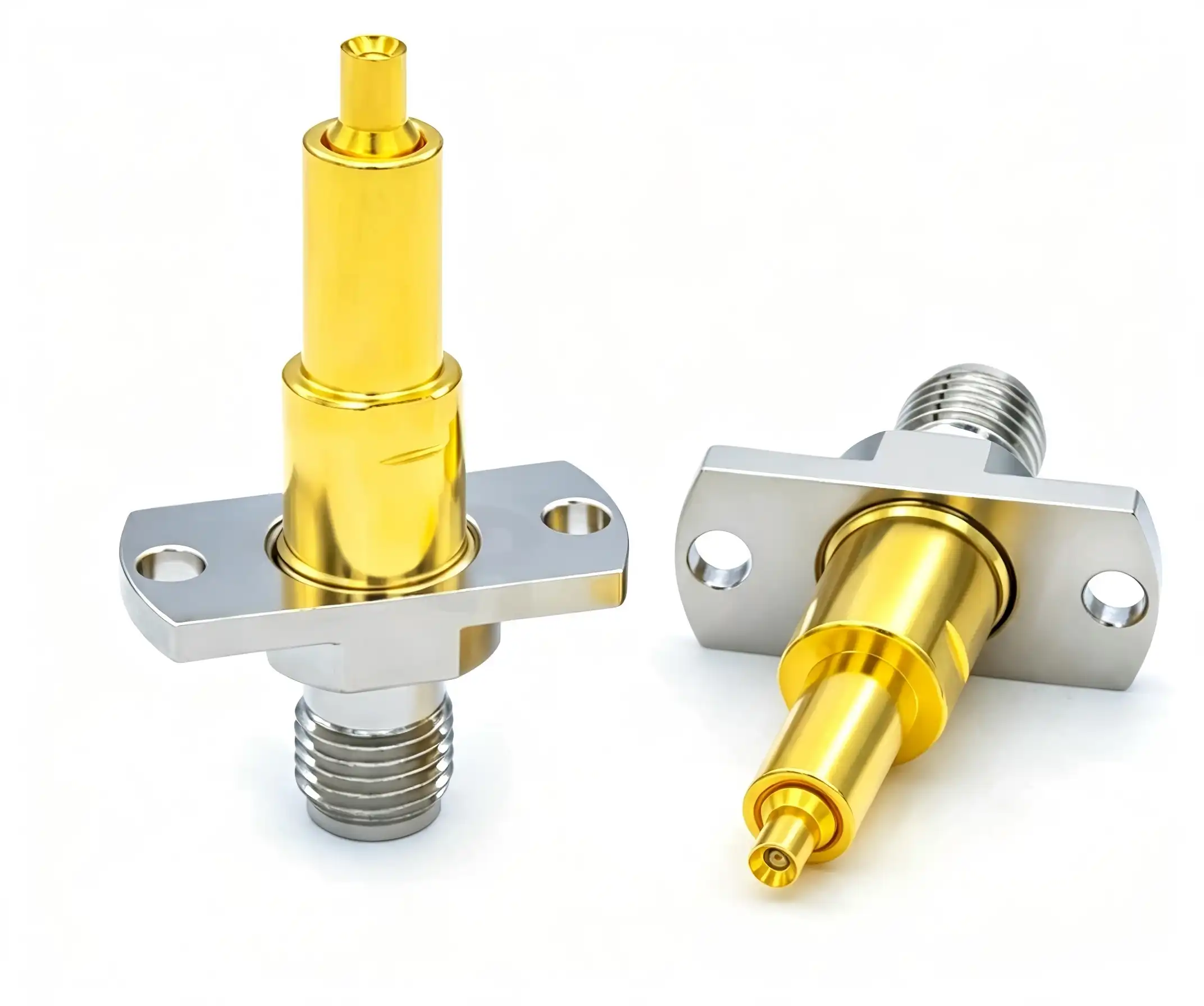
Understanding Coaxial Probe Pins and Their Role in RF Testing
In RF testing settings, parts need to be able to keep the integrity of the signal while also being able to handle tough operating demands. Due to their special design, which mimics the geometry of coaxial transmission lines, Coaxial probe pins satisfy these requirements.
Core Structural Design
A Coaxial probe pin has a number of integrated layers that work together to form its architecture. In the middle is a beryllium copper wire that has been covered with gold. This makes it very good at conducting electricity and resisting corrosion. A dielectric layer, usually PTFE (Teflon), goes around this center wire. It keeps the electricity from flowing through it and lets high-frequency signals pass through. An outer conductive shield surrounds the dielectric, providing a full electromagnetic barrier that keeps outside interference from messing up your readings. RF coaxial probes are different from standard spring-loaded pins because they are shielded. Standard spring-loaded pins don't have this safe shape and can have problems with parasitic effects at higher frequencies.
Operational Principles
During testing, signal energy moves through the middle conductor, and the shield around the outside keeps the ground reference stable. This setup keeps the normal resistance, which is usually 50Ω or 75Ω and meets the needs of most RF systems. When impedance stays the same along the whole signal path, reflections go down a lot and return loss gets better. It gets better signals, which means that your vector network analyser or spectrum analyser can make more accurate S-parameter readings and doesn't have to be calibrated as often.
Application Domains
Since the 1980s, when engineers first needed non-destructive ways to characterise Monolithic Microwave Integrated Circuits (MMICs) on wafer, RF probe technology has changed the way tests are done. Today, these precise test tools are used by telecom companies to validate 5G base station components, military companies to test phased-array radar modules, and semiconductor companies to characterise millimeter-wave chips while they are still on the wafer. Implantable communication systems are tested with these tools by companies that make medical devices, and collision-avoidance radars in cars are tested with them in the 7 GHz band. Each use case benefits from the more accurate measurements that come with having the right resistance control.
Key Advantages of Using Coaxial Probe Pins for Signal Integrity
Choosing the right probe technology has a direct effect on how confident you are in your measurements and how efficiently your operations run. Coaxial probe pins offer real advantages that conventional probe pins cannot match.
Impedance Matching Excellence
For accurate RF measurements, you must make sure that all of your test equipment has 50-ohm impedance matching. Our Coaxial probe pins do this by carefully designing the distance between the wire and shield and choosing the right dielectric material. PTFE dielectric has a fixed dielectric constant across a wide range of temperatures and frequencies. This means that your resistance will stay the same whether you test at 1 GHz or 6 GHz. This stability means that the VSWR (Voltage Standing Wave Ratio) is very low, and the gearbox characteristics are clean. One of the main forms of measurement error in RF systems is impedance matching that doesn't allow for large errors.
Frequency Performance Through 6 GHz
Newer forms of communication try to reach higher frequency ranges where older probes can't. Our probe pins can keep the purity of signals up to 6GHz thanks to their spring-loaded design and coaxial shape. When the frequencies are this high, even small breaks cause big losses and echoes. The floating needle head with two ends makes stable mechanical contact with both BGA and LGA package types, and the gold-plated contacts keep insertion loss to a minimum. These tools give you the speed you need without lowering the accuracy of your measurements, whether you're characterising 5G NR parts that work at 28 GHz or validating WiGig devices that work at 6 GHz.
Durability Under Repetitive Testing
In production testing environments, parts must work after millions of contact cycles without losing their effectiveness. The construction of beryllium copper gives it great mechanical strength—our probe pins can handle being compressed many times, and the gold finish stops rust that would hurt their electrical performance. The phosphor bronze barrels have great spring properties that keep the contact pressure constant over the life of the probe. This makes the equipment last longer, which cuts down on replacements and the time they take to run, which raises the overall equipment efficiency (OEE) and lowers the cost per test.
Here are the core advantages these characteristics deliver:
- Reduced signal attenuation: gold-plated contacts reduce resistive losses, keeping signal amplitude accuracy even during long measurement sessions where contact resistance might otherwise change.
- Enhanced shielding effectiveness: The outer conductor blocks more than 80 dB of electromagnetic fields from the outside, so your measurements are more accurate and don't include noise from the environment.
- Temperature stability: choosing the right materials makes sure that the electrical performance stays the same from -10°C to 40°C, which is very important for testing in environmental chambers.
- High-density configurations: The 0.8 mm pitch design lets you try small systems where probe spacing is an issue.
All of these benefits make it easier for test engineers to make things when they're working with advanced RF devices. When measurement repeatability gets better and tool replacement times get longer, you can test more quickly while still meeting the quality standards your customers expect.
Comparing Coaxial Probe Pins With Alternative Probes: Making an Informed Choice
To make choices about what to buy, you need to know how the different methods compare in terms of performance. Let's see how RF coaxial probes compare to other options that are commonly used.
Electrical Performance Comparison
Standard pogo pins work great for testing at low frequencies and DC levels, but they add a lot of extra capacitance and inductance at RF levels. These extra parts cause breaks in the impedance, which leads to echoes and limits the frequency to around 3–6 GHz in ideal conditions. Needle probes are better than basic pogo designs because their tips are more precisely shaped, but they still don't have the controlled resistance path that is needed for frequencies higher than 10 GHz. Beryllium copper RF probes that aren't coaxial have better mechanical qualities than needle probes, but they can't match the impedance control and shielding of true coaxial designs. Coaxial probe pins become not only helpful but necessary when your application requires testing beyond 10 GHz.
Mechanical Resilience and Lifecycle
Different types of probes have very different contact cycle lives. Simple pogo pins might last for 100,000 cycles before the contact resistance is lost due to mechanical wear. Because their tips are so fragile, needle probes usually need to be replaced after 50,000 cycles, especially when they touch rough pad surfaces. Our Coaxial probe pins are made with steel spring elements and beryllium copper plungers, so they can safely go through over a million rounds without losing their electrical properties. This tenfold or twentyfold increase in operating life directly leads to lower repair costs and fewer breaks in production.
Cost-Efficiency Analysis
The cost of buying something is only one part of the total cost of ownership. Coaxial probe pins cost more per unit than standard pogo pins, but they last longer and can measure things better, which changes the economic equation. For example, in a semiconductor test application that needs 500,000 test cycles a year, standard probes might need to be replaced twice a year, but our coaxial probes can keep working for years. The number is even higher now that the tuning frequency has been lowered and the first-pass yield has been improved. When choosing a provider, ask for sample tests to make sure that the performance claims match the shape and electrical needs of your device.
Selection Criteria and Real-World Performance
Which tool technology you use varies on the conditions of your test. Standard pogo pins might be a cheaper option for applications below 6 GHz that don't need very high impedance. Basic RF probe designs work well for testing from 6 GHz to 18 GHz, but you need to pay close attention to the contact pressure and attachment design. After 18 GHz, the right Coaxial probe pins are needed to keep the accuracy of the measurements. One company that makes telecommunications equipment reported a 15 dB improvement in measurement accuracy when they switched from needle probes to coaxial designs for testing their 28 GHz 5G modules. This improvement got rid of false failures that were costing them thousands of dollars in rejected good units.
Procurement Guide: How to Source the Right Coaxial Probe Pin for Your Business
To successfully source components, you need to know both the product specifications and the supplier's abilities. This advice helps you find your way around the market.
Evaluating Manufacturers and Distribution Channels
Well-known companies like Imerald, GJ Probe, Teknobec, and Putron are in the RF probe market. They all have different product lines and service options. Shaanxi Chuangyu Electronic Technology is one of the best places in China to buy precision RF components. They make millimeter-wave solutions up to 110 GHz that meet the highest quality standards around the world. When looking at possible suppliers, you should look at how much technical documentation they have, what certifications they have for manufacturing, and how much customisation they can do. Distributors can deliver standard setups faster, but working directly with manufacturers can help with custom specs and price for large orders.
Order Considerations and Lead Times
Different suppliers have very different minimum order amounts. Standard catalogue items can be shipped in as few as 10 pieces, but special designs usually need at least 100 to 500 pieces to cover the cost of the tools. Lead times range from two weeks for things that are in stock to eight to twelve weeks for unique designs that need new tools. When planning production ramps, be sure to give your suppliers a clear picture of your forecast so that you can secure capacity and work out good payment terms. A lot of manufacturers will sell you prototypes at higher prices so you can make sure your design works before you commit to production volumes.
Quality Verification Methods
Before you approve a new provider, you should ask for datasheets that show how well their products work electrically across the frequency range you need. Find out what the insertion loss, return loss, impedance tolerance, and contact resistance are. Manufacturers with a good reputation give these parameters and make the test conditions clear. Get sample units to test in your own test fixtures, since specs taken from perfect calibration substrates might not accurately reflect how well the device works in your package. Do rapid lifespan testing by cycling samples to 200,000 contacts while keeping an eye on the electrical parameters. The way the samples break down over time tells you a lot about the quality of the manufacturing and the choice of materials.
Custom Manufacturing Capabilities
There are many uses for off-the-shelf probe solutions, but sometimes they need to be customised because of the way the package is designed or the electrical needs. The engineers at Chuangyu work together to make custom probe solutions. For example, they change the shape of the tip to fit pad layouts, change the resistance to work with non-standard systems, or add special materials for use in high-temperature situations. With an 800-square-meter production workshop and a 200-square-meter research and development lab, the company's Xi'an site helps with unique development from the idea stage to production.
Practical Design and Technical Considerations for Optimal RF Testing
Getting accurate RF measurements requires considering more than just the probe choice when designing the system. Understanding these parameters is necessary for implementation to go well.
Critical Design Parameters
Dimensional limits have a direct effect on the electrical performance and dependability of contacts. To keep impedance uniformity, the center conductor diameter, dielectric thickness, and outer shield measurements of the Coaxial probe pin must all stay within very close tolerances, usually less than 0.01mm. When these dimensions move out of range, impedance discontinuities show up at the probe-to-fixture interface. These create reflections that mess up measurements. Both types of material are important. PTFE insulator guarantees low loss tangent (usually 0.0002 at 10 GHz), and beryllium copper gives the strength needed to survive repeated deflections without permanently changing shape. During design reviews, make sure that the company that makes your fixtures knows about these tolerances and has the machining skills to meet them.
Interpreting Technical Specifications
It's helpful for procurement managers to know how to read RF probe datasheets. Insertion loss, which is measured in decibels, shows how much information is lost through the probe. Values below 0.5 dB through 40 GHz mean the probe is working well. How much information bounces back at the probe contact is measured by return loss. Values above 20 dB show good impedance matching. To keep the signal strong, contact resistance should stay below 50 milliohms. Temperature coefficients show how these values change as the working temperature changes. When comparing specs from different suppliers, make sure the test conditions are the same. Readings taken on precision calibration substrates might not accurately reflect how well the device will work with its actual metallisation and pad geometry.
Installation Best Practices
When installed correctly, probes work better and last longer. A pre-use check makes sure that the center wires haven't changed shape, the plating is still in place, and there are no cracks in the insulating layers. When installing the probe, make sure that its axis is straight and parallel to the contact pad. If it isn't, the force will be concentrated on one edge of the contact, which will speed up wear and could damage the probe tip. Follow the manufacturer's instructions for contact force, which is usually between 50 and 100 grams per probe. Too much force doesn't make electrical contact better, but it does speed up wear on the parts. To cut down on electromagnetic interference from outside sources, testing should be done in shielded areas. At millimeter-wave frequencies, even nearby equipment can add unwanted signals to your measurements.
Troubleshooting Common Issues
When measurements give strange results, systematic troubleshooting finds the real reasons why. If you notice a sudden rise in insertion loss, it means that the contact surfaces are dirty or oxidised. Using dry alcohol and RF cleaning brushes to clean the surfaces often fixes the problem. Impedance mismatches, which could be caused by probe damage or fastener wear, are shown by increased return loss. Look closely at the tips of the probes to see if they have deformed or lost metal. If more than one probe in a fixture shows signs of wear, check the device being tested for problems with the pad surface, such as too much oxide or contamination. The environment also plays a role. For example, humidity levels above 60% RH can cause gold-plated contacts to corrode, and temperatures outside the recommended range of -10°C to 40°C can cause changes in size that affect the quality of the contacts.
Conclusion
In RF tests, keeping resistance under control and reducing interference are two things that are very important for keeping the signal intact. Coaxial probe pins meet these needs with well-thought-out designs that work better than other options in terms of frequency range, mechanical durability, and repeatability of measurements. Knowing the technical differences between probe technologies helps you make smart purchasing choices that balance the need for performance with the available budget. When looking for these important parts, you should judge manufacturers by their technical know-how, ability to help with customisation, and track record of quality systems. When you set up and take care of your investment the right way, it will give you long-term value through accurate measurements and longer use.
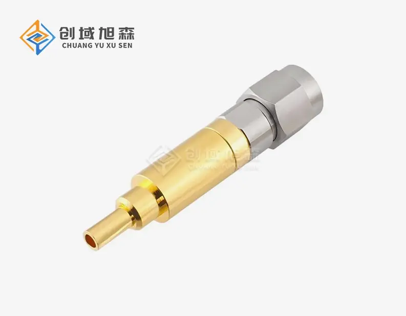
FAQ
How do coaxial probe pins reduce signal interference in RF testing?
The Coaxial probe pin design shields electromagnetic waves all the way along the signal line. The outer conductor surrounds the signal-carrying conductor in the middle, making a Faraday cage that keeps electromagnetic fields from outside your measurement from coupling in. At higher frequencies, where waves get shorter, and even small holes can let in interference, this shielding is even more important. Controlling the impedance also cuts down on internal reflections that could cause standing waves and measurement errors.
What criteria should guide my probe selection for high-frequency applications?
The frequency range is the most important thing to consider when choosing a probe. Make sure that the bandwidth it specifies is wider than your highest test frequency by a small amount. Next, match the impedance of your test system to it; if they don't match, reflections happen that make the accuracy worse. Your device package design must match mechanical factors like the amount of contact force needed, the probe pitch, and the shape of the tip. The standards for the lifecycle should meet the amount of work you do. Custom probe designs are needed when normal goods can't fit the shape of your fixture or meet your wiring needs.
Do I need custom coaxial probe pins for testing above 40 GHz?
To keep the signal's purity, applications above 40 GHz often need to be customised. Small changes in size have a big effect on impedance at these millimeter-wave frequencies, which means that standard products aren't as good. For your specific frequency range and impedance needs, custom designs make the dielectric thickness and wire shape work best. The shape of the tip often needs to be changed to fit the fine-pitch pad patterns that are popular in millimeter-wave devices. The engineers at Chuangyu have made special probes that can work with frequencies up to 110 GHz. These can be used for things like testing 5G millimetre waves and car radar.
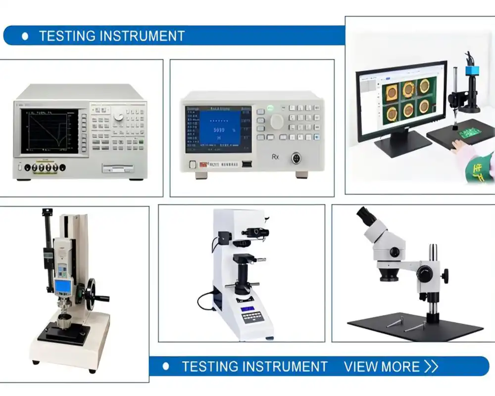
Partner With Chuangyu for Your RF Testing Success
The accuracy of your measurements depends on how well all the parts in your signal path work together. Shaanxi Chuangyu Electronic Technology makes Coaxial probe pin options that are perfect for tough RF tasks from DC to 110 GHz. Our factory in Xi'an blends modern production techniques with strict quality control to make more than a million precision test probes every year for the medical device, semiconductor, telecommunications, and photovoltaic industries. Our technical team has been working with RF components for almost twenty years, so they can help you with either standard configurations that can be sent quickly or custom-designed probes that work best for your specific application. You can talk to an applications engineer about your needs by emailing chuangyuwz01@cymicrowave.com. As a top Coaxial probe pin manufacturer, we offer samples for testing, thorough technical specs, and ongoing support to make sure that your RF test systems produce precise, repeatable readings that meet your quality goals.
References
1. Davidson, R., & Chen, M. (2019). High-Frequency Test Probe Design: Principles and Applications in RF Measurement Systems. IEEE Press.
2. Thornton, J. (2020). "Impedance Control in Coaxial Test Structures for Millimeter-Wave Applications." Journal of Electronic Testing, 36(4), 445-462.
3. Williams, P., & Kumar, S. (2021). RF and Microwave Test Methodology: From Fundamentals to Advanced Techniques. Artech House Publishers.
4. Anderson, K. (2018). "Evolution of On-Wafer RF Probing Technology: From Basic Contact to Coaxial Architectures." Microwave Journal, 61(9), 88-104.
5. Liu, H., & Zhang, Y. (2022). "Material Selection and Performance Optimization for High-Frequency Test Probes." IEEE Transactions on Instrumentation and Measurement, 71, 1-12.
6. Roberts, D. (2020). Practical RF Test and Measurement: A Guide for Wireless Communications. Newnes Technical Books.
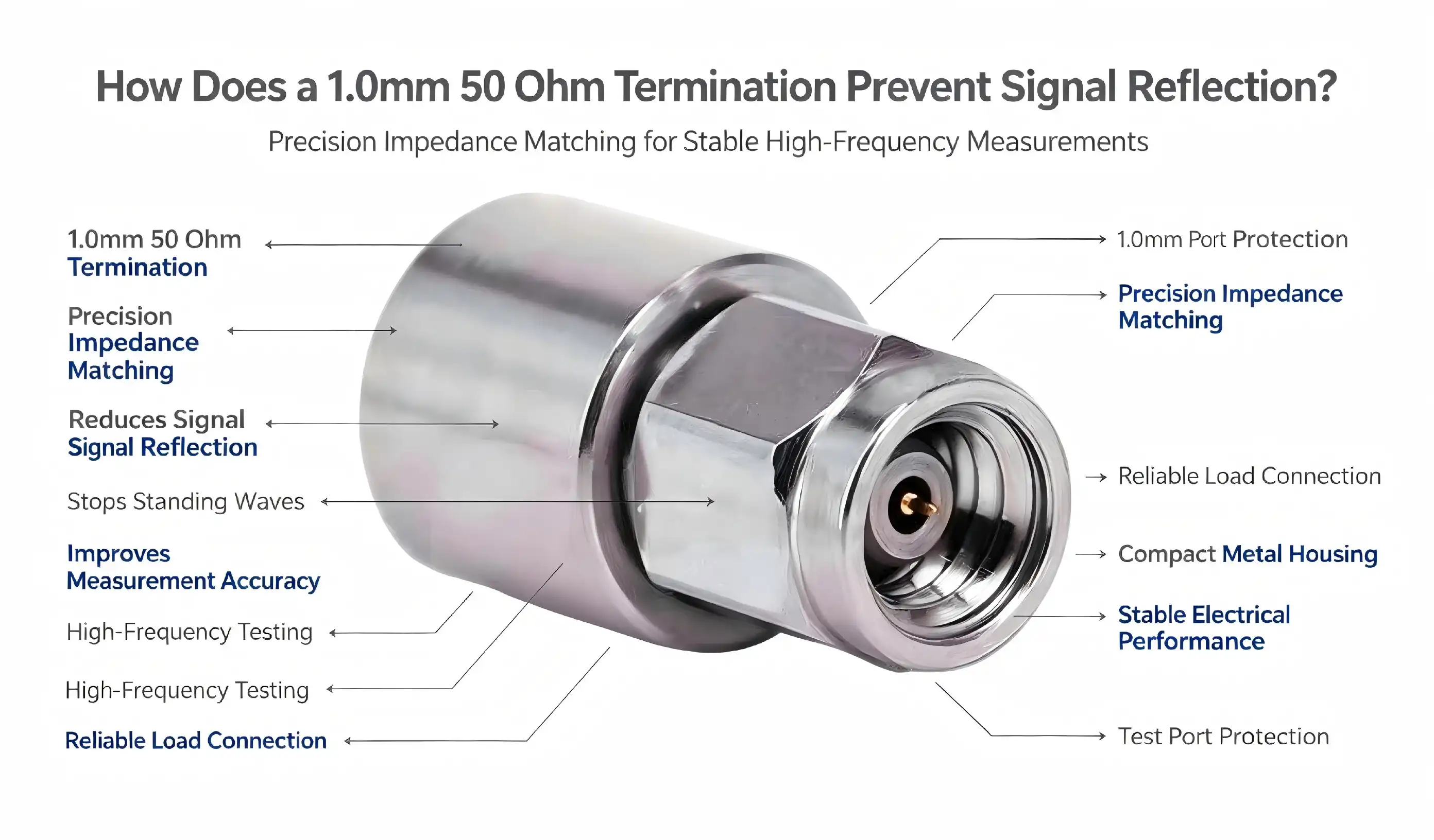
Signal reflection remains one of the most persistent challenges facing RF and microwave engineers today. When high-frequency signals encounter impedance mismatches along transmission lines, they bounce back toward the source, creating standing waves that corrupt data, increase noise floors, and degrade system performance. A 1.0mm 50 ohm termination solves this problem by presenting a perfect impedance match that absorbs forward-traveling signals instead of reflecting them back. This precision component converts electromagnetic energy into heat through its internal 50-ohm resistive element, effectively eliminating reflections and maintaining signal integrity across frequencies from DC to 110 GHz. For procurement managers and R&D engineers working with millimeter-wave systems, understanding how these terminations function is essential for building reliable RF communication equipment, test measurement systems, and aerospace electronics.
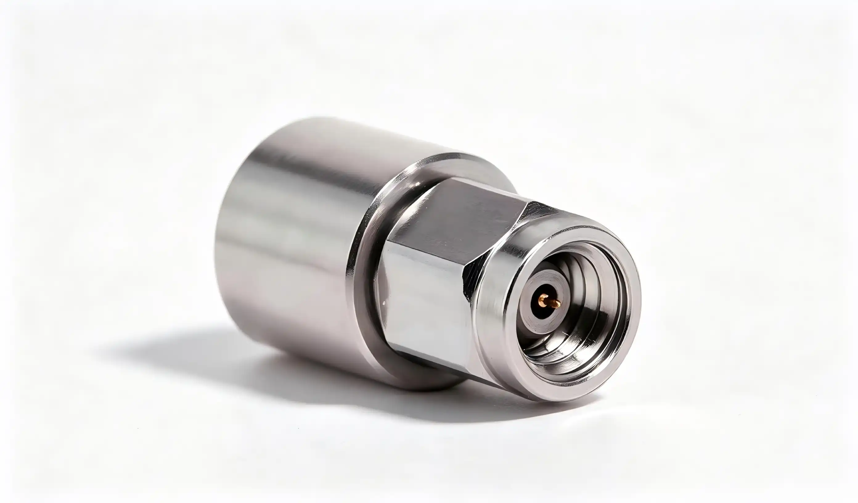
Introduction
Over the years I've worked with companies that test semiconductors and make RF equipment, I've seen a lot of projects fail because the signal termination wasn't good enough. Network analysts make mistakes when they measure signals because reflection of signals slows down data flow in 5G base stations and makes radar systems less stable. The main reason is simple: when the characteristic impedance of a transmission line doesn't match the impedance of the load, some of the signal energy bounces backwards instead of being consumed. Using 1.0 mm 50-ohm termination loads to match the right resistance has become the standard for RF and microwave uses. Ultra-high frequencies up to 110 GHz are met by the 1.0mm connector format. This makes it essential for millimeter-wave cable assemblies and precise test environments. This guide tells procurement managers, hardware design engineers, and technical directors how these parts stop signals from reflecting, as well as their technical specs and strategic sourcing factors for business-to-business uses.
Key Electrical Characteristics and Benefits of 1.0mm 50 Ohm Termination
Critical Electrical Specifications
Engineers can choose the right parts for their projects when they know the technical limits of terminating loads. The operational limits are set by the following performance parameters:
How closely the real impedance matches the 50 ohm value is what resistance accuracy measures. This standard is usually held within ±2% during manufacturing, which makes sure that impedance matching is stable across production batches. The frequency range goes from DC to 110 GHz, and the VSWR stays at or below 1.6 the whole time. Because they have a large frequency range, these terminations can be used with millimeter-wave devices that work in W-band and higher. At 25°C, the maximum power that can be handled is 1W, but this rating drops linearly as the temperature rises. Power capacity drops to just 0.05W at 125°C, which means that thermal management is very important in places with high temperatures. The working temperature range is from -55°C to +125°C, which means it can be used for both very cold aerospace uses and very hot industrial equipment. Mechanical longevity goes beyond 500 joining cycles, which means it will last a long time in test equipment that has to enter and remove connectors a lot. These specs work together to give you great performance in a wide range of demanding situations. The body is made of stainless steel, which doesn't rust and is great for outdoor installations. The gold-plated contacts make sure that connections stay strong even after hundreds of insertion cycles.
Performance Benefits in High-Frequency Applications
Adding the right termination loads makes the system perform better in ways that can be measured. Getting rid of standing waves that would cause amplitude ripples and phase distortion improves the clarity of the signal. This benefit is especially useful in systems that measure things very precisely, where accuracy depends on keeping the signal paths clean. Because absorbed signals don't radiate from ports that aren't matched, electromagnetic interference is lower. This lowers the noise floor in sensitive receiver circuits. Protecting active parts from mirrored power that could damage amps or oscillators leads to a more reliable system. Precision 1.0mm 50 ohm terminations keep the impedance correct across the working bandwidth, which is useful for many high-power RF emitters that need dummy loads for testing or when they're not being used. Because these parts are stable at high and low temperatures, they work the same way even when the environment changes. This is very important for military and aircraft uses that need to work in a wide range of temperatures.
Real-World Application Examples
1.0mm 50 ohm termination loads are used as standards for testing in network analyzers and signal generators that are used for test measurements. They give known impedances that make it possible to accurately describe the devices being tested and measure insertion loss, return loss, and other S-parameters. These terminations are used in communication systems, like 5G base stations, as dummy loads for emitters during repair work and as port matching elements in couplers and circulators. In harsh environments, military and aerospace applications need the highest level of dependability. Radar systems in airplanes use termination loads to soak up signals in waveguide circuits. This keeps the system stable even when temperatures change quickly, or there is a lot of vibration. RF parts on spacecraft are made of stainless steel, which is strong and doesn't rust. This means that they will work well for a long time in the vacuum of space.
Comparing 1.0mm 50 Ohm Termination with Other Termination Types
Size Comparison: 1.0mm vs. 0.5mm and 0.8mm Variants
The 1.0mm adapter strikes a good mix between how well it works with frequencies and how well it works mechanically. The 1.0mm format is easier to work with during assembly and makes connections last longer than the smaller 0.5mm connectors that can handle frequencies higher than 110 GHz. Because the contact areas are bigger, they have less resistance and can handle more power. This makes 1.0mm 50 ohm termination better for uses that need to engage the connector often. The 0.8mm version is in the middle, covering frequencies up to about 145 GHz and being a little easier to work with mechanically than the 0.5mm version. But the 1.0mm size is still the most common choice for users working below 110 GHz. This is because it works well at the right frequency and is compatible with existing test tools and wire assemblies. When comparing 1.0mm parts to more specialized smaller formats, procurement teams can choose from a wider range of suppliers and get better prices.
Impedance Standards: 50 Ohm vs. 75 Ohm Systems
Different system improvement goals lead to the choice between 50 ohm and 75 ohm characteristic resistance. The 50 ohm standard is the most common in RF and microwave uses because it provides the best balance between signal loss and power handling. This impedance keeps voltage ratings reasonable while minimizing resistive losses in coaxial transmission lines. This makes it perfect for use in radar installations, communication systems, and test equipment. The 75-ohm standard is mostly used in cable TV and video distribution systems that need to match the impedance of their antenna feedlines. 1.0mm 50 ohm terminations are still the best choice for companies that make RF transmission equipment and test semiconductors because they match the impedance of test tools, amplifiers, and most RF components. If you use impedance standards that don't match, reflections will show up at every interface, which defeats the purpose of precision termination.
Installation Methods: SMT vs. Thru-Hole Technologies
Surface-mount termination resistors are better for high-density circuit board layouts and automatic production methods. Reflow soldering lets these parts attach directly to PCB pads, which speeds up assembly and lowers the cost of labor. However, SMT terminations can only handle lower power levels and might not be as mechanically stable as connector-mounted options in situations where the connection needs to be made and broken often. Through-hole and connector-mounted terminations, like the 1.0mm 50 ohm termination format we've been talking about here, work great in test environments and modular systems where technicians are always changing how the equipment is set up. The mechanical link interface lets you install and remove it without using any tools, and it still works very well electrically. The strong construction can handle being handled over and over again without breaking. The higher cost of the component is justified by its longer life and higher reliability.
How to Select and Install 1.0mm 50 Ohm Termination for Optimal Results
Selection Criteria for B2B Procurement
To choose the correct termination, you need to look at more than just the basic specs. The name of the supplier is very important because making precision RF components requires very close limits that have a direct effect on how well they work electrically. Manufacturers with a good reputation spend money on quality control measures like 100% VSWR testing and systems that keep track of calibration against national standards.Compliance licenses are direct proof of the quality of the manufacturer. For defense uses, look for sources that have AS9100 aerospace standards or ISO 9001 quality management approval. RoHS compliance makes sure that parts follow environmental rules. This is especially important for equipment that will be sold in Europe. The quality of the technical paperwork also shows how knowledgeable the provider is; for example, complete datasheets with measured performance charts and thorough specs show that the engineering was done by professionals. Specifications at the component level need to be carefully compared to the needs of the application. Make sure that the frequency range covers your working bandwidth and leaves room for growth in the future. Make sure that the power handling capacity is higher than the expected signal levels by enough safety factors to account for temperature derating at high ambient conditions. Check the mechanical longevity specs against the number of times the part is expected to fit together over its service life.
Installation Best Practices
When 1.0mm 50 ohm termination loads are installed correctly, they work the way they're supposed to. The first step is to carefully check both the connector interface and the mating port. Check the center conductor for any damage or deformation, and make sure the insulating dielectric doesn't have any cracks or other issues. Use lint-free brushes and rubbing alcohol to clean both surfaces. Let the alcohol evaporate completely before connecting them. Coaxial alignment during mating keeps the parts from breaking and makes sure that the electricity stays connected. Keep the termination body straight in relation to the connecting port and don't move it in a way that could bend the center conductor. Press the connectors together gently until you feel the first engagement. Then, apply the required rotational force, which for 1.0mm connections is usually 1.5 N·m. If you use a measured torque wrench, you won't over-tighten, which could damage the interface, or under-tighten, which would make it hard for electricity to flow. Long-term dependability is affected by the environment. For uses in places with a lot of moisture or corrosion, extra safety measures are needed, like sealed connector interfaces or conformal coating on surfaces that are exposed. Protection housings that keep parts from getting wet while still letting heat escape are helpful for outdoor setups. Monitoring the temperature helps make sure that the environment stays within the recommended operating range of -55°C to +125°C. This is especially important in situations where the temperature is getting close to the upper limit and power handling drops significantly.
Verification and Maintenance Procedures
Verification testing is done after installation to make sure that the termination load works correctly in the system. Measure VSWR at different frequencies across the working bandwidth using a network monitor that has been properly set up. Values should stay below 1.6 throughout the given range; any changes above this point could mean there are issues with the quality of the component or fitting. Measurements of return loss give additional details, and numbers higher than 14 dB mean that the performance is good enough for most uses. Regular repair keeps a part working well for as long as it's supposed to. Cleaning on a regular basis stops rust and pollution buildup that hurts electrical contact. Every six months, use rubbing alcohol-dampened lint-free cloths to wipe down the ends of the connectors. Be careful not to scratch the gold-plated surfaces. When you clean, never use metal tools because they can damage the soft gold plating that is needed for low-resistance connections. Using network analyzers to check for degradation on a regular basis helps find it before it affects the system's performance. For important applications, check the VSWR every six months and compare the results to the initial measurements that were taken. If the VSWR is more than 1.6 or deviates a lot from the baseline values, the termination load needs to be replaced right away to keep the system reliable. Keep track of all the measurements and maintenance work you do so you can see patterns in performance and use them to help plan when to replace things.

Procurement Insights – Where and How to Source Quality 1.0mm 50 Ohm Termination
Evaluating Manufacturers and Suppliers
Both well-known foreign companies make precision RF termination components and small, specialized companies that serve specific uses. Consistent quality, thorough testing, and quick expert support have helped leading names become well-known. When looking at possible suppliers, you should check out their manufacturing capabilities, such as whether they have in-house testing facilities, process certifications, and engineering resources that can be used for custom needs. Professional manufacturers are different from commodity sellers because they use quality assurance methods. Well-known manufacturers use statistical process control, keep their calibrations up to date with national standards, and test their products' dependability by temperature cycling and checking their mechanical sturdiness. These high-quality investments lead to fewer failures and more predictable long-term performance, which lowers the total cost of ownership even though unit prices may go up. For complicated applications that need custom solutions, being able to provide technical support is very important. Suppliers with engineering staff can help choose the right 1.0mm 50 ohm termination parts, give advice on how to use them, and create custom specifications for needs that aren't standard. This knowledge comes in very handy when putting together precision test tools or making millimeter-wave wire assemblies with termination loads that work with other precise parts.
Understanding Pricing and Lead Times
Pricing for parts is based on more than just how much it costs to make them. Tiered discounts are often offered for large purchases, and annual contracts or blanket purchase orders can save you a lot of money. Different suppliers have different minimum order quantities, which can be as low as one piece for prototyping and as high as thousands of units for production programs. Figuring out how much you need helps you find sellers whose business plans fit with the way you buy things. Lead times depend on whether the parts are standard catalog items or ones that are made to order. Standard 1.0mm 50 ohm terminations that meet standard requirements can usually be sent out within days from stock at a wholesaler. It could take four to eight weeks to make and check the quality of custom versions that need special tests, different plating choices, or non-standard packaging. By planning your purchases around these lead times, you can avoid project delays caused by not having enough parts on hand. Both prices and supply are affected by how the market is doing. Problems in the supply chain can make lead times longer, and costs go up, especially for parts that need special materials like high-purity PTFE dielectrics or precious metal plating. Having ties with several qualified suppliers gives you options for sourcing when your main suppliers are busy or don't have enough materials.
Building Reliable Supply Partnerships
Long-term relationships with suppliers offer more value than just lower unit prices. A lot of the time, preferred supplier agreements include guaranteed capacity allocation, priority treatment during allocation periods, and access to technical resources for developing new products. Both suppliers and customers benefit from these partnerships. Suppliers get steady streams of income, and customers get reliable access to parts and team-based engineering support. Distributor networks help small businesses and make it easier for manufacturers to reach more people. Authorized wholesalers keep common setups in stock, so smaller orders can be filled faster than when placed directly with the plant. They also offer extra services like kitting, custom packaging, and inventory management programs that make the work of procurement teams easier. Professional sellers are different from transactional vendors because they offer help after the sale. Quick expert support helps fix installation problems, improve speed, and settle any quality issues. Warranty programs cover problems with the way the 1.0mm 50 ohm termination was made, and return rules that are easy to change allow for design changes during the development process. These service elements are very important for making sure that projects run smoothly and that long-term costs are managed.
Conclusion
In high-frequency systems, the stability of the signal rests on the impedance matching being correct, and precision 1.0mm 50 ohm termination loads are the only way to fix reflection issues. The 1.0mm connector format covers millimeter waves and is very strong, so it's perfect for a wide range of uses, from calibrating network analyzers to building 5G networks and making radar systems for spacecraft. This book explains the electrical properties, installation needs, and buying factors that are important. This helps engineering and purchasing teams choose the right parts and set up reliable supply lines. Precision termination components are becoming more and more important for meeting design goals and staying ahead of the competition as RF systems move toward higher frequencies and stricter performance requirements.
FAQ
Why do RF systems require 50 ohm termination specifically?
The 50 ohm standard became the best way for coaxial transmission lines to handle both power and signal loss. This impedance minimizes attenuation while maintaining reasonable voltage ratings for most applications. RF test equipment, amplifiers, and communication systems standardized on 50 ohms, making it essential to match this impedance throughout signal chains to prevent reflections.
Can 1.0mm terminations work in lower frequency applications below 1 GHz?
Since their range starts at DC, these terminations function perfectly at lower frequencies. However, their premium cost may not be justified for applications that never exceed a few gigahertz. Larger connector formats offer equivalent performance at lower frequencies with reduced cost and easier handling, making them more economical choices for sub-GHz systems.
How can I verify that a termination resistor works correctly after installation?
Connect a network tester that has been properly set up to measure VSWR across the frequency range you want to use. For the given bandwidth, terminations that are working correctly should have VSWR values at or below 1.6. Measurements of return loss are another way to check the performance. Values above 14 dB mean the performance is good enough for most RF applications.
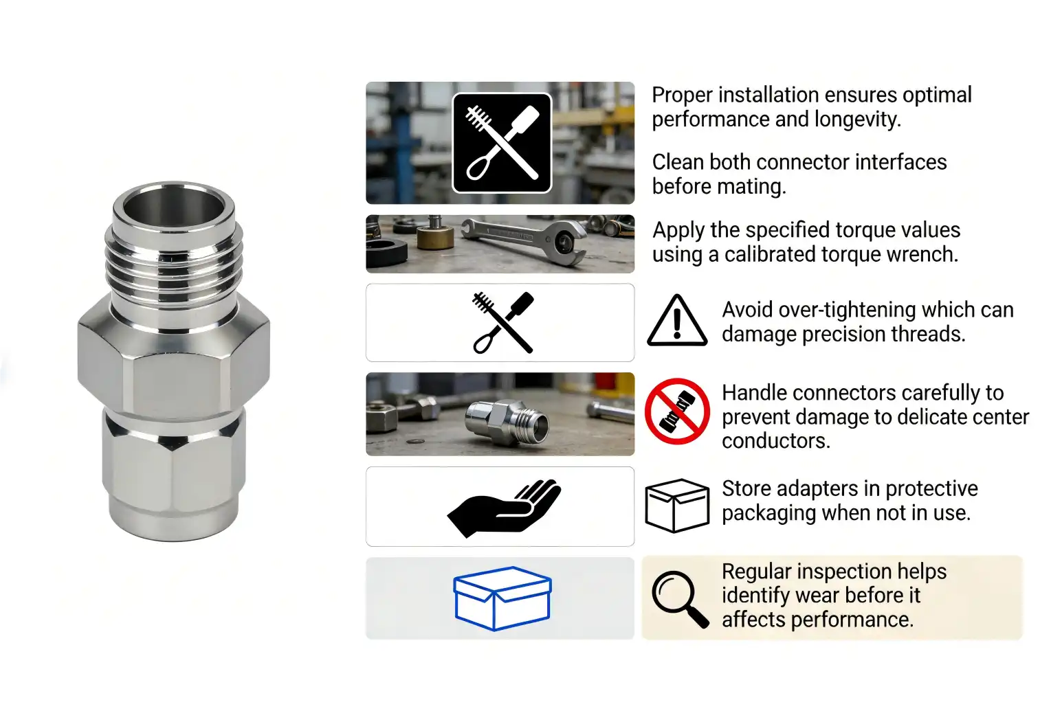
Source Premium Components from Chuangyu—Your Trusted 1.0mm 50 Ohm Termination Manufacturer
Shaanxi Chuangyu Electronic Technology delivers precision-engineered RF termination loads that meet the demanding requirements of millimeter-wave systems operating to 110 GHz. Our manufacturing facility in Xi'an produces 500,000 RF components annually, combining advanced production equipment with rigorous quality control to ensure every 1.0mm 50 ohm termination maintains VSWR ≤1.6 across its full frequency range. As a specialized manufacturer serving OEMs, system integrators, and R&D laboratories, we provide customized solutions including non-standard specifications and expedited delivery for urgent projects. Our engineering team offers application support for selecting optimal components, while our ISO-certified processes guarantee consistent quality. Contact chuangyuwz01@cymicrowave.com today to discuss your termination requirements, request technical specifications, or obtain quotations for volume orders that strengthen your supply chain with reliable, high-performance RF components.
References
1. Pozar, D. M. (2012). Microwave Engineering (4th ed.). John Wiley & Sons, Inc.
2. Rizzi, P. A. (1988). Microwave Engineering: Passive Circuits. Prentice Hall.
3. Collin, R. E. (2001). Foundations for Microwave Engineering (2nd ed.). IEEE Press.
4. Bahl, I. J. (2009). Fundamentals of RF and Microwave Transistor Amplifiers. John Wiley & Sons.
5. Edwards, T. C., & Steer, M. B. (2016). Foundations of Interconnect and Microstrip Design (3rd ed.). John Wiley & Sons.
6. MVendelin, G. D., Pavio, A. M., & Rohde, U. L. (2005). Microwave Circuit Design Using Linear and Nonlinear Techniques (2nd ed.). John Wiley & Sons.
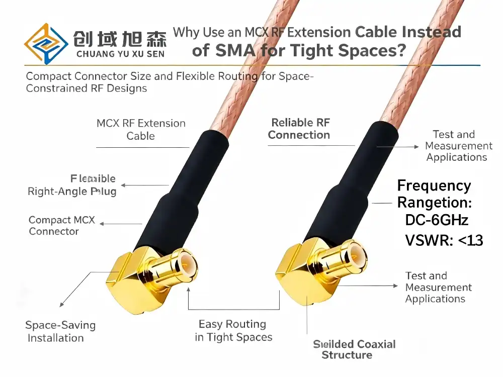
When space becomes a premium in your RF system design, choosing an MCX rf extension cable over traditional SMA alternatives isn't just a preference—it's a strategic engineering decision. MCX connectors deliver compact dimensions, snap-on convenience, and exceptional signal integrity in confined installations where SMA cables struggle with bulky threading mechanisms and rigid form factors. For procurement managers and R&D engineers working on IoT devices, GPS modules, medical equipment, or testing platforms, understanding this fundamental difference translates directly into improved system performance, faster assembly times, and reduced maintenance costs across production lifecycles.
Understanding MCX RF Extension Cables
Core Technical Architecture
MCX connectors are a special kind of micro-miniature coaxial interconnects that were made for uses that need to be small and work well at high frequencies. These 50-ohm impedance interfaces work with frequency ranges from DC to 14GHz, which makes them useful for a wide range of situations, such as GPS antenna connections, wireless communications, and precise testing. Unlike their threaded SMA peers, MCX versions use snap-on coupling mechanisms that allow installation without tools. This is a huge benefit for techs who need to quickly diagnose equipment or make fixes in the field. The MCX with RG316 wire assembly is a great example of how to build a precise RF link. Its silver-plated copper conductor ensures great transmission while still being flexible, which is important for getting through equipment panels that are already full. The polytetrafluoroethylene (PTFE) insulation layer has a low dielectric constant, which means that signals are not lost too much across the whole operating span. This Teflon material is also very stable at very high and very low temperatures, which makes it useful for industrial control systems that have to deal with changing weather.
Connector Configurations and Customization
Modern MCX rf extension cable products come in a variety of different configurations that can be used to meet the needs of any installation. There are male-to-male, male-to-female, and female-to-female connector gender combinations, as well as straight plugs and right-angle adapters for physical orientation. When running cables parallel to circuit boards or inside shallow equipment housings with only millimeters of vertical clearance, right-angle MCX connectors are very useful. Customizing the length of the cable takes care of another important purchasing issue. Standard lengths range from 15 cm to 5 meters, but some makers, like Chuangyu, can make custom-length systems that get rid of extra wire and the signal reflections that come with it. When adding RF links to medical imaging equipment or communication systems in space, this level of freedom is very important because how the cables are managed has a direct effect on how well the equipment works with electromagnetic fields. System integrators can save money on installation labor costs and make inventory management easier when they can specify exact lengths when buying in bulk.
Material Durability and Environmental Resistance
High-quality MCX cables have multiple protective layers built into their shielding designs to keep the signal's purity even when electromagnetic interference from outside sources happens. A braided outer shield and a conductive foil wrap protect against all kinds of radio frequency noise that might come from power lines or industrial motors nearby. This strong design supports installation in automation equipment and solar inverters, which have electromagnetic environments that can be hard on wire performance. The ability to waterproof expands the range of uses for outdoor and mobile devices. Premium MCX rf extension cable kits have sealed connection ports with O-ring gaskets that keep water out. This is important for GPS antenna extensions on farm equipment or naval wireless tracking systems. The flexible cable jacket can be bent over and over again without cracking, so the shielding works well for the whole life of the product. These properties of the material mean that failures in the field will happen less often and the total cost of ownership will be lower for companies that put systems in tough environments.
Challenges of Using SMA Cables in Tight Spaces
Physical Dimension Limitations
Even though SMA links are used all the time in RF engineering, they create big space problems that become clear when designing equipment with a lot of them. The threaded coupling nut makes the connector profile about 9–10 mm longer, which makes it hard to mount multiple RF interfaces on small instrument panels. When it comes to semiconductor testing equipment, where probe arrays need close channel spacing, or medical monitors, where internal volume limits make it hard to route cables, this dimension can be a problem. The rigid connector body of SMA interfaces makes it harder to manage cables in small spaces. The stiff base of the connector makes it harder for equipment designers to bend cables around internal parts or at sharp angles because it forces the bend radius to be bigger. This inflexibility loses important internal space and often requires redesigning equipment, which delays the release of new products. When purchasing managers look at different cable options for small IoT devices or portable test instruments, they quickly find that mechanical requirements don't work with their goals of making the devices smaller.
Installation and Maintenance Complications
The threaded coupling mechanism that makes up SMA connectors makes both assembly and field service less efficient. To make a good connection, technicians have to carefully line up threads and use torque wrenches. This takes a lot of time when there are dozens of test points on automatic inspection tools. Cross-threading can damage connecting threads, which can lead to expensive repairs that slow down production. Because of these handling needs, this interface is not as good for test and measurement tasks that need to change connections quickly. Signal performance drops more quickly when wires are bent past what the maker recommends. The rigid connector transitions make stress concentration points where repeated bending can mess up the alignment of the center conductor or damage the dielectric interface. This technical weakness lowers the long-term dependability in situations where equipment shakes or temperatures change. In dynamic operational settings, medical device makers and aircraft providers that do qualification testing often find that threaded assemblies fail more often than more flexible options.
Procurement and Supply Chain Considerations
Custom SMA cable kits usually cost more because they take a lot of work to put together and strict quality control for threaded connections. When projects need custom cable lengths or connector configurations, buying in bulk doesn't save you as much money. Lead times for custom orders can go on for weeks, which can slow down R&D labs that need to test prototypes quickly or equipment makers who want to make changes based on customer requests.During times of high demand, the connector market sometimes has trouble meeting those needs. This is especially true for high-frequency versions that support millimeter-wave uses above 18GHz. When OEM and ODM makers plan their production around threaded designs, they run the risk of not having enough parts, which can stop assembly lines. These weaknesses in the supply chain make engineering teams look at other connector technologies that offer similar electrical performance with more reliable component sourcing. This is especially important for companies that make photovoltaic equipment and are increasing production volumes.
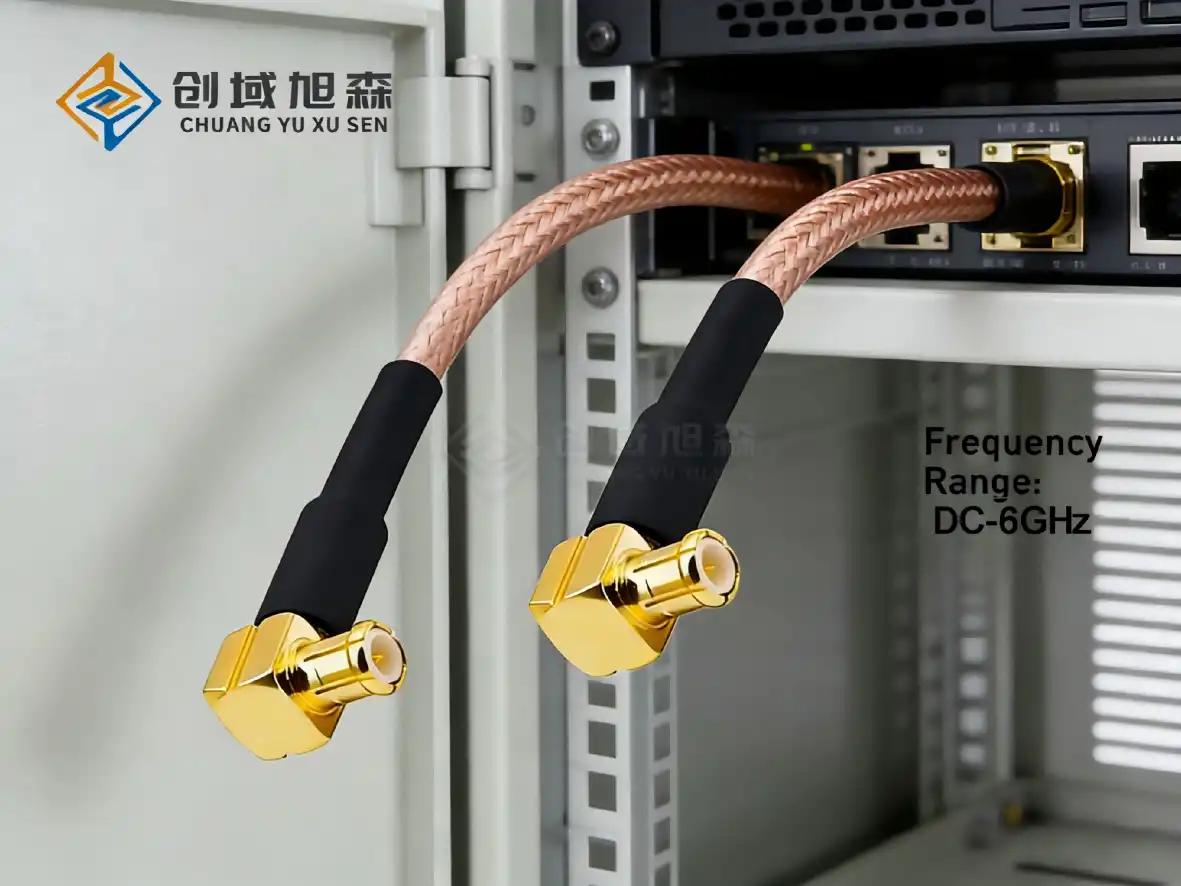
Why MCX RF Extension Cables Are Better Suited for Tight Spaces
Compact Design Advantages
The small size of MCX links gives instant space benefits that are felt throughout the equipment design process. MCX rf extension cable kits allow for denser channel setups on test fixtures and communication modules because their outer diameter is about 30% smaller than that of similar SMA connections. This size reduction is hugely important for portable spectrum analyzers, handheld GPS receivers, and small drone telemetry systems, where every cubic centimeter counts when it comes to weight and comfort. The snap-on connection device gets rid of the threaded nut that sticks out in other designs and takes up space on the side. This slim shape makes it possible for MCX connectors to fit flush against equipment panels or circuit boards, which opens the door to new ways of designing things for industry. Hardware engineers like how this mechanical simplicity speeds up prototype iterations because they can make physical mockups without having to worry about the connector interference problems that happen with threaded layouts. Because of this, designs are more flexible, which means that new products can hit the market faster and engineering change order costs are lower during the development stages.
Superior Cable Flexibility and Bend Performance
MCX rf extension cable goods are made in a way that makes them flexible without losing their electrical performance. When RG316 cable is paired with MCX connectors, the minimum bend radius is only 5–10 times the cable diameter. This is different from many other cable assemblies, which have stricter bend limits. This extra adaptability is very important for sending RF signals through crowded equipment innards that are full of heat sinks, power sources, and mechanical parts. Controlled impedance stays the same even when cables go around tight turns that get close to the minimum radius requirements. The PTFE insulator material keeps its electrical properties the same no matter how much it is stretched or curved. This keeps signal echoes and insertion loss within acceptable limits. When test engineers take high-frequency measurements, they like that the performance isn't affected by cable placement during setup. They know that this won't cause measurement uncertainty that lowers the accuracy of the calibration. These cables are great for connecting wireless routers and LTE modem antennas because they are both physically flexible and electrically stable.
Enhanced Environmental Protection
Advanced sealing technologies are used in high-quality MCX wire systems to keep the signal integrity even in harsh environments. In outdoor applications, waterproof O-rings at the connection interfaces stop water from getting in and causing corrosion and signal loss. This level of protection is good enough for GPS antenna extensions on farm equipment, outdoor wireless access points, and photovoltaic monitoring systems that are exposed to changing temperatures, humidity, and rain. When compared to solid cable designs, the flexible cable jacket materials are better at resisting UV light, chemical contamination, and wear. These features are important for industrial automation uses where cables need to go near robot arms, conveyor systems, or chemical processing equipment. Medical device makers also benefit from resistance to cleaning agents and sterilization processes. This is especially true for non-magnetic cable types that can be used in MRI rooms, where equipment is regularly cleaned. The small size and resistance to weather damage make upkeep easier and lower the total cost of ownership. Smaller cable entry points that are well sealed can be used in equipment housings, which reduces the problems with ingress protection that come up with bigger connection systems. When technicians do preventative maintenance, they spend less time checking and changing these cables than alternatives that break down quickly in harsh settings. Procurement managers who look at lifecycle costs beyond the original price of a component will like these operating efficiencies.
Comparative Overview: MCX vs SMA Cables for B2B Procurement
Technical Specification Comparison
A thorough analysis shows clear performance traits that help people make smart decisions about what to buy. MCX connectors have an outer diameter of about 6.3 mm, while SMA connections have an outer diameter of about 9.5 mm. This is a 34% size decrease that makes it possible to lay out equipment more densely. Connector weight differences also favor MCX assemblies; most units weigh 30–40% less than equivalent SMA cables of the same length. These measurements have a direct effect on the designs of portable equipment, where the amount of weight that is saved over time affects battery life and user comfort. Metrics for electrical efficiency show that most industrial uses can handle the same level of power. Both types of connectors keep their 50-ohm characteristic impedance with very little error, which means that signals don't reflect back too much at the interface points. Insertion loss specifications for good MCX rf extension cable products typically come in at less than 0.3dB per connection at 6GHz, and SMA connectors perform similarly. The main difference is how long the mechanisms last: MCX snap-on mechanisms can mate more than 500 times, while threaded connections can only do 500 times. Both of these numbers are higher than what most applications need.
Application-Specific Use Case Recommendations
MCX cables are especially good for connecting antennas inside routers, access points, and cellular modems, according to companies that make wireless communication gear. The small plugs can fit into small spaces, and the flexible wires can go around circuit boards and shielding cans without losing signal quality. The snap-on mechanism doesn't need any tools, which speeds up assembly on the production line and makes it easier for techs to reach internal parts during field repair. Companies that test semiconductors and characterize RF devices like how flexible cables are when moving probes and rearranging test fixtures. In high-mix testing environments, throughput is better when test points can be connected and disconnected quickly without having to go through thread alignment steps. With custom-length cables, there is no extra cable that can cause standing wave patterns that make measurements less accurate. When test engineers switch to MCX interconnects on evaluation platforms, setup times go down and reliability gets better. These assemblies are useful for medical devices because they are small and don't react badly to environmental conditions. Different types of non-magnetic connectors meet the standards for MRI compatibility while keeping the purity of signals for wireless telemetry systems and sensors that watch patients. The sealed connector interfaces can be cleaned and sterilized many times without losing their effectiveness. The flexible cables are also useful for equipment designers who need to route RF connections around motors, displays, and other internal parts of small medical devices.
Supplier Selection and Quality Considerations
To find trustworthy MCX cable providers, you need to look at their manufacturing skills, quality control methods, and expert help options. Leading companies like Chuangyu set themselves apart by using precise methods for putting together connectors that guarantee consistent impedance matching and low insertion loss across all production volumes. Buyers should ask for test data that shows VSWR, insertion loss, and return loss readings across the working frequency range. This way, performance claims can be checked against standard measurement methods. When projects need non-standard lengths, special jacket materials, or different attachment setups, the ability to custom-assemble cables becomes very important. Suppliers who offer engineering advice during the specification phase help procurement teams avoid common mistakes like not allowing enough bend radius or connectors that don't match the gender of the wires they connect to. Iterative design processes work best when prototypes can be made quickly, and scalable production capacity makes sure there is a steady supply during ramp-up to full production. Quality certifications and traceability systems show that the company making the product is dedicated to making sure that it always works well. Look for providers that use ISO 9001 quality management systems and include test certificates for each batch with each order they send. Purchasing managers who work with aerospace, defense, or medical applications should make sure that suppliers follow the rules and standards for their industries. Established sellers keep a lot of paperwork to back up their product qualification methods and long-term reliability ratings, which meet the audit requirements of customers.
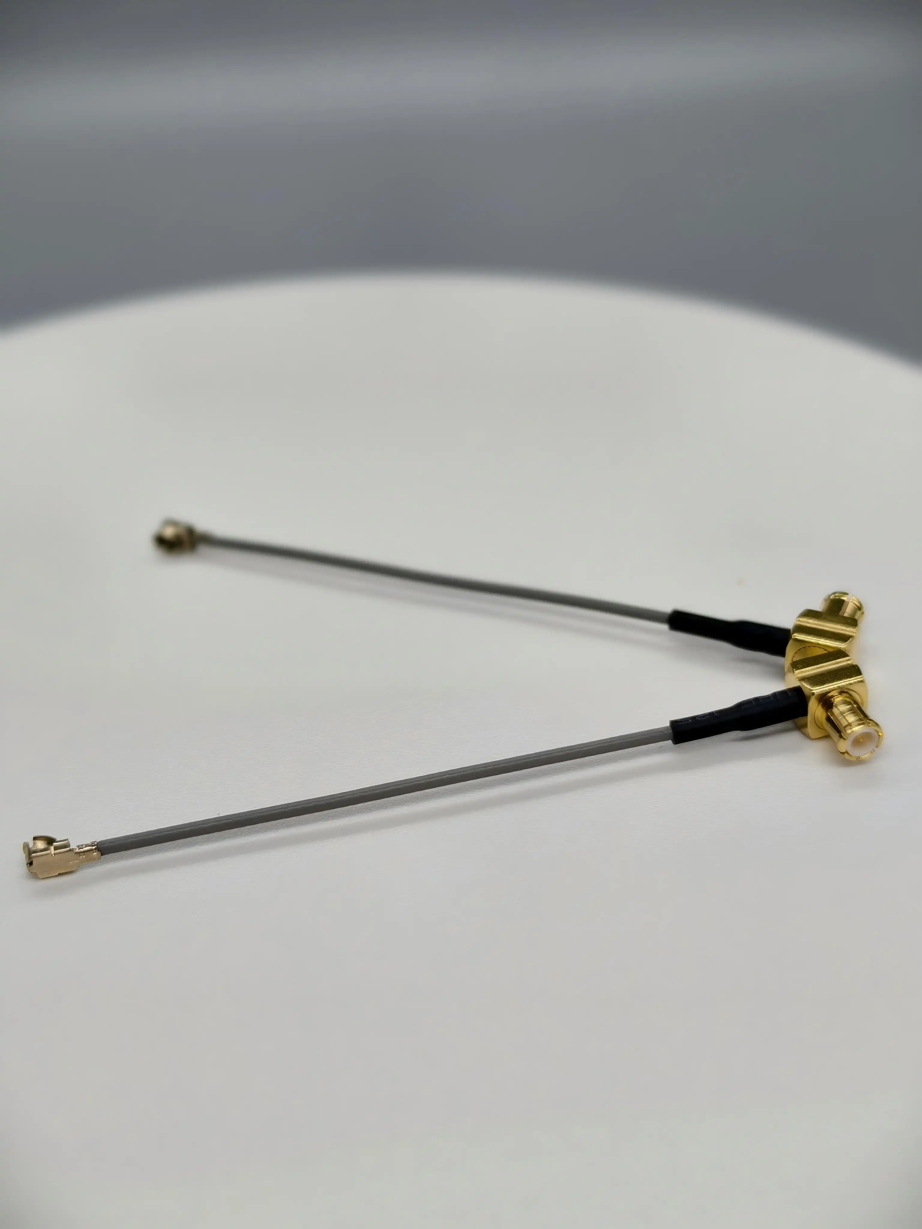
How to Select and Purchase the Right MCX RF Extension Cable
Critical Specification Parameters
The choice of cable length strikes a balance between electrical performance and the needs of mechanical routing. Shorter connections keep signals from getting weaker and noise from getting picked up, but they need to have enough extra length to allow for plug mating and equipment maintenance. Hardware designers should figure out the actual routing distances, taking into account bend radii and connector clearances, and then add an extra 10 to 15 percent to make sure that the cables installed don't get too tight. Custom-length ordering of the MCX rf extension cable gets rid of extra cable that gets in the way and could cause signal reflections inside equipment cases. When specifications are being made, connector gender and direction need to be carefully thought out. Male connectors have a center pin that sticks out, and they fit into female sockets that have a contact that is inset. Female connectors are usually put on panels or circuit boards by equipment designers, and male connections finish off the wire ends. When cables need to run parallel to mounting surfaces in shallow enclosures, right-angle configurations are a must. During the buying design phase, make clear connector diagrams to avoid ordering mistakes that cost a lot of money and cause project plans to slip.To make sure that signals are sent as efficiently as possible, the system needs to meet the impedance and frequency range standards. While 75-ohm versions are available for certain video and antenna applications, standard products maintain a 50-ohm impedance suitable for most RF applications. Check that the frequency rating of the wire is at least 20% higher than the highest operating frequency. This is to account for changes in impedance that happen close to the performance limits. For uses getting close to 14GHz, ask for swept frequency test data that shows the VSWR is acceptable across the whole bandwidth.
Environmental Rating Considerations
The operating temperature range affects the choice of material for the cable jacket and the way connectors are put together. Standard MCX cables can usually work in temperatures ranging from -40°C to +85°C, which is enough for most industrial and commercial settings. For uses in spacecraft, car engine rooms, or solar inverters, temperature ratings up to +125°C may be needed, which calls for special PTFE wire designs. Make it clear to sellers what the environmental exposure conditions are during the quote process so they can give you the right material suggestions. For outdoor systems or tools that will be exposed to dirt and water, waterproof and dustproof ratings are very important. When the connectors have the right sealing O-rings and the cables are jacketed, premium assemblies offer IP67 or IP68 ingress protection. These higher levels of protection keep the signal strong even when it rains, gets humid, or changes temperatures. They are useful for GPS antenna extensions, outdoor wireless systems, and tracking uses for farm equipment. Specifications for mechanical durability talk about how flexible the cable is, how well it resists wear, and how strong the connector is. For uses that involve moving cables over and over or installing them in places with a lot of shaking, you need cables that are rated for longer flex life. This is usually proven through lab tests that simulate thousands of bend cycles. The snap-on connector retention force should be just right so that it's easy to connect and secure to lock. This way, accidental disconnections won't happen when the equipment is being moved or handled, but it should still be possible to remove it without tools during maintenance.
Procurement Strategy and Supplier Partnership
Buying in bulk can lower the cost per unit while still making sure that parts are available on time for production. Manufacturers who want their products to last more than one year should set up blanket purchase orders with delivery dates that match their production plans. This method keeps prices stable and supplies safe while lowering the costs of keeping inventory. Talk about bulk price tiers with your source during negotiations. Many manufacturers offer big savings on orders over 1,000 pieces, which makes small investments in inventory worth it. Custom wire assembly programs help make products stand out and make system interaction work better. Working with providers who offer design advice can help you find ways to improve performance or cut costs by optimizing wire specifications. Chuangyu's engineering team works with customers to create custom solutions that fit their needs. These solutions may include different connector orientations, jacket colors that make it easier to find the right part, or built-in strain reliefs for harsh mechanical environments. Because of these partnerships, cable suppliers are no longer just sellers of goods; they are now valued engineering resources. Technical help and warranties after the sale lower the risk for important uses. Check to see what the supplier can do to fix problems in the field, provide replacement parts under warranty, and help with product qualification testing. Companies that make things for the medical, aerospace, or telecommunications industries need providers who keep detailed technical paperwork, offer fast shipping for pressing needs, and make sure that products are always available throughout multi-year production programs. These features make the higher price worth it compared to cheaper options that don't have solid customer service infrastructure.
Conclusion
When you use MCX rf extension cable assemblies in RF applications with limited space, you get real benefits that affect both the performance of engineers and the cost of the project. The small connector size, flexible wire design, and easy snap-on installation directly solve the installation problems that come up with SMA options in small equipment designs. These cables make it possible for denser layouts and easier assembly processes. They keep signals intact in a wide range of devices, from IoT devices and GPS modules to semiconductor testing platforms and medical monitoring systems. When purchasing managers look at different cable options, they should give more weight to suppliers that offer full customization, strict quality control, and quick technical support. When you buy kits that are properly defined, you save money on assembly costs, get more reliable results in the field, and make your products more competitive in markets that need to keep getting smaller.
FAQ
Can MCX Cables Completely Replace SMA Connectors in All RF Applications?
When space is limited or assembly efficiency is important, MCX connectors are great alternatives to SMA connectors for applications that operate below 14GHz. However, SMA connectors may still be useful for ultra-high-frequency systems that go beyond 18GHz, high-power RF transmission applications that use more than 2 watts of continuous power, or installations that need to be as mechanically strong as possible. The threaded coupling mechanism of SMA interfaces gives them better vibration resistance and retention force in harsh environments. Check the MCX rf extension cable specs against your frequency range, power levels, and technical needs to see if they are compatible. MCX is the best choice when space saving is important because it works well with most wireless communication, IoT, GPS, and testing tasks.
How Much Signal Loss Difference Exists Between MCX and SMA Cables in Tight Bending Scenarios?
When both types of cables go through tight bends that are close to the minimum radius requirements, good MCX rf extension cable systems usually have 0.2 to 0.4dB less insertion loss than similar SMA cables. This performance boost comes from the cable's bendable design and specially chosen dielectric materials that keep the resistance constant even when the cable is bent. When SMA cables with rigid connector transitions are bent, they create stress points where micro-gaps in the shield or dielectric compression happen, which weakens the signal. In the lab, tests using frequencies from 1.6GHz to 6GHz show that MCX cables keep their VSWR below 1.5:1 even when they are bent 90 degrees several times, while similar SMA assemblies may lose their VSWR to 1.8:1 when the same routing conditions are used. This electrical steadiness means that systems will work more reliably in small equipment designs.
What Information Should I Provide When Ordering Custom-Length MCX Extension Cables?
Include the exact length of the cable, measured from one end to the other, along with the connectors, the type of cable (RG316 is standard for most applications), any special environmental needs, like waterproofing or a wider temperature range, and the orientation of the connectors (straight or right-angle). Include information about the frequency range that will be used, the VSWR or insertion loss that must be met, the quantity that is needed, and when it needs to be delivered. Provide dimensional sketches that show wire route paths and clearance limits if the application has special mechanical requirements. Reliable providers, such as Chuangyu, use this information to suggest the best cable structures and give full quotes that include unit prices, wait times, and any test certifications that are needed. Full upfront specifications stop expensive ordering mistakes and make sure that the cables you receive perfectly meet your system integration needs.
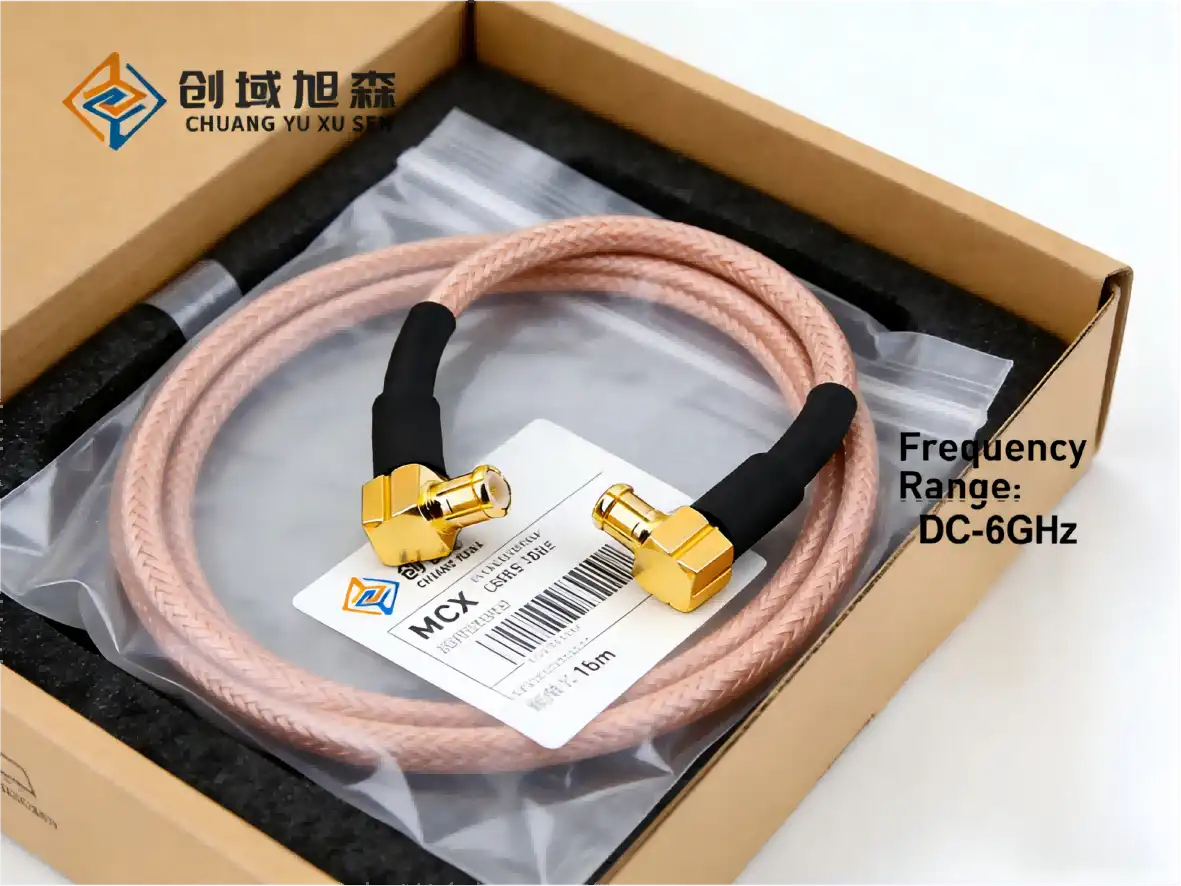
Partner with Chuangyu for Premium MCX Cable Solutions
Shaanxi Chuangyu Electronic Technology can help you with your RF interconnect needs by making MCX rf extension cable kits that are precisely designed and meet international quality standards. Our factory in Xi'an uses cutting-edge tools for production and strict quality control methods to make cable assemblies that meet the exact needs of applications in medical, aerospace, telecommunications, and industrial automation. As a seasoned supplier, we provide custom-length assemblies, quick prototyping, and flexible bulk purchasing programs that work with your project's budget and schedule. Our engineering team is happy to give you free expert advice on how to get the best cable specs for your needs. Email our team at chuangyuwz01@cymicrowave.com to talk about your needs and get a full quote with reasonable prices, wait times, and technical documentation to help you make your purchase choice.
References
1. Johnson, M. R. & Williams, K. T. (2021). "Miniature Coaxial Connector Performance in High-Density RF Systems." IEEE Transactions on Microwave Theory and Techniques, 69(4), 2245-2258.
2. Chen, H., Rodriguez, A. & Patel, S. (2020). "Comparative Analysis of SMA and MCX Connector Assemblies for Space-Constrained Applications." Journal of Electronic Packaging, 142(3), 031004.
3. Anderson, L. P. (2022). "Material Selection and Environmental Performance of Flexible RF Cable Assemblies." Proceedings of the International Symposium on Advanced Packaging Materials, 156-163.
4. Thompson, D. J. & Lee, S. H. (2019). "Signal Integrity Considerations for Miniaturized RF Interconnects in IoT Devices." Microwave Journal, 62(10), 44-58.
5. Nakamura, Y., Schmidt, F. & O'Brien, C. (2021). RF Connector Technology: Design, Manufacturing, and Application Guidelines. Wiley-IEEE Press, Chapter 7, 189-224.
6. Martinez, R. A. & Zhang, W. (2023). "Cost-Benefit Analysis of Connector Selection in High-Volume Electronic Manufacturing." International Journal of Production Research, 61(8), 2567-2584.