- English
- French
- German
- Portuguese
- Spanish
- Russian
- Japanese
- Korean
- Arabic
- Greek
- German
- Turkish
- Italian
- Danish
- Romanian
- Indonesian
- Czech
- Afrikaans
- Swedish
- Polish
- Basque
- Catalan
- Esperanto
- Hindi
- Lao
- Albanian
- Amharic
- Armenian
- Azerbaijani
- Belarusian
- Bengali
- Bosnian
- Bulgarian
- Cebuano
- Chichewa
- Corsican
- Croatian
- Dutch
- Estonian
- Filipino
- Finnish
- Frisian
- Galician
- Georgian
- Gujarati
- Haitian
- Hausa
- Hawaiian
- Hebrew
- Hmong
- Hungarian
- Icelandic
- Igbo
- Javanese
- Kannada
- Kazakh
- Khmer
- Kurdish
- Kyrgyz
- Latin
- Latvian
- Lithuanian
- Luxembou..
- Macedonian
- Malagasy
- Malay
- Malayalam
- Maltese
- Maori
- Marathi
- Mongolian
- Burmese
- Nepali
- Norwegian
- Pashto
- Persian
- Punjabi
- Serbian
- Sesotho
- Sinhala
- Slovak
- Slovenian
- Somali
- Samoan
- Scots Gaelic
- Shona
- Sindhi
- Sundanese
- Swahili
- Tajik
- Tamil
- Telugu
- Thai
- Ukrainian
- Urdu
- Uzbek
- Vietnamese
- Welsh
- Xhosa
- Yiddish
- Yoruba
- Zulu
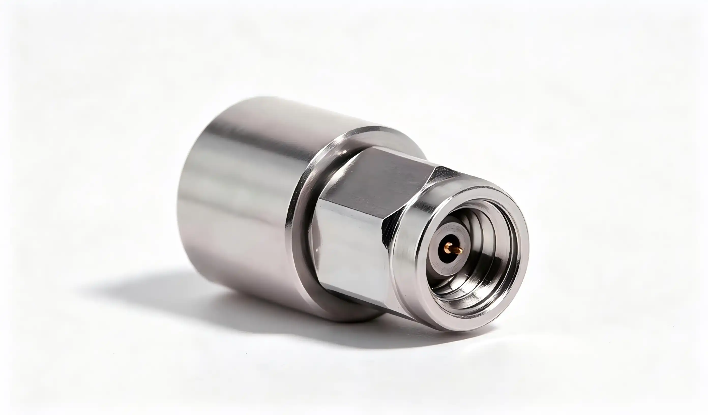
Signal reflection remains one of the most persistent challenges facing RF and microwave engineers today. When high-frequency signals encounter impedance mismatches along transmission lines, they bounce back toward the source, creating standing waves that corrupt data, increase noise floors, and degrade system performance. A 1.0mm 50 ohm termination solves this problem by presenting a perfect impedance match that absorbs forward-traveling signals instead of reflecting them back. This precision component converts electromagnetic energy into heat through its internal 50-ohm resistive element, effectively eliminating reflections and maintaining signal integrity across frequencies from DC to 110 GHz. For procurement managers and R&D engineers working with millimeter-wave systems, understanding how these terminations function is essential for building reliable RF communication equipment, test measurement systems, and aerospace electronics.
Introduction
Over the years I've worked with companies that test semiconductors and make RF equipment, I've seen a lot of projects fail because the signal termination wasn't good enough. Network analysts make mistakes when they measure signals because reflection of signals slows down data flow in 5G base stations and makes radar systems less stable. The main reason is simple: when the characteristic impedance of a transmission line doesn't match the impedance of the load, some of the signal energy bounces backwards instead of being consumed. Using 1.0 mm 50-ohm termination loads to match the right resistance has become the standard for RF and microwave uses. Ultra-high frequencies up to 110 GHz are met by the 1.0mm connector format. This makes it essential for millimeter-wave cable assemblies and precise test environments. This guide tells procurement managers, hardware design engineers, and technical directors how these parts stop signals from reflecting, as well as their technical specs and strategic sourcing factors for business-to-business uses.
Key Electrical Characteristics and Benefits of 1.0mm 50 Ohm Termination
Critical Electrical Specifications
Engineers can choose the right parts for their projects when they know the technical limits of terminating loads. The operational limits are set by the following performance parameters:
How closely the real impedance matches the 50 ohm value is what resistance accuracy measures. This standard is usually held within ±2% during manufacturing, which makes sure that impedance matching is stable across production batches. The frequency range goes from DC to 110 GHz, and the VSWR stays at or below 1.6 the whole time. Because they have a large frequency range, these terminations can be used with millimeter-wave devices that work in W-band and higher. At 25°C, the maximum power that can be handled is 1W, but this rating drops linearly as the temperature rises. Power capacity drops to just 0.05W at 125°C, which means that thermal management is very important in places with high temperatures. The working temperature range is from -55°C to +125°C, which means it can be used for both very cold aerospace uses and very hot industrial equipment. Mechanical longevity goes beyond 500 joining cycles, which means it will last a long time in test equipment that has to enter and remove connectors a lot. These specs work together to give you great performance in a wide range of demanding situations. The body is made of stainless steel, which doesn't rust and is great for outdoor installations. The gold-plated contacts make sure that connections stay strong even after hundreds of insertion cycles.
Performance Benefits in High-Frequency Applications
Adding the right termination loads makes the system perform better in ways that can be measured. Getting rid of standing waves that would cause amplitude ripples and phase distortion improves the clarity of the signal. This benefit is especially useful in systems that measure things very precisely, where accuracy depends on keeping the signal paths clean. Because absorbed signals don't radiate from ports that aren't matched, electromagnetic interference is lower. This lowers the noise floor in sensitive receiver circuits. Protecting active parts from mirrored power that could damage amps or oscillators leads to a more reliable system. Precision 1.0mm 50 ohm terminations keep the impedance correct across the working bandwidth, which is useful for many high-power RF emitters that need dummy loads for testing or when they're not being used. Because these parts are stable at high and low temperatures, they work the same way even when the environment changes. This is very important for military and aircraft uses that need to work in a wide range of temperatures.
Real-World Application Examples
1.0mm 50 ohm termination loads are used as standards for testing in network analyzers and signal generators that are used for test measurements. They give known impedances that make it possible to accurately describe the devices being tested and measure insertion loss, return loss, and other S-parameters. These terminations are used in communication systems, like 5G base stations, as dummy loads for emitters during repair work and as port matching elements in couplers and circulators. In harsh environments, military and aerospace applications need the highest level of dependability. Radar systems in airplanes use termination loads to soak up signals in waveguide circuits. This keeps the system stable even when temperatures change quickly, or there is a lot of vibration. RF parts on spacecraft are made of stainless steel, which is strong and doesn't rust. This means that they will work well for a long time in the vacuum of space.
Comparing 1.0mm 50 Ohm Termination with Other Termination Types
Size Comparison: 1.0mm vs. 0.5mm and 0.8mm Variants
The 1.0mm adapter strikes a good mix between how well it works with frequencies and how well it works mechanically. The 1.0mm format is easier to work with during assembly and makes connections last longer than the smaller 0.5mm connectors that can handle frequencies higher than 110 GHz. Because the contact areas are bigger, they have less resistance and can handle more power. This makes 1.0mm 50 ohm termination better for uses that need to engage the connector often. The 0.8mm version is in the middle, covering frequencies up to about 145 GHz and being a little easier to work with mechanically than the 0.5mm version. But the 1.0mm size is still the most common choice for users working below 110 GHz. This is because it works well at the right frequency and is compatible with existing test tools and wire assemblies. When comparing 1.0mm parts to more specialized smaller formats, procurement teams can choose from a wider range of suppliers and get better prices.
Impedance Standards: 50 Ohm vs. 75 Ohm Systems
Different system improvement goals lead to the choice between 50 ohm and 75 ohm characteristic resistance. The 50 ohm standard is the most common in RF and microwave uses because it provides the best balance between signal loss and power handling. This impedance keeps voltage ratings reasonable while minimizing resistive losses in coaxial transmission lines. This makes it perfect for use in radar installations, communication systems, and test equipment. The 75-ohm standard is mostly used in cable TV and video distribution systems that need to match the impedance of their antenna feedlines. 1.0mm 50 ohm terminations are still the best choice for companies that make RF transmission equipment and test semiconductors because they match the impedance of test tools, amplifiers, and most RF components. If you use impedance standards that don't match, reflections will show up at every interface, which defeats the purpose of precision termination.
Installation Methods: SMT vs. Thru-Hole Technologies
Surface-mount termination resistors are better for high-density circuit board layouts and automatic production methods. Reflow soldering lets these parts attach directly to PCB pads, which speeds up assembly and lowers the cost of labor. However, SMT terminations can only handle lower power levels and might not be as mechanically stable as connector-mounted options in situations where the connection needs to be made and broken often. Through-hole and connector-mounted terminations, like the 1.0mm 50 ohm termination format we've been talking about here, work great in test environments and modular systems where technicians are always changing how the equipment is set up. The mechanical link interface lets you install and remove it without using any tools, and it still works very well electrically. The strong construction can handle being handled over and over again without breaking. The higher cost of the component is justified by its longer life and higher reliability.
How to Select and Install 1.0mm 50 Ohm Termination for Optimal Results
Selection Criteria for B2B Procurement
To choose the correct termination, you need to look at more than just the basic specs. The name of the supplier is very important because making precision RF components requires very close limits that have a direct effect on how well they work electrically. Manufacturers with a good reputation spend money on quality control measures like 100% VSWR testing and systems that keep track of calibration against national standards.Compliance licenses are direct proof of the quality of the manufacturer. For defense uses, look for sources that have AS9100 aerospace standards or ISO 9001 quality management approval. RoHS compliance makes sure that parts follow environmental rules. This is especially important for equipment that will be sold in Europe. The quality of the technical paperwork also shows how knowledgeable the provider is; for example, complete datasheets with measured performance charts and thorough specs show that the engineering was done by professionals. Specifications at the component level need to be carefully compared to the needs of the application. Make sure that the frequency range covers your working bandwidth and leaves room for growth in the future. Make sure that the power handling capacity is higher than the expected signal levels by enough safety factors to account for temperature derating at high ambient conditions. Check the mechanical longevity specs against the number of times the part is expected to fit together over its service life.
Installation Best Practices
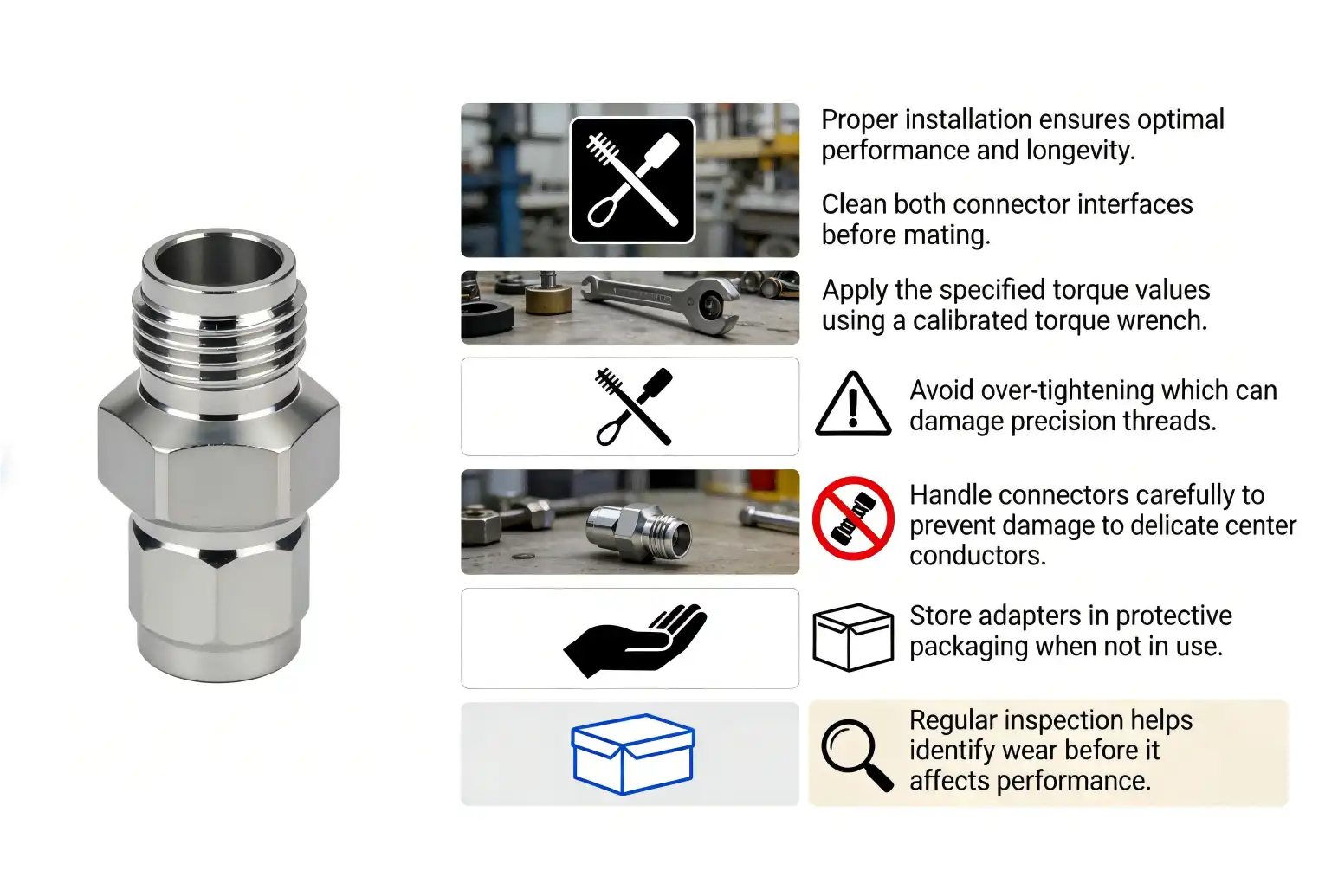
When 1.0mm 50 ohm termination loads are installed correctly, they work the way they're supposed to. The first step is to carefully check both the connector interface and the mating port. Check the center conductor for any damage or deformation, and make sure the insulating dielectric doesn't have any cracks or other issues. Use lint-free brushes and rubbing alcohol to clean both surfaces. Let the alcohol evaporate completely before connecting them. Coaxial alignment during mating keeps the parts from breaking and makes sure that the electricity stays connected. Keep the termination body straight in relation to the connecting port and don't move it in a way that could bend the center conductor. Press the connectors together gently until you feel the first engagement. Then, apply the required rotational force, which for 1.0mm connections is usually 1.5 N·m. If you use a measured torque wrench, you won't over-tighten, which could damage the interface, or under-tighten, which would make it hard for electricity to flow. Long-term dependability is affected by the environment. For uses in places with a lot of moisture or corrosion, extra safety measures are needed, like sealed connector interfaces or conformal coating on surfaces that are exposed. Protection housings that keep parts from getting wet while still letting heat escape are helpful for outdoor setups. Monitoring the temperature helps make sure that the environment stays within the recommended operating range of -55°C to +125°C. This is especially important in situations where the temperature is getting close to the upper limit and power handling drops significantly.
Verification and Maintenance Procedures
Verification testing is done after installation to make sure that the termination load works correctly in the system. Measure VSWR at different frequencies across the working bandwidth using a network monitor that has been properly set up. Values should stay below 1.6 throughout the given range; any changes above this point could mean there are issues with the quality of the component or fitting. Measurements of return loss give additional details, and numbers higher than 14 dB mean that the performance is good enough for most uses. Regular repair keeps a part working well for as long as it's supposed to. Cleaning on a regular basis stops rust and pollution buildup that hurts electrical contact. Every six months, use rubbing alcohol-dampened lint-free cloths to wipe down the ends of the connectors. Be careful not to scratch the gold-plated surfaces. When you clean, never use metal tools because they can damage the soft gold plating that is needed for low-resistance connections. Using network analyzers to check for degradation on a regular basis helps find it before it affects the system's performance. For important applications, check the VSWR every six months and compare the results to the initial measurements that were taken. If the VSWR is more than 1.6 or deviates a lot from the baseline values, the termination load needs to be replaced right away to keep the system reliable. Keep track of all the measurements and maintenance work you do so you can see patterns in performance and use them to help plan when to replace things.

Procurement Insights – Where and How to Source Quality 1.0mm 50 Ohm Termination
Evaluating Manufacturers and Suppliers
Both well-known foreign companies make precision RF termination components and small, specialized companies that serve specific uses. Consistent quality, thorough testing, and quick expert support have helped leading names become well-known. When looking at possible suppliers, you should check out their manufacturing capabilities, such as whether they have in-house testing facilities, process certifications, and engineering resources that can be used for custom needs. Professional manufacturers are different from commodity sellers because they use quality assurance methods. Well-known manufacturers use statistical process control, keep their calibrations up to date with national standards, and test their products' dependability by temperature cycling and checking their mechanical sturdiness. These high-quality investments lead to fewer failures and more predictable long-term performance, which lowers the total cost of ownership even though unit prices may go up. For complicated applications that need custom solutions, being able to provide technical support is very important. Suppliers with engineering staff can help choose the right 1.0mm 50 ohm termination parts, give advice on how to use them, and create custom specifications for needs that aren't standard. This knowledge comes in very handy when putting together precision test tools or making millimeter-wave wire assemblies with termination loads that work with other precise parts.
Understanding Pricing and Lead Times
Pricing for parts is based on more than just how much it costs to make them. Tiered discounts are often offered for large purchases, and annual contracts or blanket purchase orders can save you a lot of money. Different suppliers have different minimum order quantities, which can be as low as one piece for prototyping and as high as thousands of units for production programs. Figuring out how much you need helps you find sellers whose business plans fit with the way you buy things. Lead times depend on whether the parts are standard catalog items or ones that are made to order. Standard 1.0mm 50 ohm terminations that meet standard requirements can usually be sent out within days from stock at a wholesaler. It could take four to eight weeks to make and check the quality of custom versions that need special tests, different plating choices, or non-standard packaging. By planning your purchases around these lead times, you can avoid project delays caused by not having enough parts on hand. Both prices and supply are affected by how the market is doing. Problems in the supply chain can make lead times longer, and costs go up, especially for parts that need special materials like high-purity PTFE dielectrics or precious metal plating. Having ties with several qualified suppliers gives you options for sourcing when your main suppliers are busy or don't have enough materials.
Building Reliable Supply Partnerships
Long-term relationships with suppliers offer more value than just lower unit prices. A lot of the time, preferred supplier agreements include guaranteed capacity allocation, priority treatment during allocation periods, and access to technical resources for developing new products. Both suppliers and customers benefit from these partnerships. Suppliers get steady streams of income, and customers get reliable access to parts and team-based engineering support. Distributor networks help small businesses and make it easier for manufacturers to reach more people. Authorized wholesalers keep common setups in stock, so smaller orders can be filled faster than when placed directly with the plant. They also offer extra services like kitting, custom packaging, and inventory management programs that make the work of procurement teams easier. Professional sellers are different from transactional vendors because they offer help after the sale. Quick expert support helps fix installation problems, improve speed, and settle any quality issues. Warranty programs cover problems with the way the 1.0mm 50 ohm termination was made, and return rules that are easy to change allow for design changes during the development process. These service elements are very important for making sure that projects run smoothly and that long-term costs are managed.
Conclusion
In high-frequency systems, the stability of the signal rests on the impedance matching being correct, and precision 1.0mm 50 ohm termination loads are the only way to fix reflection issues. The 1.0mm connector format covers millimeter waves and is very strong, so it's perfect for a wide range of uses, from calibrating network analyzers to building 5G networks and making radar systems for spacecraft. This book explains the electrical properties, installation needs, and buying factors that are important. This helps engineering and purchasing teams choose the right parts and set up reliable supply lines. Precision termination components are becoming more and more important for meeting design goals and staying ahead of the competition as RF systems move toward higher frequencies and stricter performance requirements.
FAQ
Why do RF systems require 50 ohm termination specifically?
The 50 ohm standard became the best way for coaxial transmission lines to handle both power and signal loss. This impedance minimizes attenuation while maintaining reasonable voltage ratings for most applications. RF test equipment, amplifiers, and communication systems standardized on 50 ohms, making it essential to match this impedance throughout signal chains to prevent reflections.
Can 1.0mm terminations work in lower frequency applications below 1 GHz?
Since their range starts at DC, these terminations function perfectly at lower frequencies. However, their premium cost may not be justified for applications that never exceed a few gigahertz. Larger connector formats offer equivalent performance at lower frequencies with reduced cost and easier handling, making them more economical choices for sub-GHz systems.
How can I verify that a termination resistor works correctly after installation?
Connect a network tester that has been properly set up to measure VSWR across the frequency range you want to use. For the given bandwidth, terminations that are working correctly should have VSWR values at or below 1.6. Measurements of return loss are another way to check the performance. Values above 14 dB mean the performance is good enough for most RF applications.
Source Premium Components from Chuangyu—Your Trusted 1.0mm 50 Ohm Termination Manufacturer
Shaanxi Chuangyu Electronic Technology delivers precision-engineered RF termination loads that meet the demanding requirements of millimeter-wave systems operating to 110 GHz. Our manufacturing facility in Xi'an produces 500,000 RF components annually, combining advanced production equipment with rigorous quality control to ensure every 1.0mm 50 ohm termination maintains VSWR ≤1.6 across its full frequency range. As a specialized manufacturer serving OEMs, system integrators, and R&D laboratories, we provide customized solutions including non-standard specifications and expedited delivery for urgent projects. Our engineering team offers application support for selecting optimal components, while our ISO-certified processes guarantee consistent quality. Contact chuangyuwz01@cymicrowave.com today to discuss your termination requirements, request technical specifications, or obtain quotations for volume orders that strengthen your supply chain with reliable, high-performance RF components.
References
1. Pozar, D. M. (2012). Microwave Engineering (4th ed.). John Wiley & Sons, Inc.
2. Rizzi, P. A. (1988). Microwave Engineering: Passive Circuits. Prentice Hall.
3. Collin, R. E. (2001). Foundations for Microwave Engineering (2nd ed.). IEEE Press.
4. Bahl, I. J. (2009). Fundamentals of RF and Microwave Transistor Amplifiers. John Wiley & Sons.
5. Edwards, T. C., & Steer, M. B. (2016). Foundations of Interconnect and Microstrip Design (3rd ed.). John Wiley & Sons.
6. MVendelin, G. D., Pavio, A. M., & Rohde, U. L. (2005). Microwave Circuit Design Using Linear and Nonlinear Techniques (2nd ed.). John Wiley & Sons.
