- English
- French
- German
- Portuguese
- Spanish
- Russian
- Japanese
- Korean
- Arabic
- Greek
- German
- Turkish
- Italian
- Danish
- Romanian
- Indonesian
- Czech
- Afrikaans
- Swedish
- Polish
- Basque
- Catalan
- Esperanto
- Hindi
- Lao
- Albanian
- Amharic
- Armenian
- Azerbaijani
- Belarusian
- Bengali
- Bosnian
- Bulgarian
- Cebuano
- Chichewa
- Corsican
- Croatian
- Dutch
- Estonian
- Filipino
- Finnish
- Frisian
- Galician
- Georgian
- Gujarati
- Haitian
- Hausa
- Hawaiian
- Hebrew
- Hmong
- Hungarian
- Icelandic
- Igbo
- Javanese
- Kannada
- Kazakh
- Khmer
- Kurdish
- Kyrgyz
- Latin
- Latvian
- Lithuanian
- Luxembou..
- Macedonian
- Malagasy
- Malay
- Malayalam
- Maltese
- Maori
- Marathi
- Mongolian
- Burmese
- Nepali
- Norwegian
- Pashto
- Persian
- Punjabi
- Serbian
- Sesotho
- Sinhala
- Slovak
- Slovenian
- Somali
- Samoan
- Scots Gaelic
- Shona
- Sindhi
- Sundanese
- Swahili
- Tajik
- Tamil
- Telugu
- Thai
- Ukrainian
- Urdu
- Uzbek
- Vietnamese
- Welsh
- Xhosa
- Yiddish
- Yoruba
- Zulu
Modern electronics manufacturing demands precision connections that can withstand millions of test cycles while maintaining consistent electrical performance. SMT Pogo Pins have emerged as the definitive solution for automated assembly lines, combining surface-mount technology with spring-loaded reliability. These compact connectors deliver exceptional durability and precision that traditional through-hole pins simply cannot match. When you face high-volume production demands in RF testing, semiconductor verification, or photovoltaic equipment manufacturing, these spring-loaded connectors provide the repeatable accuracy your quality assurance protocols require, making them indispensable for procurement managers and R&D engineers seeking cost-effective, reliable interconnection solutions.
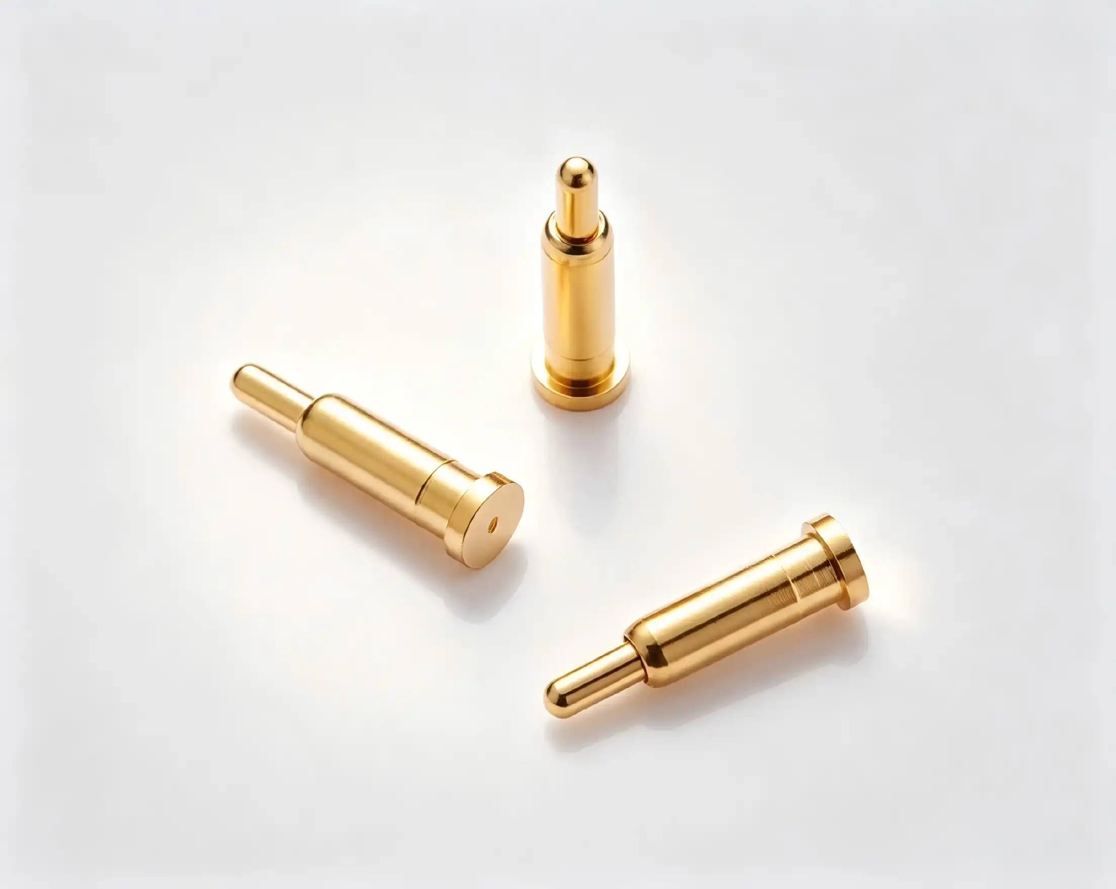
Understanding SMT Pogo Pins and Their Role in Automated Assembly
The way we connect electrical parts in modern factories has changed a lot because of surface-mount technology. SMT Pogo pins that are made to be placed automatically are a big improvement over older connection systems. There are three main parts to these parts: a precisely machined plunger, a high-force spring mechanism, and a strong barrel housing. The plunger makes electrical contact with your PCB or test pad, and the internal spring keeps the compression force the same even after thousands of mating cycles.
Structural Features That Define Performance
The core design of these SMT Pogo pins determines which applications they can handle. The mechanical strength and spring properties of beryllium copper construction are better than those of normal brass construction. Gold plating on contact surfaces protects against oxidation and keeps conductivity stable at all temperatures. To make sure that our parts work with automated pick-and-place equipment used in high-speed assembly lines, we make sure that they have very tight tolerances on their sizes. Stacking height changes from 2 mm to 5 mm when compressed, which lets design engineers find the best board spacing for multi-layer assemblies. Pin counts can be set from a simple single-contact design to a complicated multi-pin array. This allows for a wide range of testing situations, from simple continuity checks to sending high-frequency RF signals. Pitch sizes of 1.27mm, 2.0mm, 2.54mm, and 3.0mm are all standard PCB grid sizes, which makes it easier to integrate into existing product architectures.
Operational Principles in Automated Environments
SMT Pogo pins work perfectly with reflow soldering profiles, while through-hole pins need to be soldered by hand or with a wave of electricity. This flexibility speeds up production and lowers the number of mistakes that happen during building when people do it by hand. The spring-loaded mechanism fixes any PCB warping, thermal expansion, or slight misalignment problems that happen during automated testing. Even if mechanical tolerances change from one production batch to the next, your test equipment will still make good electrical contact. These SMT Pogo pins work great in situations where they need to connect and disconnect many times. The consistent contact force these parts provide is useful for automated test equipment for smartphone batteries, medical device programming stations, and photovoltaic junction box verification systems. The spring system equally spreads mechanical stress, which stops contact fatigue that happens with rigid pin designs after a while of use.
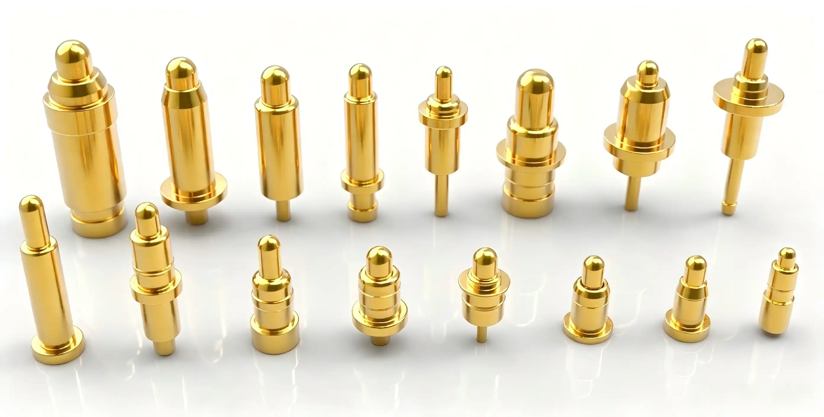
Why SMT Pogo Pins Outperform Traditional Pins in Automated Assembly
In modern manufacturing settings, traditional through-hole connectors have a lot of problems. There are risks of human error in manual soldering, and wave soldering can't handle the high component density needed in modern circuit designs. These problems are completely eliminated by SMT Pogo pins that are made to be mounted on the surface. Pick-and-place machines automatically place these SMT Pogo pins with accuracy better than ±0.05mm, which is much better than what can be done by hand. This level of accuracy directly leads to lower rates of redo and higher percentages of first-pass return. Manufacturing data from semiconductor testing facilities shows that when facilities switch from through-hole to SMT Pogo pins, the number of defects drops by 40 to 60%.
Durability and Compression Cycle Advantages
Through-hole pins can usually handle 10,000 to 50,000 insertion cycles before the contact resistance drops too low to be acceptable. Over 500,000 working rounds are possible with our SMT Pogo pins, and their electrical properties stay stable. This tenfold increase in service life cuts down on maintenance downtime and lowers the total cost of ownership for factories that make a lot of things. Instead of putting all the stress in one place, the spring mechanism spreads the contact force across the whole mating surface. This design principle stops the pins from deforming mechanically, which is what happens when you compress them over and over again. Temperature stability from -45°C to +80°C ensures that your testing equipment stays calibrated in a wide range of environments, from testing chambers for cars to outdoor phone lines.
Electrical Performance Metrics
As long as properly specified SMT Pogo pins are used, the contact resistance stays below 50 milliohms. This consistency is very important for accurate measurements in testing RF parameters and characterizing semiconductors. With a current carrying ability of up to 6A, it can be used for both signal transfer and power supply, making it possible to use a single fixture for checking complex devices. Gold-plated contact areas keep signals from getting weaker due to oxidation, even in tough industrial environments. The accuracy of your measurements stays the same whether the testing equipment is used in climate-controlled labs or on the plant floor, where humidity levels and particle contamination can change. This level of dependability cuts down on fake failures, which raise the cost of tests and make production take longer.
Key Benefits of SMT Pogo Pins for B2B Procurement and Application
When procurement managers look at connection options, they have to weigh the pros and cons of each one from a business point of view. In both of these areas, SMT Pogo pins are clearly better. Flexibility in design lets engineering teams ask for custom setups that fit specific test point plans without having to pay extra for tools that aren't standard. Customization services are offered by manufacturing partners like Chuangyu. These include different plating options, custom pitch dimensions, and spring force tuning for specific applications. Minimum order quantities can be used for both prototype development and large-scale production, helping your product through its entire lifecycle, from concept validation to mass production ramp. Standard configurations usually have lead times of two to four weeks, while custom variants can take anywhere from four to six weeks, depending on how complicated the specifications are.
Cost-Effectiveness Across Product Lifecycles
SMT Pogo pins cost about 20–30% more to buy at first than through-hole options. This one-time premium saves a lot over the course of its lifetime in a number of ways. When you automate assembly, you don't have to pay people to do the manual soldering. This cuts the cost of assembly by 15 to 25 percent per unit in most production situations. Longer service lives mean that you don't have to buy as many new parts, which saves you money on stocking costs. After switching to SMT Pogo pins, factories say that production stops caused by connectors have dropped by 50–70%. These operational gains directly lead to higher rates of equipment usage and lower warranty risk from problems in the field that can be traced back to worn-out connectors. Our beryllium copper constructions have been tested for durability and have consistently performed better than 500,000 compression cycles. This durability helps with constant automated testing uses where equipment works multiple jobs every day. Instead of replacing worn-out SMT Pogo pins all the time, your maintenance teams spend more time helping with production tasks that add value.
Integration with Automated Test Equipment
SMT Pogo pins that work well with automatic visual inspection systems and flying probe testers are needed for modern test systems. Surface-mount versions have stable thermal coupling thanks to their flat base design, which lets you get exact temperature readings during burn-in testing. Positioning sticks keep the test points in place while thousands of boards are handled per shift thanks to high-speed board numbering. Insertion board configurations make it easier to design fixtures for functional test stations. Instead of redesigning the whole fixture, your test engineers can make modular fixture plates that can accommodate different versions of the product by simply changing the SMT Pogo pins. Because of this, you can bring out new products more quickly and spend less on capital tools across all of your products.
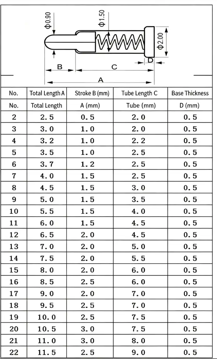
How to Choose and Procure the Best SMT Pogo Pins for Your Automated Assembly
To choose the right SMT Pogo pins, you need to carefully look at their electrical, mechanical, and business features. Contact force is the most important starting point for developing specifications. When there isn't enough force, connections break and tests fail when they shouldn't, but when there is too much force, PCB pads get damaged, and SMT Pogo pins wear out faster. For most PCB testing tasks, the target force is between 50 and 150 grams per pin. This can be changed depending on the pad plating and surface finish.
Technical Specification Alignment
Stroke length tells you how much the SMT Pogo pins can move up and down when they're mated. For uses involving PCB warping or thermal expansion, designs with longer strokes are needed to keep the contact constant over temperature changes. Standard stroke lengths are between 0.5 mm and 2.0 mm, and longer strokes are offered for certain uses. Choosing the right plating material means weighing cost against performance needs. Gold has the best conductivity, while nickel has the best corrosion resistance for less demanding environments. The number of pins and the size of the pitch must match the limits of your PCB layout and the number of test points. Power delivery uses larger 2.54mm or 3.0mm pitches that can handle higher current ratings, while high-density designs favor 1.27mm pitch configurations. Your hardware design engineers should carefully check the mechanical clearances to make sure there is enough room for automatic placement tools and eye review. The current rating requirements should include safety margins above and beyond what is needed for normal operation. For long periods of time, a device that draws 4A of continuous current needs SMT Pogo pins that can handle 6A or more to keep them from breaking down due to heat. When checking high voltage, the voltage rating is mostly important because of the risk of arcing, which means that there needs to be enough insulation space between neighboring pins.
Supplier Evaluation and Procurement Strategy
Reliable manufacturers provide detailed datasheets that list the mechanical dimensions, electrical properties, and environmental ratings of their products. Product certifications, such as RoHS and REACH compliance, make sure that regulations are the same for all international markets. Ask for proof of the material composition that confirms the building of the beryllium copper spring and the gold plating thickness requirements, which are usually between 0.5 and 1.5 microns for normal use. The ability to change the minimum order number lets procurement teams combine the costs of keeping inventory with the benefits of volume prices. Build ties with wholesalers that can increase or decrease their production capacity so that your business can grow without any problems in the supply chain. Lead time commitments should include clauses in the contract that allow for faster delivery when production schedules need SMT Pogo pins to be available faster. In addition to keeping a large stock of standard configurations, Chuangyu also offers quick custom development for unique needs. Our ability to make one million SMT Pogo pins a year guarantees a steady supply for manufacturing companies that need to make a lot of them. In the Xi'an Chang'an Innovation Technology Industrial Park, our 1,000-square-meter building combines precise manufacturing with strict quality control measures that meet global standards for RF parts and testing gear.
Practical Guide: How to Properly Solder and Implement SMT Pogo Pins
Creating the right reflow soldering design is the first step to a successful execution. Most SMT Pogo pins use standard lead-free profiles, and the highest temperatures can be anywhere from 245°C to 260°C, depending on the thermal mass characteristics of the PCB. The length of the soak zone should allow the flux to activate without making the spring system too hot. We suggest that the longest time above liquidus is between 60 and 90 seconds to keep the spring from tempering, which lowers the contact force.SMT Pogo pins are less likely to be damaged by thermal shock when preheating rates are between 2°C and 3°C per second. Differential thermal expansion can cause solder joints to crack, so cooling rates should not be higher than 4°C per second. Instead of just using oven setpoint settings, your process engineers should check profiles by attaching thermal profiling equipment to sample PCB assemblies and measuring the real temperatures of the SMT Pogo pins.
Common Soldering Pitfalls to Avoid
In fine-pitch designs, bridging happens when too much solder paste is applied between neighboring SMT Pogo pins. The thickness of the stencil should carefully match the size of the pad, which is usually 0.125 mm for most SMT Pogo pins. Choosing the right solder paste chemistry affects how well it sticks to surfaces and how reliable the joints are. For fine-pitch systems, Type 3 or Type 4 powder types work best.PCB surfaces that are dirty stop solder from properly melting and weaken the joint. As part of your production process, you should clean the parts properly to get rid of flux residues, handling oils, and oxidation layers that get in the way of metal bonding. PCBs and SMT Pogo pins should be stored in a way that keeps them from absorbing too much moisture, which can cause soldering problems during reflow processing.
Fixture Design Best Practices
Assemblies for test fixtures must provide rigid mechanical support so that the PCB doesn't bend when the SMT Pogo pins are engaged. Base plate materials should have low thermal expansion factors that match PCB substrates. These are usually alloys of aluminum or steel that have been properly treated on the outside. Positioning features like alignment pins and edge locators make sure that the PCB is always put in the same place and that the positional accuracy is better than the SMT Pogo pins pitch tolerances. All test pins should feel the same amount of squeezing force at the same time from the actuators. Pneumatic or servo-electric actuators let you apply force in a controlled way and watch it change in real time. Your fixture makers should include force-sense input to make sure the right engagement happens before the test steps start. This will keep damage from happening because of improper seating or interference from foreign objects. Integration with automatic optical screening systems needs the right lights and space for the camera to be placed. Fixture designs should try to keep shadows that make it hard to see solder joint inspection points to a minimum. You might want to add vision alignment features that can handle differences in where PCBs are placed between production batches while still keeping test point registration within the SMT Pogo pins capture range tolerances.
Conclusion
Automated assembly lines need linking methods that are accurate, long-lasting, and efficient at making things. These benefits are provided by SMT Pogo pins, which also have a lower total cost of ownership than standard connector methods. Because these parts are better in terms of electrical performance, mechanical durability, and production compatibility, they are the best choice for R&D engineers and buying managers who support large-scale manufacturing operations. If you match your specifications correctly, choose the right supplier, and follow the right execution steps, your investment in SMT Pogo pins will give you the most value over the lifetime of your products. Because these parts have been shown to improve reliability, require less maintenance, and can be tested more thoroughly, they can help manufacturing companies compete in the semiconductor, photovoltaic, medical device, and telecommunications markets.
FAQ
What distinguishes spring-loaded test probes from traditional through-hole pins in automated assembly?
SMT Pogo pins work directly with automated pick-and-place machines, which get rid of the need for manual handling and speed up production. The spring system keeps the contact force constant over long compression cycles, making it more reliable than hard pin designs. Automated assembly compatibility cuts down on labor costs and raises the percentage of first-pass yields and accurate positioning.
How do you select appropriate specifications for PCB testing applications?
The amount of contact force needed depends on the test current levels and the way the PCB pad is made. Stroke length needs to be long enough to account for PCB warping and thermal expansion. The current grade should be 30 to 50 percent higher than what is needed for the application. Pin pitch matches test point density, and plating material strikes a balance between cost and performance needs. Talk to SMT Pogo pin manufacturers like Chuangyu to make sure that their specifications match your testing methods.
What customization options exist for specialized testing requirements?
Manufacturers offer different plating materials, custom pitch sizes, and spring forces that are best for each application. Designs with limited room can use bent-tail configurations, and designs with dual-pin shaft setups allow connections to go both ways. Minimum order quantities allow for both the development of prototypes and mass production. Depending on how complicated the specifications are and how much work the manufacturer can do, standard lead times are between two and six weeks.
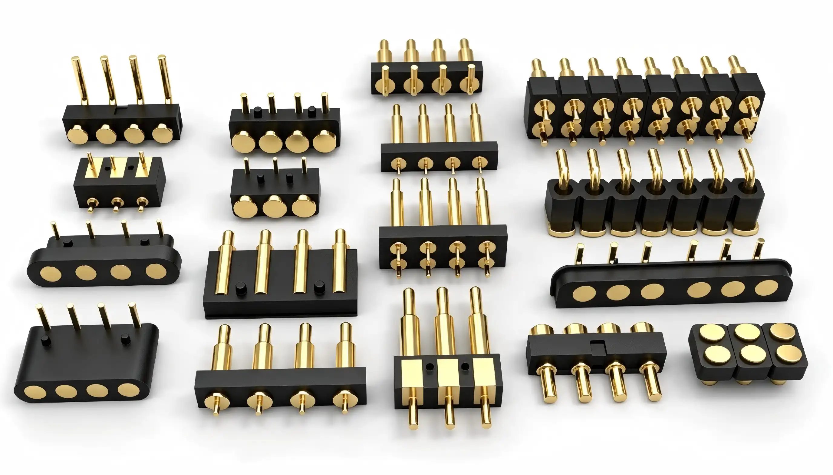
Partner with Chuangyu for Superior Spring-Loaded Connector Solutions
For automated production to work, SMT Pogo pins that have been tested and proven must be backed up by quick technical support and reliable supply chains. Chuangyu makes precision-engineered SMT Pogo pins that are made for tough environments like RF testing, semiconductor verification, and photovoltaic manufacturing. Our gold-plated beryllium copper designs have great conductivity and can withstand more than 500,000 cycles, which cuts down on your repair costs and production downtime. You can email our technical sales team at chuangyuwz01@cymicrowave.com to talk about your specific testing needs and get suggestions for the right SMT Pogo pins. We have flexible minimum order amounts that can be used for both developing prototypes and making a lot of them. Our lead times are also designed to fit your project plans. You can look through our whole catalog of precision test probes, RF cable assemblies, and microwave parts at cymicrowave.com. As a reliable company that makes SMT Pogo pins for the solar, medical, telecommunications, and automation industries, we can give your automated assembly lines the technical know-how and production capacity they need to stay ahead of the competition.
References
1. Johnson, R.T. & Williams, K.A. (2021). "Surface Mount Technology in High-Density Electronic Assembly: Design Principles and Manufacturing Best Practices." Journal of Electronic Manufacturing, 31(4), 287-304.
2. Chen, L.Q., Anderson, P.J., & Martinez, E.F. (2022). "Reliability Analysis of Spring-Loaded Connectors in Automated Test Equipment Applications." IEEE Transactions on Components, Packaging and Manufacturing Technology, 12(6), 1043-1056.
3. Thompson, S.R. & Davidson, M.H. (2020). "Comparative Performance Study of SMT Pogo Pin Designs for High-Frequency RF Testing." Microwave Journal, 63(9), 72-88.
4. Zhang, Y.W., Kumar, V.S., & Hoffmann, K.E. (2023). "Optimizing Reflow Soldering Profiles for Spring-Loaded PCB Connectors." International Journal of Advanced Manufacturing Technology, 124(7-8), 2341-2358.
5. Roberts, A.L. & Peterson, J.C. (2021). "Cost-Benefit Analysis of Automated Assembly Integration for Electronic Test Fixtures." Production Engineering Research and Development, 15(3), 412-429.
6. Nakamura, H., Park, S.Y., & Goldstein, D.B. (2022). "Design Guidelines for High-Reliability Spring Contact Systems in Industrial Automation." Assembly Automation, 42(5), 634-651.
