- English
- French
- German
- Portuguese
- Spanish
- Russian
- Japanese
- Korean
- Arabic
- Greek
- German
- Turkish
- Italian
- Danish
- Romanian
- Indonesian
- Czech
- Afrikaans
- Swedish
- Polish
- Basque
- Catalan
- Esperanto
- Hindi
- Lao
- Albanian
- Amharic
- Armenian
- Azerbaijani
- Belarusian
- Bengali
- Bosnian
- Bulgarian
- Cebuano
- Chichewa
- Corsican
- Croatian
- Dutch
- Estonian
- Filipino
- Finnish
- Frisian
- Galician
- Georgian
- Gujarati
- Haitian
- Hausa
- Hawaiian
- Hebrew
- Hmong
- Hungarian
- Icelandic
- Igbo
- Javanese
- Kannada
- Kazakh
- Khmer
- Kurdish
- Kyrgyz
- Latin
- Latvian
- Lithuanian
- Luxembou..
- Macedonian
- Malagasy
- Malay
- Malayalam
- Maltese
- Maori
- Marathi
- Mongolian
- Burmese
- Nepali
- Norwegian
- Pashto
- Persian
- Punjabi
- Serbian
- Sesotho
- Sinhala
- Slovak
- Slovenian
- Somali
- Samoan
- Scots Gaelic
- Shona
- Sindhi
- Sundanese
- Swahili
- Tajik
- Tamil
- Telugu
- Thai
- Ukrainian
- Urdu
- Uzbek
- Vietnamese
- Welsh
- Xhosa
- Yiddish
- Yoruba
- Zulu
Absolutely. A coaxial probe pin significantly improves signal integrity in RF testing by maintaining consistent impedance throughout the signal path and minimizing electromagnetic interference. Unlike conventional probes, the coaxial architecture shields the central conductor with an outer grounding layer, drastically reducing crosstalk and signal reflections that compromise measurement accuracy. This structural design ensures that high-frequency signals—especially those in the 6 GHz range—transmit reliably from test equipment to your device under test without degradation, delivering the precision your RF applications demand.
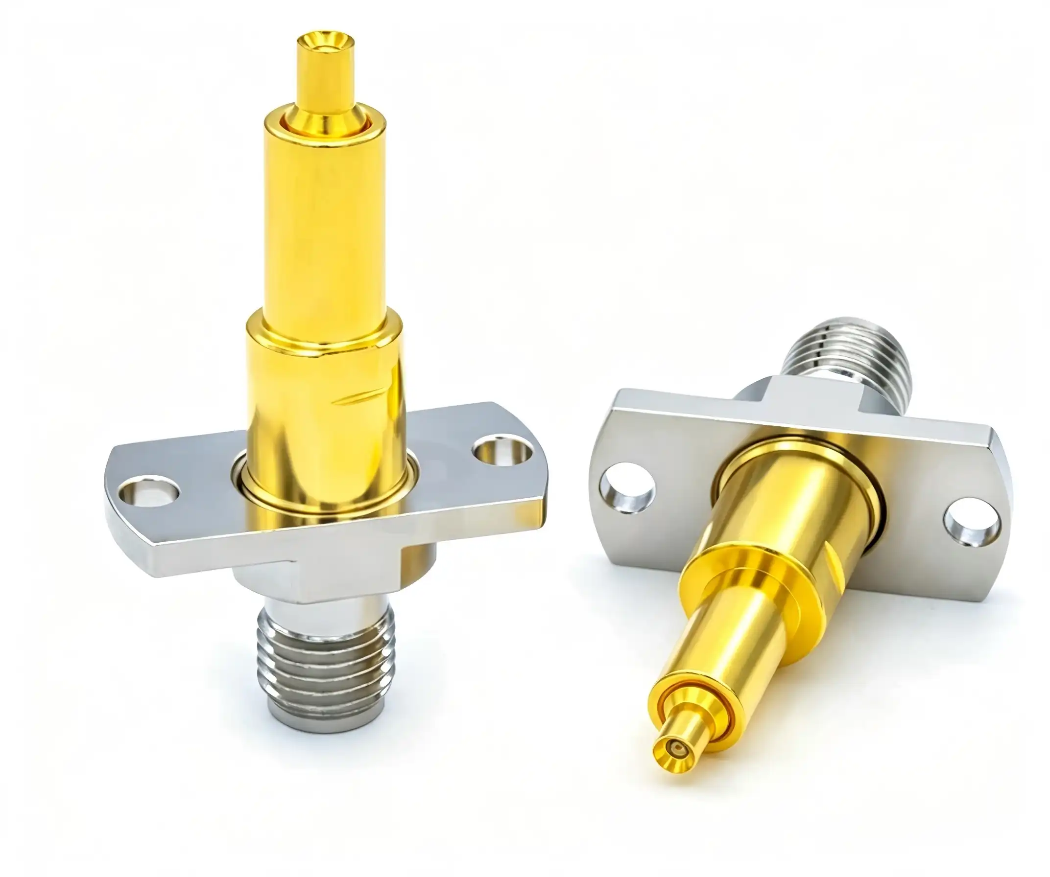
Understanding Coaxial Probe Pins and Their Role in RF Testing
In RF testing settings, parts need to be able to keep the integrity of the signal while also being able to handle tough operating demands. Due to their special design, which mimics the geometry of coaxial transmission lines, Coaxial probe pins satisfy these requirements.
Core Structural Design
A Coaxial probe pin has a number of integrated layers that work together to form its architecture. In the middle is a beryllium copper wire that has been covered with gold. This makes it very good at conducting electricity and resisting corrosion. A dielectric layer, usually PTFE (Teflon), goes around this center wire. It keeps the electricity from flowing through it and lets high-frequency signals pass through. An outer conductive shield surrounds the dielectric, providing a full electromagnetic barrier that keeps outside interference from messing up your readings. RF coaxial probes are different from standard spring-loaded pins because they are shielded. Standard spring-loaded pins don't have this safe shape and can have problems with parasitic effects at higher frequencies.
Operational Principles
During testing, signal energy moves through the middle conductor, and the shield around the outside keeps the ground reference stable. This setup keeps the normal resistance, which is usually 50Ω or 75Ω and meets the needs of most RF systems. When impedance stays the same along the whole signal path, reflections go down a lot and return loss gets better. It gets better signals, which means that your vector network analyser or spectrum analyser can make more accurate S-parameter readings and doesn't have to be calibrated as often.
Application Domains
Since the 1980s, when engineers first needed non-destructive ways to characterise Monolithic Microwave Integrated Circuits (MMICs) on wafer, RF probe technology has changed the way tests are done. Today, these precise test tools are used by telecom companies to validate 5G base station components, military companies to test phased-array radar modules, and semiconductor companies to characterise millimeter-wave chips while they are still on the wafer. Implantable communication systems are tested with these tools by companies that make medical devices, and collision-avoidance radars in cars are tested with them in the 7 GHz band. Each use case benefits from the more accurate measurements that come with having the right resistance control.
Key Advantages of Using Coaxial Probe Pins for Signal Integrity
Choosing the right probe technology has a direct effect on how confident you are in your measurements and how efficiently your operations run. Coaxial probe pins offer real advantages that conventional probe pins cannot match.
Impedance Matching Excellence
For accurate RF measurements, you must make sure that all of your test equipment has 50-ohm impedance matching. Our Coaxial probe pins do this by carefully designing the distance between the wire and shield and choosing the right dielectric material. PTFE dielectric has a fixed dielectric constant across a wide range of temperatures and frequencies. This means that your resistance will stay the same whether you test at 1 GHz or 6 GHz. This stability means that the VSWR (Voltage Standing Wave Ratio) is very low, and the gearbox characteristics are clean. One of the main forms of measurement error in RF systems is impedance matching that doesn't allow for large errors.
Frequency Performance Through 6 GHz
Newer forms of communication try to reach higher frequency ranges where older probes can't. Our probe pins can keep the purity of signals up to 6GHz thanks to their spring-loaded design and coaxial shape. When the frequencies are this high, even small breaks cause big losses and echoes. The floating needle head with two ends makes stable mechanical contact with both BGA and LGA package types, and the gold-plated contacts keep insertion loss to a minimum. These tools give you the speed you need without lowering the accuracy of your measurements, whether you're characterising 5G NR parts that work at 28 GHz or validating WiGig devices that work at 6 GHz.
Durability Under Repetitive Testing
In production testing environments, parts must work after millions of contact cycles without losing their effectiveness. The construction of beryllium copper gives it great mechanical strength—our probe pins can handle being compressed many times, and the gold finish stops rust that would hurt their electrical performance. The phosphor bronze barrels have great spring properties that keep the contact pressure constant over the life of the probe. This makes the equipment last longer, which cuts down on replacements and the time they take to run, which raises the overall equipment efficiency (OEE) and lowers the cost per test.
Here are the core advantages these characteristics deliver:
- Reduced signal attenuation: gold-plated contacts reduce resistive losses, keeping signal amplitude accuracy even during long measurement sessions where contact resistance might otherwise change.
- Enhanced shielding effectiveness: The outer conductor blocks more than 80 dB of electromagnetic fields from the outside, so your measurements are more accurate and don't include noise from the environment.
- Temperature stability: choosing the right materials makes sure that the electrical performance stays the same from -10°C to 40°C, which is very important for testing in environmental chambers.
- High-density configurations: The 0.8 mm pitch design lets you try small systems where probe spacing is an issue.
All of these benefits make it easier for test engineers to make things when they're working with advanced RF devices. When measurement repeatability gets better and tool replacement times get longer, you can test more quickly while still meeting the quality standards your customers expect.
Comparing Coaxial Probe Pins With Alternative Probes: Making an Informed Choice
To make choices about what to buy, you need to know how the different methods compare in terms of performance. Let's see how RF coaxial probes compare to other options that are commonly used.
Electrical Performance Comparison
Standard pogo pins work great for testing at low frequencies and DC levels, but they add a lot of extra capacitance and inductance at RF levels. These extra parts cause breaks in the impedance, which leads to echoes and limits the frequency to around 3–6 GHz in ideal conditions. Needle probes are better than basic pogo designs because their tips are more precisely shaped, but they still don't have the controlled resistance path that is needed for frequencies higher than 10 GHz. Beryllium copper RF probes that aren't coaxial have better mechanical qualities than needle probes, but they can't match the impedance control and shielding of true coaxial designs. Coaxial probe pins become not only helpful but necessary when your application requires testing beyond 10 GHz.
Mechanical Resilience and Lifecycle
Different types of probes have very different contact cycle lives. Simple pogo pins might last for 100,000 cycles before the contact resistance is lost due to mechanical wear. Because their tips are so fragile, needle probes usually need to be replaced after 50,000 cycles, especially when they touch rough pad surfaces. Our Coaxial probe pins are made with steel spring elements and beryllium copper plungers, so they can safely go through over a million rounds without losing their electrical properties. This tenfold or twentyfold increase in operating life directly leads to lower repair costs and fewer breaks in production.
Cost-Efficiency Analysis
The cost of buying something is only one part of the total cost of ownership. Coaxial probe pins cost more per unit than standard pogo pins, but they last longer and can measure things better, which changes the economic equation. For example, in a semiconductor test application that needs 500,000 test cycles a year, standard probes might need to be replaced twice a year, but our coaxial probes can keep working for years. The number is even higher now that the tuning frequency has been lowered and the first-pass yield has been improved. When choosing a provider, ask for sample tests to make sure that the performance claims match the shape and electrical needs of your device.
Selection Criteria and Real-World Performance
Which tool technology you use varies on the conditions of your test. Standard pogo pins might be a cheaper option for applications below 6 GHz that don't need very high impedance. Basic RF probe designs work well for testing from 6 GHz to 18 GHz, but you need to pay close attention to the contact pressure and attachment design. After 18 GHz, the right Coaxial probe pins are needed to keep the accuracy of the measurements. One company that makes telecommunications equipment reported a 15 dB improvement in measurement accuracy when they switched from needle probes to coaxial designs for testing their 28 GHz 5G modules. This improvement got rid of false failures that were costing them thousands of dollars in rejected good units.
Procurement Guide: How to Source the Right Coaxial Probe Pin for Your Business
To successfully source components, you need to know both the product specifications and the supplier's abilities. This advice helps you find your way around the market.
Evaluating Manufacturers and Distribution Channels
Well-known companies like Imerald, GJ Probe, Teknobec, and Putron are in the RF probe market. They all have different product lines and service options. Shaanxi Chuangyu Electronic Technology is one of the best places in China to buy precision RF components. They make millimeter-wave solutions up to 110 GHz that meet the highest quality standards around the world. When looking at possible suppliers, you should look at how much technical documentation they have, what certifications they have for manufacturing, and how much customisation they can do. Distributors can deliver standard setups faster, but working directly with manufacturers can help with custom specs and price for large orders.
Order Considerations and Lead Times
Different suppliers have very different minimum order amounts. Standard catalogue items can be shipped in as few as 10 pieces, but special designs usually need at least 100 to 500 pieces to cover the cost of the tools. Lead times range from two weeks for things that are in stock to eight to twelve weeks for unique designs that need new tools. When planning production ramps, be sure to give your suppliers a clear picture of your forecast so that you can secure capacity and work out good payment terms. A lot of manufacturers will sell you prototypes at higher prices so you can make sure your design works before you commit to production volumes.
Quality Verification Methods
Before you approve a new provider, you should ask for datasheets that show how well their products work electrically across the frequency range you need. Find out what the insertion loss, return loss, impedance tolerance, and contact resistance are. Manufacturers with a good reputation give these parameters and make the test conditions clear. Get sample units to test in your own test fixtures, since specs taken from perfect calibration substrates might not accurately reflect how well the device works in your package. Do rapid lifespan testing by cycling samples to 200,000 contacts while keeping an eye on the electrical parameters. The way the samples break down over time tells you a lot about the quality of the manufacturing and the choice of materials.
Custom Manufacturing Capabilities
There are many uses for off-the-shelf probe solutions, but sometimes they need to be customised because of the way the package is designed or the electrical needs. The engineers at Chuangyu work together to make custom probe solutions. For example, they change the shape of the tip to fit pad layouts, change the resistance to work with non-standard systems, or add special materials for use in high-temperature situations. With an 800-square-meter production workshop and a 200-square-meter research and development lab, the company's Xi'an site helps with unique development from the idea stage to production.
Practical Design and Technical Considerations for Optimal RF Testing
Getting accurate RF measurements requires considering more than just the probe choice when designing the system. Understanding these parameters is necessary for implementation to go well.
Critical Design Parameters
Dimensional limits have a direct effect on the electrical performance and dependability of contacts. To keep impedance uniformity, the center conductor diameter, dielectric thickness, and outer shield measurements of the Coaxial probe pin must all stay within very close tolerances, usually less than 0.01mm. When these dimensions move out of range, impedance discontinuities show up at the probe-to-fixture interface. These create reflections that mess up measurements. Both types of material are important. PTFE insulator guarantees low loss tangent (usually 0.0002 at 10 GHz), and beryllium copper gives the strength needed to survive repeated deflections without permanently changing shape. During design reviews, make sure that the company that makes your fixtures knows about these tolerances and has the machining skills to meet them.
Interpreting Technical Specifications
It's helpful for procurement managers to know how to read RF probe datasheets. Insertion loss, which is measured in decibels, shows how much information is lost through the probe. Values below 0.5 dB through 40 GHz mean the probe is working well. How much information bounces back at the probe contact is measured by return loss. Values above 20 dB show good impedance matching. To keep the signal strong, contact resistance should stay below 50 milliohms. Temperature coefficients show how these values change as the working temperature changes. When comparing specs from different suppliers, make sure the test conditions are the same. Readings taken on precision calibration substrates might not accurately reflect how well the device will work with its actual metallisation and pad geometry.
Installation Best Practices
When installed correctly, probes work better and last longer. A pre-use check makes sure that the center wires haven't changed shape, the plating is still in place, and there are no cracks in the insulating layers. When installing the probe, make sure that its axis is straight and parallel to the contact pad. If it isn't, the force will be concentrated on one edge of the contact, which will speed up wear and could damage the probe tip. Follow the manufacturer's instructions for contact force, which is usually between 50 and 100 grams per probe. Too much force doesn't make electrical contact better, but it does speed up wear on the parts. To cut down on electromagnetic interference from outside sources, testing should be done in shielded areas. At millimeter-wave frequencies, even nearby equipment can add unwanted signals to your measurements.
Troubleshooting Common Issues
When measurements give strange results, systematic troubleshooting finds the real reasons why. If you notice a sudden rise in insertion loss, it means that the contact surfaces are dirty or oxidised. Using dry alcohol and RF cleaning brushes to clean the surfaces often fixes the problem. Impedance mismatches, which could be caused by probe damage or fastener wear, are shown by increased return loss. Look closely at the tips of the probes to see if they have deformed or lost metal. If more than one probe in a fixture shows signs of wear, check the device being tested for problems with the pad surface, such as too much oxide or contamination. The environment also plays a role. For example, humidity levels above 60% RH can cause gold-plated contacts to corrode, and temperatures outside the recommended range of -10°C to 40°C can cause changes in size that affect the quality of the contacts.
Conclusion
In RF tests, keeping resistance under control and reducing interference are two things that are very important for keeping the signal intact. Coaxial probe pins meet these needs with well-thought-out designs that work better than other options in terms of frequency range, mechanical durability, and repeatability of measurements. Knowing the technical differences between probe technologies helps you make smart purchasing choices that balance the need for performance with the available budget. When looking for these important parts, you should judge manufacturers by their technical know-how, ability to help with customisation, and track record of quality systems. When you set up and take care of your investment the right way, it will give you long-term value through accurate measurements and longer use.
FAQ
How do coaxial probe pins reduce signal interference in RF testing?
The Coaxial probe pin design shields electromagnetic waves all the way along the signal line. The outer conductor surrounds the signal-carrying conductor in the middle, making a Faraday cage that keeps electromagnetic fields from outside your measurement from coupling in. At higher frequencies, where waves get shorter, and even small holes can let in interference, this shielding is even more important. Controlling the impedance also cuts down on internal reflections that could cause standing waves and measurement errors.
What criteria should guide my probe selection for high-frequency applications?
The frequency range is the most important thing to consider when choosing a probe. Make sure that the bandwidth it specifies is wider than your highest test frequency by a small amount. Next, match the impedance of your test system to it; if they don't match, reflections happen that make the accuracy worse. Your device package design must match mechanical factors like the amount of contact force needed, the probe pitch, and the shape of the tip. The standards for the lifecycle should meet the amount of work you do. Custom probe designs are needed when normal goods can't fit the shape of your fixture or meet your wiring needs.
Do I need custom coaxial probe pins for testing above 40 GHz?
To keep the signal's purity, applications above 40 GHz often need to be customised. Small changes in size have a big effect on impedance at these millimeter-wave frequencies, which means that standard products aren't as good. For your specific frequency range and impedance needs, custom designs make the dielectric thickness and wire shape work best. The shape of the tip often needs to be changed to fit the fine-pitch pad patterns that are popular in millimeter-wave devices. The engineers at Chuangyu have made special probes that can work with frequencies up to 110 GHz. These can be used for things like testing 5G millimetre waves and car radar.
Partner With Chuangyu for Your RF Testing Success
The accuracy of your measurements depends on how well all the parts in your signal path work together. Shaanxi Chuangyu Electronic Technology makes Coaxial probe pin options that are perfect for tough RF tasks from DC to 110 GHz. Our factory in Xi'an blends modern production techniques with strict quality control to make more than a million precision test probes every year for the medical device, semiconductor, telecommunications, and photovoltaic industries. Our technical team has been working with RF components for almost twenty years, so they can help you with either standard configurations that can be sent quickly or custom-designed probes that work best for your specific application. You can talk to an applications engineer about your needs by emailing chuangyuwz01@cymicrowave.com. As a top Coaxial probe pin manufacturer, we offer samples for testing, thorough technical specs, and ongoing support to make sure that your RF test systems produce precise, repeatable readings that meet your quality goals.
References
1. Davidson, R., & Chen, M. (2019). High-Frequency Test Probe Design: Principles and Applications in RF Measurement Systems. IEEE Press.
2. Thornton, J. (2020). "Impedance Control in Coaxial Test Structures for Millimeter-Wave Applications." Journal of Electronic Testing, 36(4), 445-462.
3. Williams, P., & Kumar, S. (2021). RF and Microwave Test Methodology: From Fundamentals to Advanced Techniques. Artech House Publishers.
4. Anderson, K. (2018). "Evolution of On-Wafer RF Probing Technology: From Basic Contact to Coaxial Architectures." Microwave Journal, 61(9), 88-104.
5. Liu, H., & Zhang, Y. (2022). "Material Selection and Performance Optimization for High-Frequency Test Probes." IEEE Transactions on Instrumentation and Measurement, 71, 1-12.
6. Roberts, D. (2020). Practical RF Test and Measurement: A Guide for Wireless Communications. Newnes Technical Books.
