- English
- French
- German
- Portuguese
- Spanish
- Russian
- Japanese
- Korean
- Arabic
- Greek
- German
- Turkish
- Italian
- Danish
- Romanian
- Indonesian
- Czech
- Afrikaans
- Swedish
- Polish
- Basque
- Catalan
- Esperanto
- Hindi
- Lao
- Albanian
- Amharic
- Armenian
- Azerbaijani
- Belarusian
- Bengali
- Bosnian
- Bulgarian
- Cebuano
- Chichewa
- Corsican
- Croatian
- Dutch
- Estonian
- Filipino
- Finnish
- Frisian
- Galician
- Georgian
- Gujarati
- Haitian
- Hausa
- Hawaiian
- Hebrew
- Hmong
- Hungarian
- Icelandic
- Igbo
- Javanese
- Kannada
- Kazakh
- Khmer
- Kurdish
- Kyrgyz
- Latin
- Latvian
- Lithuanian
- Luxembou..
- Macedonian
- Malagasy
- Malay
- Malayalam
- Maltese
- Maori
- Marathi
- Mongolian
- Burmese
- Nepali
- Norwegian
- Pashto
- Persian
- Punjabi
- Serbian
- Sesotho
- Sinhala
- Slovak
- Slovenian
- Somali
- Samoan
- Scots Gaelic
- Shona
- Sindhi
- Sundanese
- Swahili
- Tajik
- Tamil
- Telugu
- Thai
- Ukrainian
- Urdu
- Uzbek
- Vietnamese
- Welsh
- Xhosa
- Yiddish
- Yoruba
- Zulu
knowledge
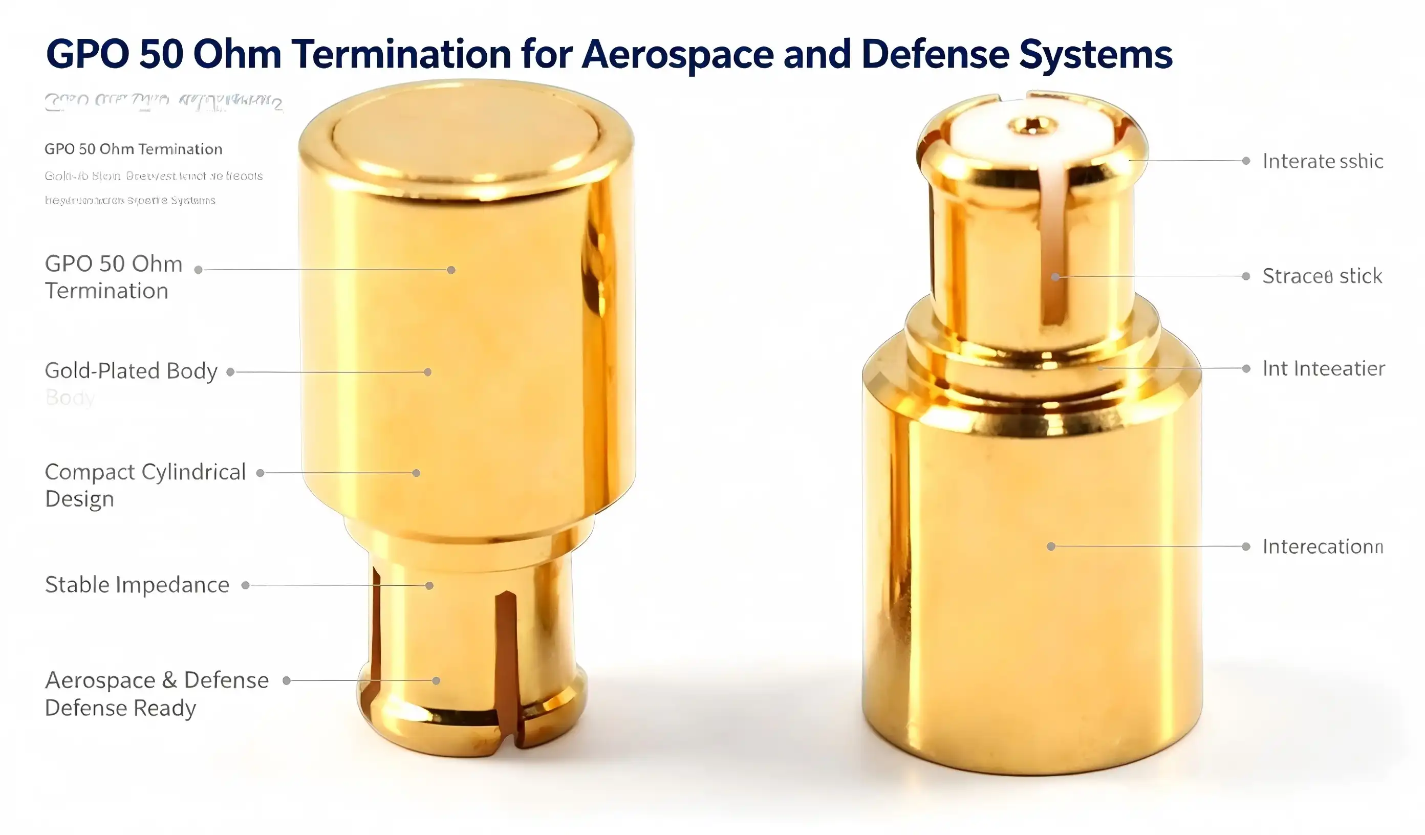
Correct and reliable termination components are required to absorb undesired signal energy and ensure correct impedance matching for high-frequency RF and microwave systems, including radar, satellite communication, and millimeter-wave test equipment. The GPO 50 Ohm Termination is constructed for rugged situations. It utilizes a tantalum nitride resistive element, gold-plated brass connection body, and PTFE insulation to provide consistent performance from DC to 40GHz. This article discusses the attributes that make a GPO 50 Ohm Termination ideal for aerospace and military applications, how it works under intense mechanical and environmental stress, and how good maintenance increases operating life. We always make reference to the technical parameters of the GPO 50 Ohm Termination product line produced by Shaanxi Chuangyu Electronic Technology Co., Ltd.

What Makes a GPO 50 Ohm Termination Suitable for High-Frequency Testing?
What Frequency Range Can a GPO 50 Ohm Termination Cover?
The GPO 50 Ohm Termination is intended to function reliably from DC to 40GHz, ideal for the rising bandwidth demands of contemporary radar, satellite communication, and 5G test equipment. The small metal package design with minimized parasitic reactance and uniform electrical properties throughout the whole band achieves broad frequency coverage. This wide frequency range is essential for engineers using vector network analyzers or millimeter-wave signal generators to calibrate test systems or to verify device performance, as a GPO 50 Ohm Termination must present a stable, predictable load impedance regardless of where in the spectrum the measurement takes place.
How Does VSWR Performance Affect a GPO 50 Ohm Termination?
The voltage standing wave ratio, or VSWR, is one of the most important performance parameters for any termination component, and the GPO 50 Ohm Termination is required to keep the VSWR at 1.4 or below across the whole working frequency range. A low VSWR means the terminal is absorbing incoming signal energy well and reflecting less of that energy back into the system. This is critical for proper calibration and measurement integrity in vector network analyzer applications. Any loss of VSWR performance, either by contamination, mechanical damage, or wear accumulated over a period of time, might produce measurement error in a whole test setup; thus, the recommendation of periodic VSWR verification is recommended as part of normal maintenance for a GPO 50 Ohm Termination in active operation.
What Role Does the Resistive Element Play in a GPO 50 Ohm Termination?
The core of a GPO 50 Ohm Termination is a resistive element consisting of a tantalum nitride resistive layer linked to a high thermal conductivity ceramic base. This combination is particularly chosen to release absorbed RF energy as heat without impairing electrical performance. The resistive layer sets the exact 50 ohm impedance that the termination is supposed to provide, while the ceramic substrate effectively draws heat away from the resistive film to avoid localized hot spots during continuous power absorption. The quality and uniformity of this resistive element directly dictate how accurately a GPO 50 Ohm Termination maintains its rated impedance and power handling capability throughout its operational lifetime.
How Reliable Is a GPO 50 Ohm Termination in Military and Space Environments?
What Temperature Range Can a GPO 50 Ohm Termination Withstand?
Aerospace and military applications sometimes subject RF components to extremes of temperature, and a GPO 50 Ohm Termination is rated for continuous performance across a broad -55°C to +125°C range. The power handling capability is derated at the higher end of this range to 0.2W at 125°C (compared with the full 2W rating at 25°C), reflecting the real temperature constraints of the resistive element and packaging materials. This large operational temperature range makes a GPO 50 Ohm Termination ideal for high-altitude aviation systems, satellite payloads, and outdoor radar installations where ambient conditions may vary widely between severe cold and strong heat within a single mission profile.
How Many Insertion Cycles Does a GPO 50 Ohm Termination Support?
Mechanical durability is required for components used in test environments or field-deployable systems where frequent connection and disconnection is required. A GPO 50 Ohm Termination is constructed with a brass body that is rated for at least 500 insertion and extraction cycles without significant degradation in electrical performance. This mechanical strength is due to the tight manufacturing tolerances of the SMP male connection interface and the gold plating resistant to wear over several mating cycles. This cycle rating enables labs and test facilities using a GPO 50 Ohm Termination as a calibration load across several daily measurements to have the assurance that the component will continue to work consistently over a long service time before a replacement is required.
Why Does Push-In Connection Matter for a GPO 50 Ohm Termination?
A GPO 50 Ohm Termination utilizes a push-in connection technique that enables tool-free installation while preserving coaxial alignment between matching components. Threaded coaxial connections need precise torque management. This design greatly lowers the possibility of connection damage caused by over-torquing or misalignment, which is a major failure mechanism for threaded interfaces in high-density interconnect applications. Proper installation still demands that the connection be coaxially oriented at insertion and not forced twisting, which may distort the inner wire. The push-in architecture of the GPO 50 Ohm Termination allows the termination to be assembled in space-restricted modules for high-density RF subsystems in radar and satellite communication equipment where many connections need to be established fast and reliably.

How Should You Maintain and Store a GPO 50 Ohm Termination?
What Cleaning Steps Extend the Life of a GPO 50 Ohm Termination?
Maintaining consistent electrical performance in a GPO 50 Ohm Termination requires periodic cleaning of the connector interface, particularly after repeated insertion cycles introduce contamination or surface oxidation. Manufacturer guidance recommends cleaning the connector end face with an isopropyl alcohol swab after every 20 insertions and extractions, focusing specifically on any oxidized areas of the gold-plated layer that could otherwise degrade contact resistance and VSWR performance. Metal tools should never be used to scrape the insulating medium interface, since this can permanently damage the PTFE dielectric material. Following this cleaning protocol helps a GPO 50 Ohm Termination maintain its rated performance specifications across its full service life in demanding test and field environments.
How Should a GPO 50 Ohm Termination Be Stored When Not in Use?
Proper storage conditions play an important role in preserving the long-term performance of a GPO 50 Ohm Termination when it is not actively in service. Idle units should be stored in a dry environment between -20°C and +60°C with relative humidity at or below 50%, protecting the resistive element and connector plating from moisture-related degradation. In environments with humidity exceeding 60%, a dust cap should be installed on the connector interface to prevent moisture and corrosive gases from entering and compromising the connection quality. Facilities managing inventories of test components should also perform a monthly VSWR pre-test on stored units, returning any GPO 50 Ohm Termination exceeding a VSWR of 1.4 to the factory for calibration.
When Should a GPO 50 Ohm Termination Be Retested or Recalibrated?
In addition to normal cleaning and storage procedures, a GPO 50 Ohm Termination should be tested periodically to verify it is still performing to its rated spec after lengthy periods of usage. The manufacturer recommends full-range VSWR and power capacity testing with a network analyzer after accumulated working time exceeds 1500 hours or immediately following any incident of severe mechanical shock that could have affected the internal resistive element or the connector alignment. This approach to proactive testing is useful to detect performance drift prior to calibration accuracy or test measurement integrity being impacted. This is especially relevant to aerospace and defense applications where a GPO 50 Ohm Termination can be used as a reference load in critical system verification procedures.

Conclusion
A GPO 50 Ohm Termination delivers dependable broadband performance, mechanical durability, and thermal resilience suited to the demanding conditions of aerospace, defense, and millimeter-wave test applications. Shaanxi Chuangyu Electronic Technology Co., Ltd., operating an integrated production, R&D, and testing base in Xi'an since 2022, manufactures RF components including coaxial terminations at scale for defense, telecommunications, and high-end electronics clients. With proven process standards and nearly two decades of industry expertise, the company supports engineers seeking reliable termination solutions. For technical datasheets or a customized quote, contact postmaster@cymicrowave.com today.
FAQ
Q1: What frequency range does a GPO 50 Ohm Termination cover?
A: It operates from DC up to 40GHz with a VSWR of 1.4 or lower.
Q2: What is the maximum power rating?
A: 2W at 25°C, derated to 0.2W at 125°C, with an instantaneous peak of 200W.
Q3: How many insertion cycles can the connector withstand?
A: The brass body supports at least 500 insertion and extraction cycles.
Q4: How often should the connector be cleaned?
A: Every 20 insertions, using an isopropyl alcohol swab on the gold-plated end face.
Q5: When should performance be retested?
A: After 1500 accumulated working hours or following any severe mechanical shock.
References
1. Pozar, David M. Microwave Engineering. John Wiley & Sons.
2. Institute of Electrical and Electronics Engineers (IEEE). IEEE Standard for Precision Coaxial Connectors.
3. Collin, Robert E. Foundations for Microwave Engineering. Wiley-IEEE Press.
4. Agilent Technologies (Keysight). Network Analyzer Basics.
5. International Electrotechnical Commission (IEC). IEC 61169: Radio-Frequency Connectors.
6. Maury Microwave. Microwave Connector Care and Handling Guide.
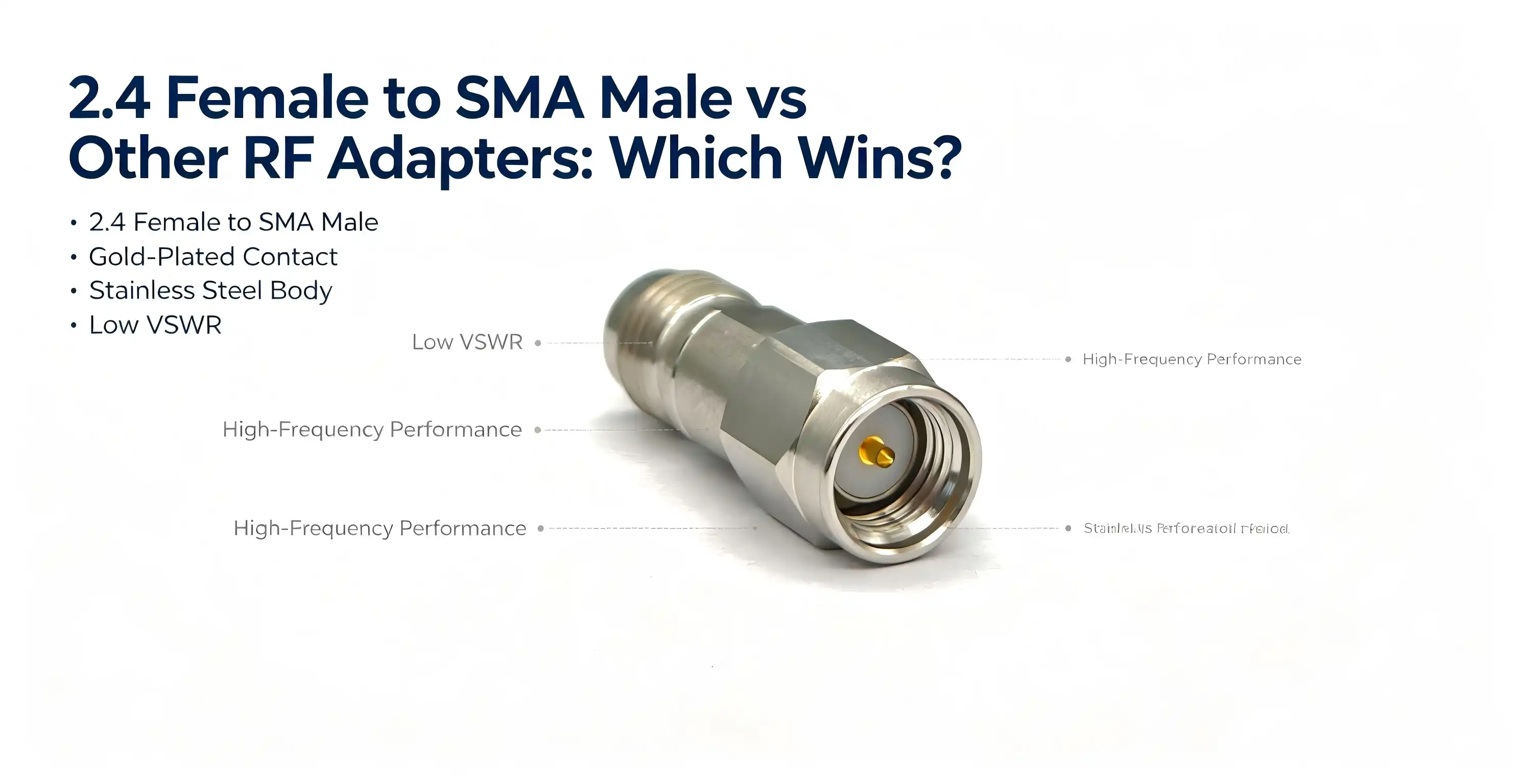
The coaxial adapter 2.4 female to SMA male has been found to be the most competent cross-series option for engineers needing to connect millimeter-wave instruments and microwave subsystems with interface mismatches. This adapter provides VSWR ≤1.35 from DC to 50 GHz, and connects precise 2.4mm ports on vector network analyzers to older equipment with SMA connectors, without compromising signal integrity. It offers improved high-frequency headroom and mechanical endurance compared to typical SMA-to-SMA, N-type, or RP-SMA options and is the ideal choice for 5G testing, semiconductor characterization, and radar system integration.

Understanding the 2.4 Female to SMA Male Adapter: Features and Specifications
Cross-Series Design and Material Engineering
The coaxial adapter 2.4 female to SMA male is a cross-series adaptation. At one end is a 2.4mm female connection with an internal pin receptacle, and at the other is an SMA male connector with an exposed center pin. This setup guarantees a stable interface conversion and signal relay from 2.4mm receiving ports to SMA transmitting terminals. Electrical performance is directly controlled by material choices. The exterior conductor is made of stainless steel, passivated to provide corrosion resistance and high mechanical strength. The inner conductor is gold-plated beryllium copper, which provides little contact resistance and allows low-loss transmission even at millimeter-wave frequencies. The insulating medium is PTFE (polytetrafluoroethylene). This dielectric substance has a low dissipation factor to provide constant 50Ω impedance matching across the whole working range.
High-Frequency Performance and Mechanical Reliability
The adapter covers DC to 50 GHz, so it will work with devices on the millimeter-wave and microwave frequency bands. VSWR remains <1.35 across the whole range of operation, and the insertion loss is clearly low. These are crucial metrics for calibrating sensitive instrumentation such as spectrum analyzers or network analyzers. The mechanical dependability is just as strict. The suggested torque for the connection is 0.5–0.8 Nm at both the 2.4 mm end and the SMA end. The ≥500 mating cycles plug/unplug life cycle rating is designed for rigorous repetition rates characteristic of high-frequency test benches. These requirements are consistent with MIL-STD-348 standards for connector interface, providing compatibility among multinational test environments.
Comparing 2.4 Female to SMA Male with Other Popular RF Adapters
Not all RF adapters are created equal. Understanding the differences minimizes expensive misapplication. Below is a straight comparison of the most common kinds of adapters in use, including the coaxial adapter 2.4 female to SMA male for specific RF connection requirements.
- Reverse Polarity SMA Female to 2.4mm Male: This is the reverse polarity of the SMA Female to 2.4mm Male. It is suitable for cases where the test instrument has a 2.4mm male port, and the item under test has a female SMA. The other one is. There isn't any universal interchangeability. You need one or the other depending on what the port is. ( Connector gender to port gender) .
- N-Type Adapters: N-type connections are designed for greater power levels and are physically bigger, making them perfect for base station feeder cables or outdoor RF equipment. Their frequency ceiling (often 18 GHz for precision grades) is much below the 50 GHz capacity of the 2.4mm-to-SMA interface; hence, N-type adapters are not good for mm-wave operations.
- RP-SMA Adapters: Reverse-polarity SMA adapters were developed for consumer wireless devices to comply with FCC rules on antenna modification. The reverse pin-out rules them out for use with conventional SMA or 2.4mm lab instruments, and so they are cast into the consumer Wi-Fi and WLAN devices.
- Weatherproof RF Adapters: Weatherproof adapters with an IP67 or higher grade provide additional protection against the elements when used outside. The cost premium is 20–40 % above ordinary grades, with a minimal extra insertion loss from sealing materials, suitable for field installations but unneeded in protected laboratory conditions.
Precision quality 2.4mm-to-SMA adapters from major manufacturers like Rosenberger, Huber+Suhner, and Chuangyu. Chuangyu’s solution meets international dimensional requirements and offers a reasonable per-unit price at volume. It’s a great fit for OEM manufacturing lines that need consistent quality at scale.
How to Choose the Right RF Adapter for Your Application
An incorrect choice of adaptor may waste engineering time and even distort measurement data. The decision framework has three axes: frequency range, environment, and life cycle cost. The frequency range is the immovable ground zero. For test systems over 26.5 GHz (the limit of normal SMA), you will need a 2.4 mm interface adaptor.
The coaxial adapter 2.4 female to SMA male provides usable bandwidth to 50 GHz, supporting all sub-6 GHz and mmWave 5G NR bands per 3GPP Release 17. If you only need to use microwave frequencies below 18 GHz, then an N-type or regular SMA-to-SMA adapter is all you need and is less expensive. Material and sealing needs depend on the environmental conditions. Passivated stainless steel and gold-plated beryllium copper provide accurate tolerances in indoor laboratory situations where sealed housings are not required.
For outdoor or high humidity applications, weatherproof versions should be specified, with a little performance penalty. Purchase price. Calculation of lifecycle cost must include mating cycles. For example, if the application requires 6 months of daily reconnections, then a $45 adapter certified for 500 cycles will beat a $20 option rated for 200 cycles. Always ask for and review the manufacturer’s technical datasheet before committing to big purchases.
Bulk Procurement and Supply Chain Considerations
Procurement managers procuring 2.4mm to SMA adapters at scale have unique issues in lead time, quality consistency, and specification compliance. A good distributor or manufacturer can demonstrate the depth of their stock and have a documented quality control system such as ISO 9001 certification, which will lessen the chances of your manufacturing line being stopped due to inferior components.
Custom adapter designs are available to OEM integrators whose equipment has non-standard port geometries or needs unique cable stubs. Working with a manufacturer with in-house RF design capabilities, such as Chuangyu, custom cross-series adapters may be designed to match dimensional and electrical specifications not accessible off-the-shelf.
Generally, volume price agreements result in substantial savings at 100 or more units. Asking for a first item inspection report and sample batch testing against stated VSWR and insertion loss criteria can safeguard the procurement team from receiving non-conforming inventory. Provide comprehensive traceability data to material certifications for the beryllium copper and stainless steel utilized in adapter fabrication.

Troubleshooting and Maintaining Your 2.4 Female to SMA Male Adapter
Pre-Use Inspection
Before each connection, visually examine the outer conductor for distortion. Also ensure that the gold plating on the center pin and pin receptacle is free of oxidation and pitting. Any physical damage to the 2.4 mm female pin hole or the SMA male pin of the coaxial adapter 2.4 female to SMA male should be replaced immediately. Damaged interfaces transmit measurement inaccuracy and risk destroying costly instrument ports.
Installation and Cleaning Protocols
Use a calibrated torque wrench at both the 2.4mm end and the SMA end set to 0.5-0.8 Nm. The main reasons for premature mechanical failure are oblique insertion or over-torquing. After use, interfaces should be cleaned with a specific RF cleaning brush moistened with Isopropyl alcohol to remove oxides and particle pollution. Store the adapter in a sealed and dry environment, at a temperature between -10℃ and 40℃ and relative humidity ≤60% RH.
Diagnosing Signal Anomalies
A rapid increase in standing wave ratio or an unanticipated spike in insertion loss indicates either a loose connection or internal conductor deterioration. Disconnect immediately, re-torque to specification, and re-measure. If the abnormality continues, retire the adapter. Continuing to use a deteriorating component affects all measurements downstream of the component and risks damage to the ports of your instruments, which will cost orders of magnitude more than the adapter itself.
Conclusion
The coaxial adapter 2.4 female to SMA male wins this comparison since no other comparable adapter type combines a 50 GHz operational ceiling, VSWR ≤1.35, and ≥500-cycle mechanical durability in a small cross-series structure. N-type adapters are rated for more power but only to 18 GHz. RP-SMA adapters are for consumer wireless only. Standard SMA-to-SMA adapters are good to 26.5 GHz. If measurement precision is a must, then the 2.4mm-to-SMA interface is the definitive solution for engineers working in 5G NR, radar, and semiconductor RF characterisation.
FAQ
Is the 2.4 female to SMA male adapter suitable for 5G testing?
Yes. The adapter operates from DC to 50 GHz, covering all 5G NR frequency ranges defined by 3GPP, including sub-6 GHz and mmWave bands up to 52.6 GHz (FR2-2). Its VSWR ≤1.35 ensures minimal reflections during over-the-air and conducted 5G base station tests.
How do I confirm compatibility with my existing equipment?
Check the connector type and gender on both the instrument port and the device under test. Match the 2.4mm female end to any 2.4mm male port and the SMA male end to any SMA female port. Consult the manufacturer's datasheet to verify impedance (50Ω) and frequency range alignment before installation.
Are waterproof versions of this adapter available?
Sealed variants with environmental protection ratings exist for outdoor or high-humidity deployments. They carry a cost premium relative to standard laboratory-grade models and may introduce marginal additional insertion loss. For shielded indoor test environments, standard precision-grade adapters are the more cost-effective choice.
What torque should I apply during installation?
Both the 2.4mm end and the SMA end require 0.5–0.8 Nm of connection torque. Always use a calibrated torque wrench; hand-tightening alone cannot guarantee consistent mechanical contact, which directly affects measurement repeatability.

Elevate Your RF System with Chuangyu's Precision Adapter Solutions
Chuangyu supplies precision-engineered coaxial adapter 2.4 female to SMA male components trusted by RF engineers across the United States and globally. As a specialist coaxial adapter 2.4 female to SMA male manufacturer, Chuangyu delivers verified VSWR ≤1.35 performance, gold-plated beryllium copper construction, and flexible OEM customization. Request a technical consultation or bulk quotation directly at chuangyuwz01@cymicrowave.com or visit cymicrowave.com to explore our complete RF connector catalog.
References
1. Pozar, D. M. Microwave Engineering, 4th ed. Wiley, 2011.
2. IEEE Standard 287-2007. IEEE Standard for Precision Coaxial Connectors (DC to 110 GHz). IEEE, 2007.
3. Hiebel, M. Fundamentals of Vector Network Analysis. Rohde & Schwarz, 2011.
4. MIL-STD-348B. Interface Standard for Radio Frequency Connector Interfaces for MIL-PRF-39012 Connectors. U.S. Department of Defense, 2013.
5. 3GPP TS 38.101-2. NR; User Equipment (UE) Radio Transmission and Reception; Part 2: Range 2 Standalone. 3GPP, 2023.
6. Microwave Journal, "Advances in Millimeter-Wave Connector Technology for 5G Test Applications." Horizon House Publications, 2022.
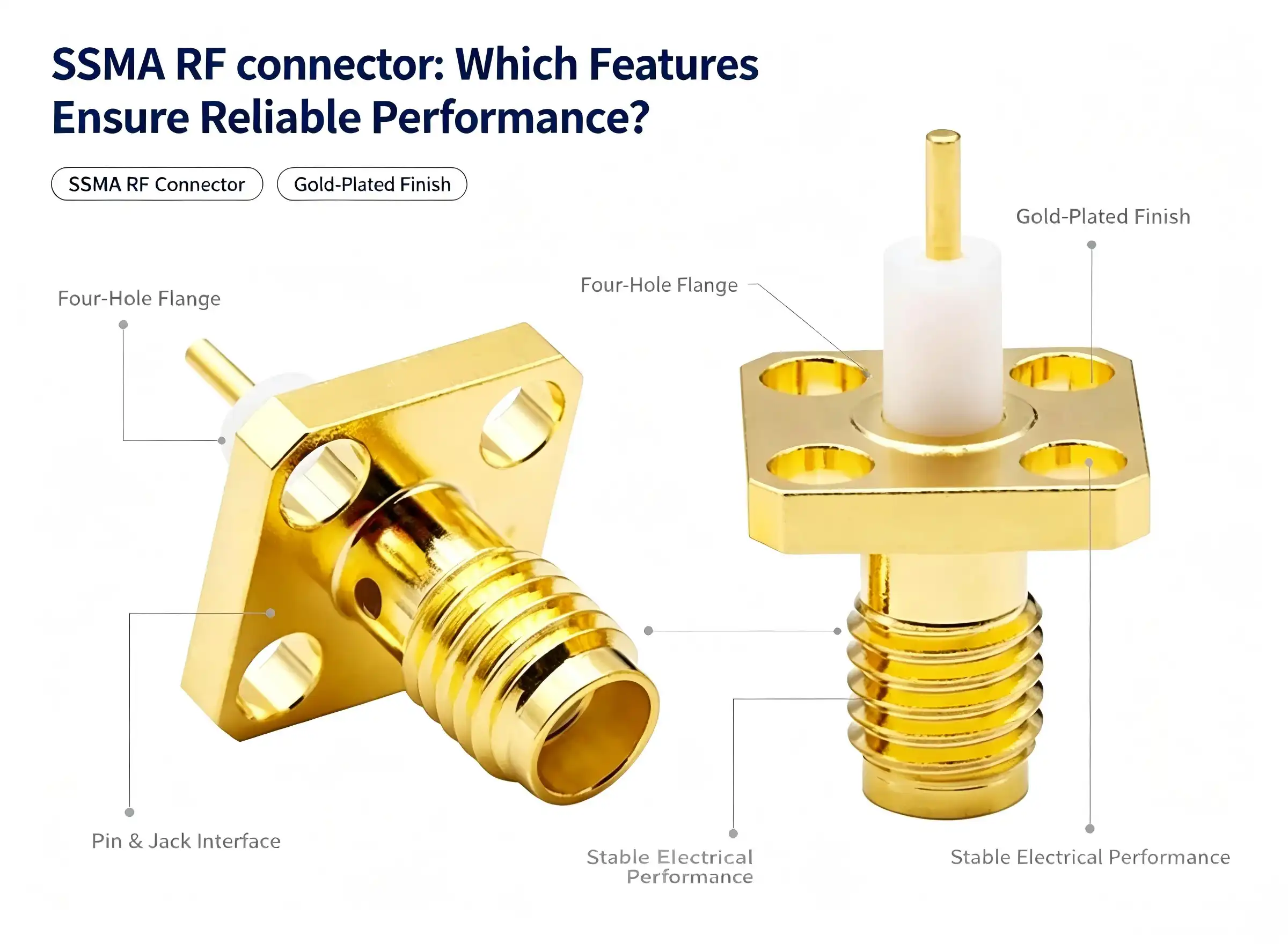
When engineers inquire about the aspects that contribute to dependable performance in an SSMA RF connector, the response is based on four pillars: selection of precision materials, tight tolerances, stable impedance management, and environmental robustness. These miniature coaxial connections handle DC to 34 GHz – with some types to 38 GHz – while retaining 50Ω characteristic impedance. The 10-36UNEF threaded coupling, gold-plated beryllium copper conductors and PTFE dielectric combine to provide minimal insertion loss and excellent signal integrity for demanding communications, radar and test-and-measurement applications.

Understanding SSMA RF Connector: Specifications and Functional Basics
The SSMA RF connection is simply a miniature version of the normal SMA connector, which was established in 1960 and was standardized under MIL-PRF-39012, MIL-STD-348, and CECC 22 160. Its small size makes it a must have when space is tight on the board and high frequency performance is not to be sacrificed.
Core Technical Specifications
The characteristic impedance is a constant 50Ω, from DC to 34 GHz with some high-performance models reaching 38 GHz. VSWR performance is less than or equal to 1.10:1 DC to 18 GHz, less than or equal to 1.15:1 18 to 27 GHz and less than or equal to 1.25:1 27 to 36 GHz. Genuine electrical resilience is shown in the insulation resistance of ≥5000 MΩ and the withstand voltage rating of ≥750 Vrms.
Cable Compatibility and Structural Design
The SSMA RF connection may be used with a selection of flexible and semi-rigid cables including RG174, RG316, RG188 and LMR-100. Crimping or soldering makes the connection secure by creating a mechanical and electrical link. The bent version is available in straight and 90° right-angle configurations and saves installation space in crowded equipment layouts. The coaxiality error following cable construction is strictly managed to reduce signal reflection throughout the transmission line.
Critical Features That Ensure Reliable Performance of SSMA RF Connectors
Knowing the difference between a good SSMA RF connector connection and a typical one may save engineers from expensive field problems. Reliable performance isn’t a single property — it’s the sum of a number of designed traits working together.
Materials That Drive Electrical and Mechanical Integrity
Inner conductor is made of beryllium copper or brass and gold plated. Contact resistance is ≤3 mΩ. The combination offers outstanding electrical conductivity and high elastic recovery, allowing the contact to retain constant pressure during hundreds of mating cycles. The outer conductor is brass, gold or nickel plated for corrosion protection but has an added knurled surface to make hand tightening easier. The dielectric is PTFE (Teflon), with a stable dielectric constant of εr = 2.1 – a value that remains constant across the complete working frequency range, maintaining impedance matching when other materials might wander.The following are the key performance parameters that distinguish these connectors for high frequency applications:
- Impedance consistency The 50Ω system impedance is maintained throughout the connection body, avoiding a reflection of the interface. Mixing with 75Ω cable systems incurs substantial signal attenuation and should be avoided.
- Mating durability: Mechanical plug-and-unplug life is rated ≥500 cycles and meets the requirements of standard lab and production testing without mechanical deterioration.
- Thermal endurance: The connections can operate at temperatures from -65°C to +165°C, making them suitable for aerospace, industrial, and outdoor communication applications where ambient conditions might be extreme.
- Torque-controlled coupling The 10-36UNEF thread has a torque of tightening of 0.45 to 1.1 N·m. Keeping inside this window reduces thread stripping and offers vibration resistant mechanical fastening.
These qualities, taken together, address the most prevalent failure mechanisms in high frequency connection applications, namely impedance mismatch, mechanical wear, corrosion and thermal fatigue.
SSMA RF Connector vs. Other RF Connectors: Making the Right Choice
The selection of a connector interface is a procurement choice with long-term implications. If the choice of an SSMA RF connector is wrong then boards have to be redesigned, cable assemblies replaced or poor system performance accepted.
How SSMA Compares to SMA and Other Interfaces
SMA connections in their standard form can handle up to 18 GHz and are used for broad RF applications such as WiFi antennas and portable radio devices. The SSMA RF connection, however, can reach up to 34–38 GHz, making it the appropriate option when you need bandwidth headroom — 5G millimeter-wave modules, phased-array radar and precision spectrum analysis equipment all benefit from the extra range. Physical dimension is another thing that differentiates: the lower footprint of the SSMA allows for greater density PCB layouts that SMA just can't match.BNC connections are limited to around 4 GHz and they're OK for low frequency lab work but they're not ideal for microwave operations. N-type connections are suitable for outdoor, weatherproof applications but are too bulky for small RF modules. TNC connections are threaded and reliable up to around 11 GHz in vibration situations. The SSMA offers a unique mix of miniaturization, high frequency, and mechanical security that none of these alternatives can match.

Procurement Insights: How to Source Quality SSMA RF Connectors
Sourcing considerations impact overall lifespan cost and product dependability as well. Things like certification credentials, customisation capabilities and supply chain responsiveness matter, too. Procurement managers need to look at more than unit pricing when evaluating vendors.
A quality SSMA RF connection must meet the requirements of MIL-PRF-39012, ISO quality management standards, and RoHS environmental guidelines. Suppliers who comply with MIL-STD-348 prove that they meet field-validated dimensions and performance standards in aerospace and military applications. When you are looking at a vendor, ask the seller for test data on VSWR, insertion loss, and mating durability - good vendors will provide these to you automatically.
Chuangyu (cymicrowave.com) produces SSMA RF connectors and entire cable assemblies to international standards from its Xi’an manufacturing facility, with an annual capacity of 500,000 RF components. Its R&D laboratory has 200 square meters of connection validation and bespoke engineering, allowing quick iteration on non-standard needs. Chuangyu’s technical team may engage directly on unique solutions for applications requiring millimeter-wave connections up to 110 GHz, waveguide-to-coaxial converters, or application-specific cable assemblies. It is a realistic SSMA RF connection provider for both pilot projects and mass manufacturing, with volume pricing structures and OEM/ODM assistance.
Ensuring Long-Term Performance: Installation and Maintenance Best Practices
The highest standard SSMA RF connector connection is subject to early degradation if installation procedures are not followed. The most important habit to cultivate is the torque discipline, always applying between 0.45 and 1.1 N·m during mating. Too much torque on the inner pin will distort it. Too little torque permits micro-motion that wears the contact surface.
Clean contact surfaces and threaded interfaces with anhydrous alcohol on a cotton swab every 3-6 months. Do not use abrasive tools or sandpaper on gold-plated surfaces, as this will destroy the protective coating and speed up oxidation. Let the alcohol evaporate completely before you reconnect. Fit dust caps to connections while not in use to avoid particle contamination.
We recommend an annual electrical check using a network analyzer. Replace immediately if VSWR is above 1.5 or insertion loss is noticeably higher than baseline. Signs of thread stripping, intermittent signal operation, or inability to mate smoothly are all indications that the connection should be removed from service and not used. Store between −20°C and +60°C, ≤60% relative humidity, away from corrosive gases and strong magnetic fields. Proper storage greatly increases the service life and maintains the quality of the plating.
Conclusion
The SSMA RF connection provides dependable performance by carefully combining the quality of materials, geometric accuracy, impedance control, and environmental robustness. These ssma RF connector products have gold-plated beryllium copper conductors, PTFE dielectric (εr ≈ 2.1), 10-36UNEF threaded coupling and working range of DC to 34 GHz making them ideal for 5G infrastructure, radar systems, laboratory instruments and industrial wireless networks. If you purchase them from an SSMA RF connection manufacturer who is qualified, and you maintain them following the published specifications, then they will function at or above their specified performance for the duration of their service life.
FAQ
What is the maximum operating frequency of an SSMA RF connector?
Standard SSMA RF connectors are rated for DC to 34 GHz. Certain high-performance variants extend this to 38 GHz. This range covers most 5G millimeter-wave, radar, and precision test applications currently in production.
Are SSMA and SMA connectors mechanically interchangeable?
No. Although both use threaded coupling and share 50Ω impedance, SSMA connectors use a 10-36UNEF thread while SMA uses a 1/4-36UNS thread. The two interfaces are dimensionally incompatible and require an adapter for interconnection.
What compliance standards apply to SSMA RF connectors?
SSMA connectors are governed by MIL-PRF-39012, MIL-STD-348, and CECC 22 160. For commercial procurement, ISO quality management certification and RoHS compliance are additional indicators of a credible supplier.
Can SSMA connectors be used with semi-rigid cables?
Yes. SSMA RF connectors are compatible with both flexible cables such as RG174 and RG316 and semi-rigid cable types. Connection method — crimping or soldering — should be selected based on cable type and application vibration requirements.

Partner with Chuangyu for Precision SSMA RF Connector Solutions
Chuangyu brings nearly two decades of RF connector manufacturing expertise directly to your procurement process. As a trusted SSMA RF connector manufacturer, we offer certified connectors, custom cable assemblies, and millimeter-wave components up to 110 GHz — all backed by rigorous in-house testing. Visit cymicrowave.com to explore our catalog or request a custom solution. Contact our engineering team at chuangyuwz01@cymicrowave.com to discuss bulk pricing, OEM requirements, or application-specific configurations.
References
1. IEEE Transactions on Microwave Theory and Techniques — 2021
2. MIL-PRF-39012: General Specification for Connectors, Coaxial, Radio Frequency — U.S. Department of Defense, 2018
3. MIL-STD-348: Interface Standard for RF Connector Interfaces for MIL-PRF-39012 — U.S. Department of Defense, 2019
4. CECC 22 160: Sectional Specification for RF Coaxial Connectors — CENELEC, 2015
5. Microwave Engineering, David M. Pozar — Wiley, 4th Edition, 2011
6. Journal of Electronic Testing: Theory and Applications (JETTA) — Springer, 2022
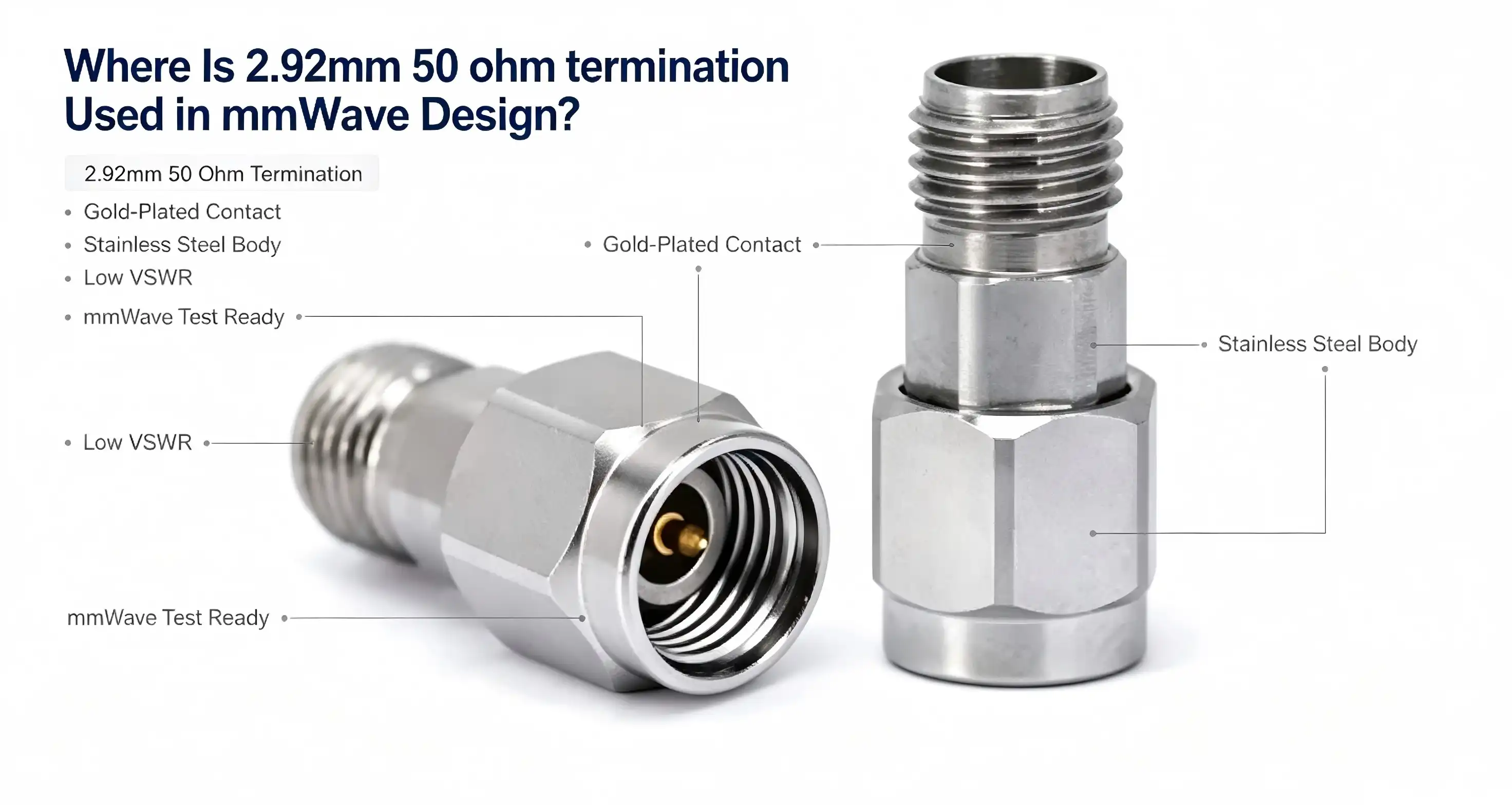
The 2.92mm 50 ohm termination is a precise coaxial load for mm-wave systems from DC to 40GHz. It absorbs leftover signal energy at unused ports in mmWave architecture to reduce reflections that affect measurement accuracy and system stability. It is used by engineers in vector network analyzer (VNA) calibration setups, 5G base station modules, radar transmission chains and high-power RF subsystems. With its regulated impedance and low VSWR, it is an absolute must when signal integrity, port isolation and dependable power absorption are non-negotiable criteria.

Application Areas of 2.92mm 50 Ohm Terminations in mmWave Design
And when engineers want to find out where this component really earns its keep, the answer covers three high-stakes sectors.
Millimeter-Wave Test and Measurement
In VNA measurement applications, the 2.92mm 50 ohm termination provides a high-power terminal load during system calibration and device characterization up to 40GHz. It captures signal energy at the idle ports of mm-wave signal generators and network analyzers, eliminating standing wave pollution from distorting S-parameter data. The precision of calibration in the 40 GHz band testing is very much a function of the stability of the termination VSWR. Any model that wanders over 1.35 will add quantifiable inaccuracy to the return loss and the insertion loss values. This is why monthly VSWR pre-testing is a suggested discipline.
5G Infrastructure and Radar Systems
The 2.92 mm 50-ohm termination is used as a dummy load and for impedance matching for 5G base station microwave modules operating in millimeter-wave frequency ranges. It is used in radar transmission systems to separate unneeded branches in beamforming networks and phased array front ends. This component satisfies the specifications for terminations used in high-power RF transmission connections where the instantaneous peak power handling of up to 1000 W is required under particular transient situations. Its air medium topology makes the dielectric loss minimal, which preserves the efficiency of high-power transmission chains.
Military and Scientific Research Platforms
Military RF subsystems have tight criteria for signal absorption. The 2.92 mm 50-ohm termination satisfies these requirements by efficiently absorbing reflected energy throughout the temperature extremes of -55°C to +125°C. It is used by R&D engineers in laboratory situations for terminating open ports in antenna measurement chambers, electronic warfare test benches, and high-frequency signal conditioning modules. The inner conductor is made of gold-plated beryllium copper, which resists oxidation over prolonged service life, important for long duration scientific installations where replacement of the connection has a substantial cost and schedule effect. The three most important application areas are summarized below:
- Millimeter-wave test and measurement: Used as a calibration standard load in 40 GHz band configurations for VNAs and signal generators, providing accurate measurements by absorbing idle-port reflections with VSWR < 1.35.
- 5G and Radar Communication: Reliable dummy load function and impedance matching for high-power microwave modules and phased array systems, withstanding instantaneous peak power events up to 1000 W.
- Military and R&D settings: Delivers steady RF absorption from -55°C to +125°C working temperatures for electronic warfare benches, antenna test chambers and long-duration research instrumentation.
These three application profiles represent the widest range of mmWave system design scenarios that are active in the U.S. market today, including applications that require components such as a 2.92mm 50 ohm termination for reliable signal performance.

How to Test and Validate 2.92mm 50 Ohm Terminations
VNA-Based Performance Verification
Terminate the 2.92mm 50 ohm to a calibrated VNA port and sweep from DC to 40 GHz. Measure return loss throughout the whole band. A complying equipment will show return loss better than around 17 dB, which corresponds to VSWR ≤ 1.35. Any departure from this threshold is an indication of deterioration of the resistive element or contamination of the connection contact. After every 15 insertion and withdrawal cycles, wipe the connection end face with isopropyl alcohol swabs, especially the gold-plated layer. Never use metal tools on the air medium contact. Mechanical abrasion will change the dielectric geometry forever and change the impedance.
Storage, Maintenance, and Service Life Management
Keep idle devices at temperatures ranging from -20°C to +60°C and relative humidity of 50% or below. Monthly VSWR pre-test: units over 1.35 need factory recalibration. Full band VSWR and power capacity testing with a network analyzer is recommended before putting the device back into operation after more than 1000 working hours or after a major mechanical stress event. If the humidity level of the working environment exceeds 60%, please install an IP67 sealing cover over the connection interface to prevent moisture and corrosive gases from entering the air medium structure.
Comparison and Procurement Guidance for 2.92mm 50 Ohm Terminations
The 2.92mm interface is a practical sweet spot for those who use coaxial terminations. The 2.4mm size is useful at 50 GHz but is somewhat more expensive per unit, and fewer mating cycles are available in big volume test applications. The 3.5mm and SMA connectors only cover up to 26.5 GHz and 18 GHz, respectively, which is not sufficient for the calibration operations in the 40 GHz range. The 2.92mm 50 ohm termination addresses the bulk of current mmWave design needs without the premium of sub-millimeter connections.
Certified 2.92mm terminations with verifiable product warranties and established distribution channels are produced by reliable providers like as Amphenol, Pasternack and HUBER+SUHNER. Qualification risk is lowered for procurement managers procuring in bulk via vendor-provided test data, RoHS compliance documents, and MIL-spec equivalence assurances. Manufacturers who develop and build RF components in-house may be able to provide custom solutions, such as different torque parameters, other housing materials, or embedded heat monitoring.
Chuangyu manufactures 2.92mm 50 ohm terminations at its Xi'an facility, which has an annual production of 500,000 RF components. With over 20 years of process expertise in producing coaxial connectors, dimensional tolerances and plating standards are strictly maintained across production runs, lowering the burden of incoming inspection for OEM and ODM customers.
Summary and Best Practices for Implementing 2.92mm 50 Ohm Termination in mmWave Design
For mmWave work, the correct 50 ohm termination is selected based on four non-negotiable parameters: impedance stability at the rated frequency, VSWR over the full DC to 40 GHz band, power handling at the expected operating temperature, and mechanical durability for the anticipated mating cycle count. Proper termination at each unused port avoids measurement error due to reflections and protects active components from standing wave stress.
By partnering with a supplier that has confirmed production data, can accommodate bespoke configurations, and responds swiftly to procurement requests, you decrease both technical risk and schedule exposure. mmWave design margins are tight, and component variability at the termination level propagates to the system-level performance. The easiest way to achieve a reliable, repeatable mmWave platform is to use a proven 2.92mm 50 ohm termination with documented test traceability.

FAQ
What is the maximum operating frequency of the 2.92mm 50 ohm termination?
The 2.92mm 50 ohm termination supports frequencies from DC to 40 GHz, making it compatible with the majority of current millimeter-wave test, 5G, and radar applications.
How much power can this termination handle continuously?
At 25°C, the rated continuous power is 10 W. At 125°C, this derates to 5 W. The instantaneous peak power tolerance reaches 1000 W under defined transient conditions.
How often should the connector interface be cleaned?
Clean the end face with isopropyl alcohol swabs after every 15 mating cycles. Focus on the gold-plated inner conductor surface and avoid any metal-contact cleaning tools.
When should a unit be returned for factory recalibration?
Return any unit for recalibration when monthly VSWR testing exceeds 1.35, or after the component accumulates more than 1000 cumulative operating hours, or following a significant mechanical shock event.
How does the 2.92mm termination compare to 3.5mm and SMA types?
The 3.5mm interface covers up to 26.5 GHz, and SMA up to 18 GHz. The 2.92mm 50 ohm termination extends usable range to 40 GHz, filling the gap between standard SMA-based systems and higher-cost 2.4mm precision components.

Reach Out to Chuangyu — Your Trusted 2.92mm 50 Ohm Termination Supplier
Chuangyu delivers precision-built mmWave components, including the 2.92mm 50 ohm termination, from our Xi'an production base to customers across communications, defense, and test industries. As a reliable 2.92mm 50 ohm termination manufacturer, we support OEM orders, custom configurations, and rapid sampling. Our engineering team responds directly to technical specifications and procurement timelines. Contact us at chuangyuwz01@cymicrowave.com or visit cymicrowave.com to request datasheets or a quotation.
References
1. Pozar, D. M. Microwave Engineering, 4th ed. Wiley, 2011.
2. Bahl, I. J. Fundamentals of RF and Microwave Transistor Amplifiers. Wiley, 2009.
3. IEEE Standard 287-2007. IEEE Standard for Precision Coaxial Connectors (DC to 110 GHz). IEEE, 2007.
4. Collin, R. E. Foundations for Microwave Engineering, 2nd ed. Wiley-IEEE Press, 2001.
5. Rehnmark, S. "On the Calibration Process of Automatic Network Analyzer Systems." IEEE Transactions on Microwave Theory and Techniques, 1974.
6. Rytting, D. "Network Analyzer Accuracy Overview." Proceedings of the 58th ARFTG Conference, 2001.
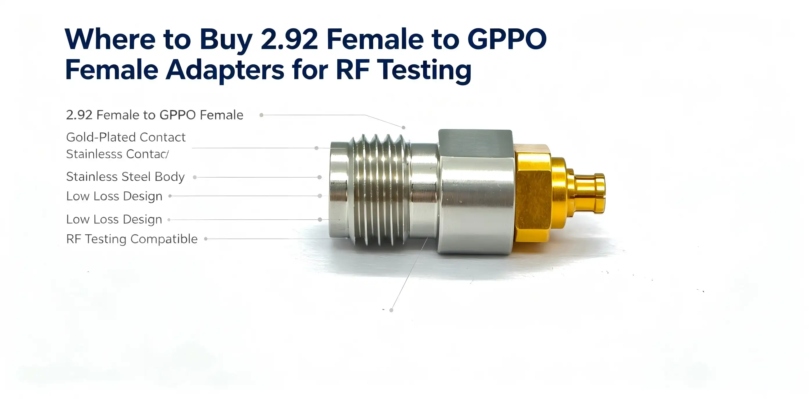
You may look for direct manufacturers such as Chuangyu (cymicrowave.com), authorized distributors like Mouser and Digi-Key, and B2B platforms for a dependable 2.92 female to GPPO female adapter for RF testing. For precise millimeter-wave testing (DC to 40 GHz with VSWR ≤1.35 and 50Ω impedance), there’s no room for error in selecting a proven provider. Whether you are an R&D engineer, procurement manager, or test systems integrator, this book will teach you how to identify such adapters, who to trust, and how to buy them with confidence.

Understanding 2.92 Female to GPPO Female Adapters
What Makes This Cross-Series Adapter Unique
A 2.92 mm female to GPPO (SSMP) female adapter joins two different kinds of millimeter wave connectors. The GPPO (SSMP) female end is for ultra-compact push-in connections used in high-density RF modules and phased array radar systems. On the other end is a 2.92mm male pin interface, used on instruments like vector network analyzers and spectrum analyzers. This cross-series design addresses a genuine pain issue – mismatched interfaces among millimeter-wave test equipment. The GPPO connection is about 30% smaller than a normal SMP connector and has an outside diameter of around 2.4mm. Its small size makes it a must in tight circuit situations where space is a premium but signal integrity must be sacrificed.
Core Technical Specifications You Should Know
The outside conductor of the adapter is stainless steel, passivated to resist corrosion and mechanically durable. The inner conductor is beryllium copper with gold plating. This reduces ohmic loss while transmitting high-frequency signals. The dielectric insulator is PTFE. The characteristic impedance is 50Ω from DC to 40GHz across the working range. Some important electrical and mechanical parameters are:
- Frequency of work: DC-40 GHz (for 5G NR, microwave backhaul, and radar testing); VSWR: ≤1.35 (little signal reflection throughout the frequency spectrum)
- 2.92mm connection torque: 0.8–1.1 Nm (needs a calibrated torque wrench)
- GPPO Push in tolerances Radial ≤±0.25mm, Axial ≤+0.25mm
- Mating cycle life: ≥500 insertions, suitable for recurrent laboratory and production testing
The performance specifications meet IEC 61169 for coaxial RF connections and are suitable for harsh measurement situations with 2.92 female to GPPO female adapter applications.
How to Choose the Right 2.92 to GPPO Female Adapter for RF Testing
When requesting a price, please ensure that you have defined the signal frequency range, the ambient working conditions, and predicted mating cycles. If your test bench is always running in a shielded environment up to 40 GHz, then the proven DC–40 GHz range of the adapter is a perfect fit. For higher frequency applications close to 67 GHz, be aware that the GPPO connection design can theoretically handle this range, but the adapter assembly is only certified up to 40 GHz—do not exceed this limit. If you need measurement-grade performance, you cannot compromise on VSWR and insertion loss. Reflections at a VSWR over 1.35 can distort your S-parameter measurements, which is particularly important when characterizing semiconductor RF chips or validating 5G base stations. Here are the quality elements you should focus on while assessing suppliers:
- Material traceability: Gold-plated beryllium copper inner conductors and passivated stainless steel bodies should be delivered with material certifications
- Impedance uniformity: Confirm 50 ohm impedance over the whole rated frequency range and not only at a particular test point
- Insertion loss documentation: Get measured insertion loss data, not just spec sheet minimums.
- Compliance Certification: Look for goods that meet the MIL-PRF-39012 or similar specifications for use in severe environments
These parameters differentiate dependable millimeter wave adapters from generic components that may not last long under test circumstances. Once technical congruence is confirmed, it is easy to evaluate existing providers.
Where to Buy 2.92 Female to GPPO Female Adapters — Trusted Suppliers and Platforms
This sort of RF coaxial adapter may be ordered in a number of ways, each with its own benefits depending on how many you need to purchase, whether you need them customized, and how fast you need delivery. RF adapters from companies like Amphenol, Pasternack, and Radiall are stocked by global electronics wholesalers such as Mouser Electronics, Digi-Key, and RS Components. These platforms provide fair pricing, access to datasheets, and dependable logistics, making them great for low-volume prototype purchases.
But they seldom provide for specific interface needs or bulk price agreements. If you are an R&D lab or an OEM company with large orders and special requirements such as changed torque ratings, different plating, or non-standard connection pairings, it is usually easier to deal directly with the manufacturer. This approach reduces the specification-to-delivery period and allows for technical participation in the design phase. Chuangyu (cymicrowave.com) is a producer and direct provider of precision RF connectors, millimeter wave cable assemblies, and cross-series adapters, including 2.92 female to GPPO female adapter.
Chuangyu has approximately 20 years’ expertise in producing RF components, with an annual output of 500,000 RF components and a specialized R&D lab, serving the military, semiconductor, 5G communications, and medical instruments industries. Orders are managed from the Xi’an production base with response cycles 20% shorter than the industry norm on average.
Understanding Pricing and Procurement Logistics
The price of precise millimeter wave adapters depends on the quality of the materials, the production tolerances, and the quantity of the order. Good quality GPPO female adapters with a Standard 2.92 inlet normally sell for between $15 and $80 each. So buying in bulk from a manufacturer brings the price down a lot per unit, and also allows more control over the specs. International B2B Buyers: Please note customs classifications under HS Code 8544.42 or 8536.90 depending on jurisdiction. Lead Times: Standard Stock 2-6 weeks. Custom Builds: 4-8 weeks. Long-term supplier agreements with explicitly specified quality milestones mitigate procurement risk and stabilize your supply chain against component shortages.
Common Use Cases and Applications in RF Testing
The 2.92mm to GPPO female adapter is specially designed for demanding RF test applications. So here are the key application fields where this adapter brings real value:
- 5G and microwave testing: Interface conversion between vector network analyzers and DUT ports for 5G base station validation, microwave backhaul testing, and radar system characterization up to 40 GHz without compromising signal integrity
- RF development: Semiconductor enables wafer-level test probe compatibility with benchtop measurement devices to accelerate development verification cycles for RF chip characterisation
- Aerospace and Defense: High reliability requirements are met for phased array radar component screening and RF testing of military electronic equipment, where VSWR instability or unexpected attenuation causes mission-critical failures.
- System integration test: Matches interfaces across mixed-generation millimeter-wave equipment, improving utilization of current test infrastructure without the need for expensive hardware changes.
Such applications indicate that measurement confidence is directly affected by the quality of the adaptor. A bad or misaligned adapter might result in a poor VSWR measurement that can invalidate an entire test run. Clean interfaces with a specific RF swab using anhydrous alcohol for maintenance. Store adapters in shielded, dry enclosures within the temperature range of –10°C to +40°C and humidity ≤60% RH. Inspect before each use for deformations of the outer conductor, deterioration of the coating, or oxidation of the socket. If you get any abrupt VSWR rise during testing, you should investigate immediately before proceeding.
Conclusion
It’s not only about pricing in terms of finding the correct 2.92 female to GPPO female adapter; it’s about quality of materials, VSWR performance, interface tolerances, and supplier dependability. With gold-plated beryllium copper conductors and a mating life of ≥500 cycles, this adapter class is designed for demanding applications from 5G validation to semiconductor research and military testing, with an operating range from DC to 40 GHz. Whether sourcing from wholesalers or directly from a manufacturer like Chuangyu, you should always emphasize verified specs and traceable quality to maintain the integrity of your test systems.
FAQ
What is the maximum operating frequency of this adapter?
The 2.92 female to GPPO female adapter supports DC to 40 GHz. This covers the majority of 5G sub-6 GHz and millimeter-wave test scenarios, as well as radar and microwave communication equipment validation.
Is this adapter compatible with high-power RF applications?
This adapter is designed for measurement-grade, low-power RF signal transmission. It is not intended for high-power RF transmission applications. Always verify rated power limits with your supplier before deployment.
How do I confirm physical compatibility with my existing test equipment?
Verify that your instrument port accepts a 2.92mm male pin, and that your device under test or cable assembly uses a GPPO (SSMP) male connector. The push-in GPPO end accommodates radial misalignment of ±0.25mm, which suits most standard test setups.
How long does the adapter last under repeated use?
With a rated mating cycle life of ≥500 insertions, this adapter suits high-throughput test environments. Cleaning and proper torque application on the 2.92mm end (0.8–1.1 Nm) extend service life significantly.

Get Your Custom Quote from Chuangyu Today
Chuangyu delivers precision-engineered 2.92 female to GPPO female adapters built to meet the rigorous demands of millimeter-wave RF testing. As an experienced 2.92 female to GPPO female adapter manufacturer, we support OEM, ODM, and custom configurations with full technical documentation. Visit cymicrowave.com to explore the full product portfolio, or contact our engineering team directly at chuangyuwz01@cymicrowave.com to request a datasheet or bulk pricing quote tailored to your project.
References
1. IEEE Microwave Magazine — "RF Connector Standards and Measurement Accuracy in Millimeter-Wave Test Systems," 2022
2. Microwave Journal — "GPPO and SSMP Connector Technology for High-Density RF Modules," 2021
3. IEC 61169-15 — "Radio-Frequency Connectors: Part 15: Sectional Specification for Cables with 2.92mm Connectors," International Electrotechnical Commission, 2020
4. Journal of Electronic Testing: Theory and Application (JETTA) — "Signal Integrity Considerations in Precision RF Adapter Selection," Springer, 2021
5. MIL-PRF-39012F — "Connectors, Coaxial, Radio Frequency, General Specification For," U.S. Department of Defense, 2019
6. High Frequency Electronics — "Advances in Ultra-Small RF Connector Design for 5G and Millimeter-Wave Applications," 2023
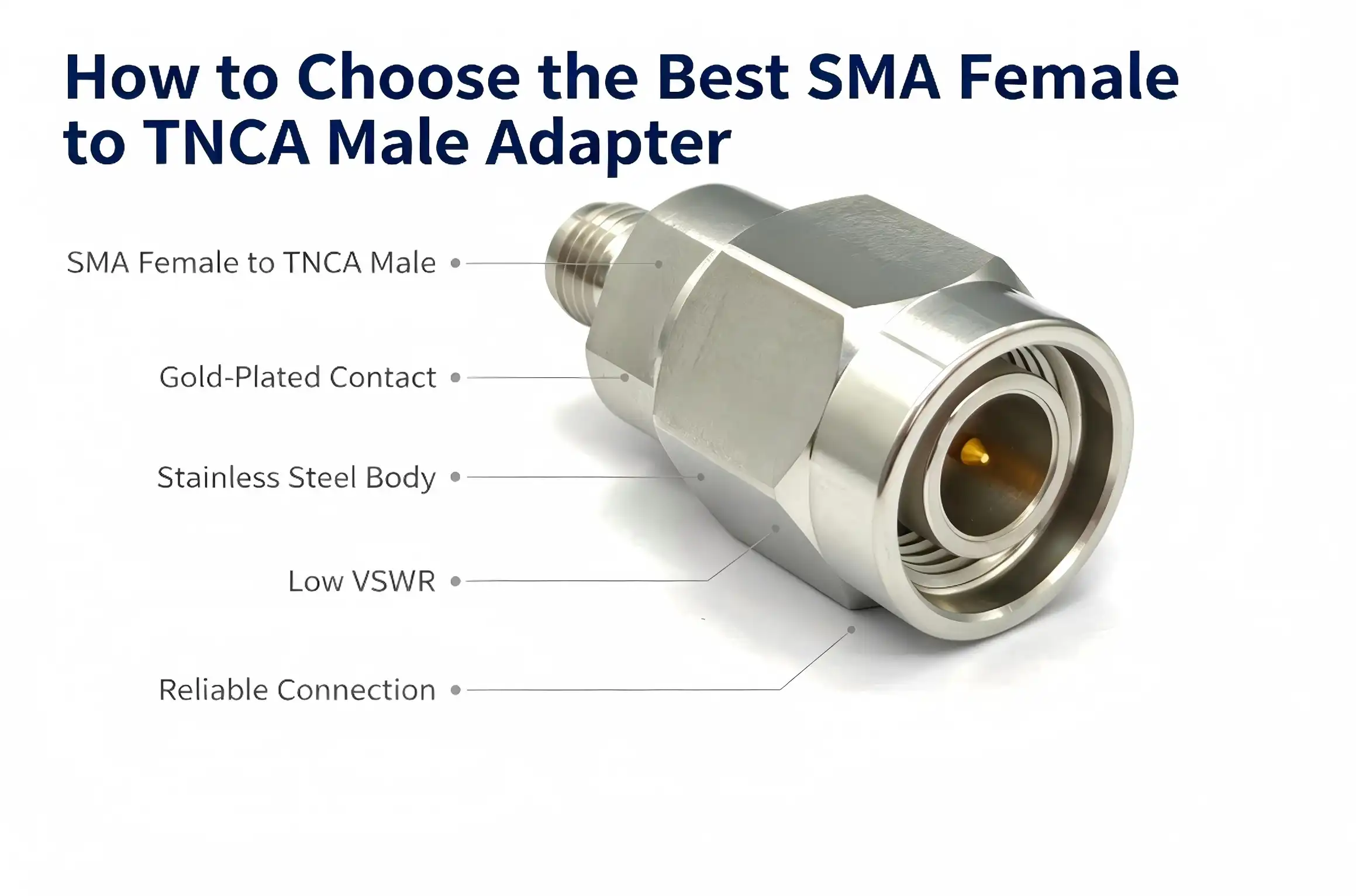
Choose the correct SMA female to TNCA male adaptor according to your frequency range, impedance needs, and mechanical requirements. This coaxial adapter is cross-series and adapts a SMA female jack, a small microwave standard interface, to a TNCA male connection with precise exposed pins. For B2B procurement in RF test, telecom, or industrial applications, the optimum SMA female to TNCA male adapter should have VSWR ≤1.25 over DC to 18 GHz, have 50Ω impedance using PTFE dielectric, and be rated for ≥500 mating cycles. Quality of materials, torque compliance, and dependability of suppliers are other determining criteria.

Understanding SMA Female to TNCA Male Adapters
What This Adapter Actually Does
An SMA female to TNCA male adapter is a cross-series RF coaxial component used for the conversion between two different microwave connection standards. The SMA’s female end is an inside jack, a common small microwave interface. The TNCA’s male end has precision exposed pins for high-precision signal relay. Used together, they provide a smooth interface conversion between SMA receiver ports and TNCA transmitter ports in demanding test and measurement situations.
Core Technical Specifications
This adapter’s construction and materials directly impact its field performance. These are the main specs that matter most to hardware developers and procurement managers:
- Outer conductor: passivated stainless steel for great mechanical strength and corrosion resistance in tough lab or industrial settings.
- Inner conductor: Beryllium copper, gold-plated for low-loss, reliable transmission of high-frequency signals up to 18 GHz.
- Dielectric material: PTFE (polytetrafluoroethylene) - Chosen for uniform dielectric characteristics offering 50Ω impedance matching across the whole working range.
- Frequency Range: DC to 18 GHz, encompassing most wireless communication, radar, and precision measurement applications.
- VSWR: ≤1.25 indicates a little reflected signal and high transmission efficiency.
- Mating torque: SMA female end 0.5–0.8 Nm; TNCA male end 0.8–1.1 Nm.
- Plug and pull life: > 500 cycles for regular usage in high-frequency test procedures.
These specs prove that a well-built SMA female to TNCA male adapter is not a passive accessory but a precision microwave component whose design directly impacts system accuracy.

Criteria for Choosing the Best SMA Female to TNCA Male Adapter
Electrical Performance First
When analyzing any RF coaxial adapter, cost should be secondary to electrical performance parameters. VSWR is a direct measurement of how well the adapter passes a signal. A VSWR of ≤1.25 from DC to 18 GHz represents less than 1% reflected power, which is important when connecting to devices such as vector network analyzers or spectrum analyzers. Also check insertion loss. Low insertion loss means the signal integrity across the signal chain is maintained. But more importantly, the 50Ω impedance continuity across the PTFE dielectric means that the adapter integrates without causing the impedance discontinuities that distort readings. However, engineers working on 5G base station modules or microwave circuit R&D cannot afford any signal deterioration, no matter how little, at crucial test nodes.
Material Quality and Mechanical Durability
Material selection is a direct reflection of lifespan and dependability. Passivated stainless steel outer conductors are also more resistant to oxidation and physical deformation than brass counterparts under high-cycle test conditions. The gold-plated beryllium copper inner conductors retain contact resistance for hundreds of mating cycles without any surface deterioration. Mechanical durability is also a matter of torque compliance. If adapters do not hold structural integrity at the rated torque levels, from 0.5 to 0.8 Nm at the SMA end and from 0.8 to 1.1 Nm at the TNCA end, connectors may be damaged in test settings, and the whole system is compromised. The torque ratings are always specified and verified by the product you are sourcing.
Supplier Credibility and OEM Capability
For OEM manufacturers, system integrators, and R&D laboratories, the ability of the supplier to deliver consistent batch quality and customized assistance is as vital as the requirements of the adapter. Seek providers with verifiable quality procedures and documented test results, and who can accommodate non-standard interface needs. Brands with established distribution networks in North America are commonly cited in the industry, such as Pasternack, Amphenol, and TE Connectivity. At the same time, precision manufacturers headquartered in China, such as Chuangyu, are increasingly competing on specification parity with significant customization capabilities and shorter lead times.
Practical Tips and Best Practices for Using SMA Female to TNCA Male Adapters
Installation and Pre-Use Inspection
Always check the outside conductor for deformation before mating any SMA female to TNCA male adapter. Make sure the coating is not peeling or pitted and that the female socket and male pin are not oxidized or physically damaged. Replace the adapter immediately if there is any irregularity. Use a calibrated torque wrench during installation. In precision microwave connections, structural failure often results from oblique insertion or over-tightening beyond specified torque levels. Applying the torque uniformly protects the adapter and the attached instruments.
Signal Control and Environmental Setup
The test signal frequency should be firmly within the operating range of DC to 18 GHz. Excessive power ratings may induce thermal breakdown of the PTFE dielectric. To reduce the effects of external electromagnetic interference that may distort measurement baselines, especially for 5G R&D and vector network analyzer calibration work, do high-frequency testing in a shielded container.
Cleaning, Storage, and Fault Response
Clean connection interfaces using RF-grade swabs soaked in anhydrous alcohol. This eliminates oxide coatings and dust buildup that increase contact resistance over time. Store the adapters in a sealed, corrosion-free container at temperatures between -10°C and 40°C and humidity ≤60% RH. If the VSWR increases quickly or signal attenuation is abnormal during the test, stop testing immediately. Check the adapter for wear and make sure the connection is properly placed. Do not use a defective adapter. This may cause a series of measurement mistakes and harm to connected equipment.
Conclusion
Choosing the best SMA female to TNCA male adapter is a comprehensive selection process – not a series of check marks – that takes into account electrical characteristics, material integrity, mechanical ratings, and supplier dependability. Precision microwave testing requires coverage from DC-18 GHz and VSWR ≤1.25, for which a combination of gold-plated beryllium copper inner conductors, passivated stainless steel housing, and PTFE dielectric in an adapter is used. To maintain measurement accuracy and long-term system availability, effective procurement teams combine technical standards with supply chain considerations such as support for customization and consistent batch quality.
FAQ
What is the difference between an SMA female to TNCA male adapter and an SMA male to TNCA female adapter?
The polarity determines which port each adapter connects to. An SMA female to TNCA male adapter receives an SMA male plug on one end and plugs a TNCA male pin into a TNCA female port on the other. Reversing polarity—SMA male to TNCA female—serves the opposite connection direction. Confirm your instrument and device-under-test port genders before ordering.
How do I verify compatibility before purchasing?
Cross-reference the connector genders, impedance (50Ω), and operating frequency range against your instrument's specifications. For vector network analyzers and spectrum analyzers, ensure the adapter's VSWR ≤1.25 rating aligns with your calibration accuracy requirements.
Is a waterproof variant necessary for my application?
Standard passivated stainless steel housing provides strong corrosion resistance for most lab and indoor industrial environments. Sealed waterproof variants are advisable for outdoor base station work or high-humidity production floors. Consult your supplier about environmental rating requirements specific to your deployment.
What torque tool should I use?
A calibrated RF torque wrench set to 0.5–0.8 Nm for the SMA end and 0.8–1.1 Nm for the TNCA end is the correct choice. Standard hand-tightening does not provide the precision needed for high-frequency microwave connectors.

Partner with Chuangyu for Precision RF Adapter Solutions
Chuangyu offers rigorously engineered SMA female to TNCA male adapters built for DC–18 GHz performance and ≥500-cycle reliability—trusted by RF engineers across telecom, semiconductor testing, and medical device industries. As a dedicated SMA female to TNCA male adapter manufacturer and supplier, Chuangyu supports OEM customization, bulk procurement, and responsive global shipping. Contact our team directly at chuangyuwz01@cymicrowave.com or visit cymicrowave.com to request specifications and pricing.
References
1. Pozar, David M. Microwave Engineering, 4th ed. Wiley, 2011.
2. IEEE Standard 287-2007: IEEE Standard for Precision Coaxial Connectors (DC to 110 GHz). IEEE, 2007.
3. RF Globalnet. Connector Selection Guide for Microwave and Millimeter-Wave Applications. RF Globalnet Industry Reports, 2022.
4. Amphenol RF. RF Connector Application Guide: Inter-Series Adapters and Signal Integrity Considerations. Amphenol Technical Publications, 2021.
5. IEC 61169-15: Radio-Frequency Connectors — Part 15: Sectional Specification for SMA Connectors. International Electrotechnical Commission, 2013.
6. Richardson RFPD. Microwave Component Procurement Best Practices for B2B Electronics Buyers. Richardson RFPD Technical Resources, 2023.
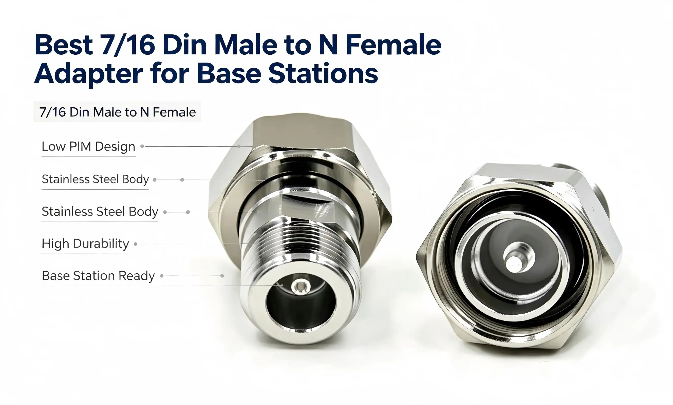
In terms of base station communication, the 7/16 DIN Male to N Female adapter is one of the most reliable inter-series RF transition parts available today. This adapter is designed to connect high-power DIN male connectors to standard N female ports, with constant 50Ω impedance, VSWR ≤1.3, and a broad frequency range from DC to 18 GHz. Whether implementing 5G infrastructure, supporting existing telecom systems, or conducting laboratory RF experiments, the DIN to N adapter you choose directly affects signal quality, system uptime, and long-term total cost of ownership.

Understanding the 7/16 DIN Male to N Female Adapter
Interface Architecture and Material Construction
The male DIN has a 7/16-28UNEF thread structure. Its outer conductor has tiny threads which mate to DIN female equipment with regulated torque – usually 1.0 to 1.5 N·m – that provide both mechanical hardness and vibration resistance. The inner conductor is a robust gold-plated pin providing a secure connection to the socket. The female end has a 5/8"-24UNEF thread configuration. Its inner conductor is an elastic socket that fits exactly with N male pins. Proper alignment of the threads during engagement is crucial to avoid stripping.
Material selection is critical to long-term dependability. The inner conductor is beryllium copper with a gold coating. The contact resistance is ≤2 mΩ. The exterior conductor is brass or stainless steel and is surface-coated with gold or nickel plating for corrosion protection and EMI shielding; The PTFE insulating medium has a steady dielectric constant εr≈2.1 across the whole frequency spectrum, such that the signal reflections remain low.
Electrical and Mechanical Performance
This coaxial adapter is designed for 4G/5G base stations, satellite ground equipment, and precise RF measurement setups from DC to 18 GHz with a standing wave ratio of ≤1.3. The mechanical durability is ≥ 500 insertion cycles, and the vibration resistance is MIL-STD-202 compliant to guarantee dependable operation on mobility platforms like cars and airplanes.
Comparing Top 7/16 DIN Male to N Female Adapters for Base Stations
Not all RF adapters on the market will provide the same quality of signal integrity or field endurance. Procurement engineers considering DIN-to-N transition adapters must carefully review these key performance indicators. Below, we summarize the qualities of good quality 7/16 Din Male To N Female Adapter and poor quality adapters:
- Signal integrity: Premium adapters provide less than 0.3 dB insertion loss at 2 GHz and a VSWR of ≤1.3 over the whole rated band, minimizing disturbance to the signal chain in high-power base station situations.
- Mechanical Durability: Military-grade vibration compliance (MIL-STD-202) and ≥500 mating cycles are important in field deployments where connections are often reconnected for maintenance or system integration.
- Weather resistance: Stainless steel outer conductors with nickel or gold coating withstand oxidation in coastal or industrial conditions. Dust caps on both ends greatly increase service life.
- Impedance continuity: PTFE-insulated transitions maintain a 50Ω characteristic impedance throughout the body of the adapter, avoiding reflection spots that decrease the wideband performance.
Together, these variables decide if an adapter survives performance throughout a five- to 10 year deployment lifecycle. Cheaper alternatives, such as reducing plating thickness or PTFE purity, usually fail within 18 months in outdoor base station environments, creating unforeseen maintenance expenses significantly greater than the initial savings. The other point to make is with regard
to the orientation. A 7/16 DIN male-to-N female adapter is used to connect a DIN male cable or module output to an N female port on an antenna or instrument. The N Male to 7/16 DIN Female arrangement is the opposite topology. One typical mistake in RF system integration procurement is to get the gender orientation incorrect.
How to Choose the Best 7/16 DIN Male to N Female Adapter for Your Base Station
The correct adapter relies on your particular network design. For 5G NR mid-band installations running below 6 GHz, a DC-18 GHz certified DIN-to-N adapter with VSWR ≤1.3 easily covers the needed spectrum with enough buffer. If you are dealing with satellite ground stations or microwave backhaul lines over 10 GHz, you will want to verify that the insertion loss is within specification at these higher frequencies.
IP-rated or weatherproofed designs, stainless steel housings, and dual-seal dust closures are required for outside installations. Brass exterior conductors with conventional gold plating are fine for indoor lab or OEM integration settings, but you still need constant impedance matching for accurate measurements.
Large-volume OEMs and ODMs may also want to assess a supplier’s ability to provide unique configurations such as non-standard thread lengths or different plating finishes to improve procurement flexibility. For example, Chuangyu has in-house R&D and precise production capability to assist the creation of unique non-standard RF connectors.
Installation and Maintenance of 7/16 DIN Male to N Female Adapters
The majority of connection problems are from improper installation. Carefully align the threads before joining — 5 to 8 twists on both the DIN male and N female ends. Torque within spec: 1.0-1.5 N·m on DIN male end, 0.8-1.2 N·m on N female end. Do not exceed the rated torque, or the threads will be stripped, or the inner conductor will be deformed. Using a 7/16 Din Male To N Female Adapter with proper installation procedures helps maintain reliable signal transmission and connection performance.
For routine maintenance, wipe both conductor surfaces with an alcohol-moistened cotton swab every 3 to 6 months or after exposure to severe conditions. Let it dry completely before rejoining. For essential installations, ensure insertion loss is less than 0.5 dB and VSWR is less than 1.5 using a network analyzer every 6 to 12 months. If any of those metrics slip over the threshold, replacement is the sensible solution.
Keep the unused adapters with dust covers attached in a place that is at -20°C to +60°C, humidity of ≤60%, and not in contact with corrosive gases such as hydrogen sulfide or chlorine.
Procurement & Supply Chain Insights: Where and How to Buy
You are not going to get a good 7/16 DIN to N female adapter source via catalog price shopping. They are proven producers with established quality control systems, verifiable material certificates, and proven production capacity, and pose much lower supply chain risk than spot-market wholesalers.
Key sourcing factors include manufacturing lead times, minimum order quantities, capacity to configure to bespoke specifications, and response to technical questions. Chuangyu has a contemporary 1,000 m² manufacturing facility in Xi’an, with specialized coaxial connection production lines and an annual output of 500,000 RF components. Order response periods are almost 20% quicker than the industry average, which is very important when project schedules are urgent.
Torque testing and VSWR verification are often requested by experienced hardware procurement managers before placing volume orders for bulk purchase, typically in the form of sample units. Suppliers who won’t provide you with pre-qualification samples need to be scrutinized even more.
Conclusion
The 7/16 DIN Male to N Female adapter is a precision part that directly impacts the dependability of the base station, the accuracy of measurements, and the performance of the network over the long run. The proper adapter is not determined by the unit price, but by the evaluation of material quality, impedance uniformity, durability certificates, and supplier capabilities. A well-specified DIN-to-N coaxial adapter with a DC-18 GHz operating range, MIL-STD-202 vibration compliance, and beryllium copper gold-plated contacts may provide years of dependable service across a variety of telecom, satellite, and industrial RF applications.
FAQ
Are 7/16 DIN and N connectors interchangeable without an adapter?
No. The 7/16 DIN and Type N connector series use different thread dimensions, inner conductor geometries, and impedance transition designs. A precision adapter is required to achieve both mechanical compatibility and reliable 50Ω impedance continuity between the two interfaces.
What causes signal loss in a DIN-to-N adapter?
Signal degradation typically results from oxidized contact surfaces, improper torque application causing incomplete mating, impedance discontinuities from low-grade PTFE, or physical damage to the inner conductor. Regular cleaning and torque compliance largely prevent these issues.
How do I verify adapter performance after installation?
Connect a calibrated vector network analyzer to measure insertion loss and VSWR across the operating band. Insertion loss should remain below 0.3 dB at 2 GHz, and VSWR should stay at or below 1.3. Values beyond 0.5 dB insertion loss or VSWR above 1.5 indicate a compromised adapter.
Can this adapter handle high-power RF applications?
Yes. Quality DIN male to N female adapters typically support a rated power of> 50 W at 2 GHz. Always verify the adapter's rated power against your system's output level, particularly in high-power amplifier chains at base stations.

Get a Custom Quote from Chuangyu — Your Trusted 7/16 DIN Male to N Female Adapter Supplier
Chuangyu delivers precision-engineered RF coaxial adapters built for demanding telecom and industrial environments. Our 7/16 DIN Male to N Female Adapter line meets MIL-STD-202 vibration standards, maintains VSWR ≤1.3 from DC to 18 GHz, and supports custom configurations for OEM integration. Contact our engineering team at chuangyuwz01@cymicrowave.com or visit cymicrowave.com to request a sample, bulk pricing, or a tailored technical consultation today.
References
1. IEC 61169-4:2016 — Radio-frequency connectors: Sectional specification for 7/16 type connectors. International Electrotechnical Commission, 2016.
2. MIL-STD-202H — Test Method Standard: Electronic and Electrical Component Parts. U.S. Department of Defense, 2015.
3. Pozar, D. M. — Microwave Engineering, 4th Edition. Wiley, 2011.
4. IEC 61169-16:2013 — Radio-frequency connectors: Sectional specification for Type N connectors. International Electrotechnical Commission, 2013.
5. RF & Microwave Connector Selection Guide. Microwave Journal, 2022.
6. Collin, R. E. — Foundations for Microwave Engineering, 2nd Edition. IEEE Press / Wiley-Interscience, 2001.
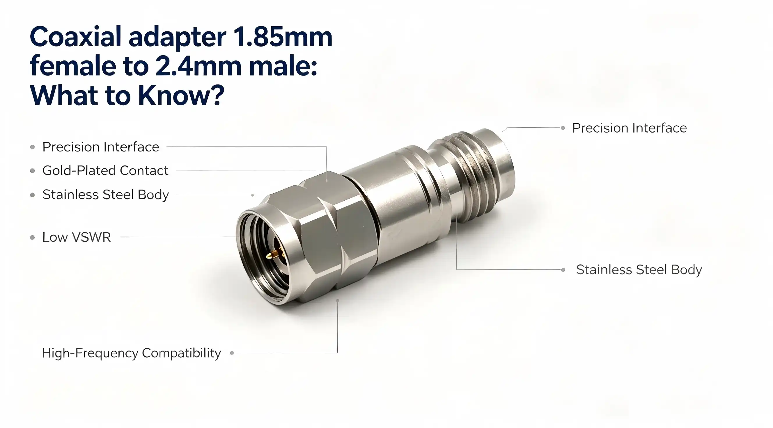
A coaxial adapter 1.85mm female to 2.4mm male is a precise cross-series interface converter for the connection of two different millimeter-wave connector standards in a single RF transmission line. One end has a 1.85mm female socket, the other a 2.4mm male pin. This allows the signal to be relayed seamlessly across devices that can not otherwise mate directly. Engineers use the adapter in 5G testing, satellite communications, or semiconductor validation to get around interface incompatibilities without having to redo complete test rigs. It is important to know how it is constructed, what its performance limitations are, and how it has to be handled before it can be used in any high-frequency measurement chain.

Understanding the 1.85mm to 2.4mm Coaxial Adapter
The 1.85mm and 2.4mm connection series are both precise RF connectors for millimeter wave operation, but are not technically compatible with each other. The 1.85mm interface supports frequencies up to 67 GHz, while the 2.4mm interface supports up to 50 GHz. This means a 1.85mm female to 2.4mm male adapter works reliably from DC to 50 GHz, limited by the lower-ceiling 2.4mm end. This is a huge difference in test situations where exceeding the rated frequency leads to reflections, higher VSWR, and less accurate measurements.
Cross-Series Design Mechanics
The interface conversion of the adapter is performed by a cross-series mechanical design. The female side of the 1.85mm has an internal socket for the male pin of instruments such as vector network analyzers (VNA). The male side of the 2.4mm has a precise center pin for mating with 2.4mm devices under test. This bidirectional transmission channel offers a consistent 50Ω impedance throughout the entire frequency range, which is essential to sustaining signal integrity at millimeter-wave frequencies.
Material Construction and Plating
Material choice directly influences the signal quality and service life. The exterior conductor is made of passivated stainless steel, which has good mechanical strength and corrosion resistance in different situations. The inner conductor is beryllium copper with a gold plating. This combination was selected for its low electrical resistance and resistance to oxidation, which are necessary for low-loss transmission over 30 GHz. The dielectric cavity is filled with PTFE (polytetrafluoroethylene), which has steady dielectric characteristics and guarantees a uniform 50Ω impedance match throughout the whole working range.
Technical Comparison and Performance Evaluation
If you are confused between 1.85mm female to 2.4mm male and vice versa, 2.4mm female to 1.85mm male, the directionality will only depend on the kind of interface port on your test equipment. A Coaxial adapter 1.85mm female to 2.4mm male should be selected based on the matching requirements of the connection. Changing the orientation of the adapter does not in itself affect the electrical performance, but it must be consistent with the mating connection gender on both the instrument and the item under test. Using the incorrect direction requires a double-adapter work-around that increases insertion loss and reflection.
Key Performance Specifications
The specs below describe the operational envelope of a properly made 1.85 mm to 2.4 mm millimeter wave adapter:
- Operating Frequency: DC to 50 GHz covers the whole 5G mmWave range (24-40 GHz) plus a considerable portion of satellite communication bands.
- VSWR: =1.35 over the whole rated frequency range, very low signal reflection and good impedance matching integrity.
- Insertion Loss: Consistently low throughout temperature fluctuations – a fundamental distinction between precision grade and commercial grade adapters.
- Connection torque: 0.8-1.1 Nm on 1.85 mm end. 0.5-0.8 Nm on 2.4 mm end. These torque levels are not recommendations – straying from them risks connection damage and irreversible performance deterioration.
- Mechanical endurance: ≥500 mating cycles, suitable for normal lab usage with no accelerated wear.
These specs put the 1.85mm to 2.4mm coaxial adapter firmly within the precision instrument grade class. Manufacturers such as Pasternack, Rosenberger, and Amphenol publish similar specs for their own versions, and these benchmarks should be used by procurement teams when assessing alternative vendors to ensure consistent performance.
How to Choose the Right 1.85mm to 2.4mm Coaxial Adapter
The choice of a millimeter-wave adapter is not only a matter of matching series and gender. The right decision depends on operational conditions, signal frequency, and long-term usage habits.
Align Specifications With Your Application
Check the exact working frequency limit of your system before you buy. If your test bench is working at or below 50 GHz, the coaxial adapter 1.85mm female to 2.4mm male configuration is entirely suitable. This is relevant for 5G base station testing, phased array radar characterisation, and satellite link testing. The low insertion loss of this adapter is particularly valuable for semiconductor RF development laboratories that are evaluating chip-level performance to 40 GHz. Small measurement mistakes at the component level might result in substantial disparities at the system level.
Evaluate Durability and Environmental Suitability
Test conditions are frequently high-frequency connect-disconnect cycles with occasional dampness or mild chemical contaminants. The core conductor of gold-plated beryllium copper prevents oxidation, and the passivated stainless steel body of the Coaxial adapter 1.85mm female to 2.4mm male withstands mechanical stress without galling. For laboratories where temperature swings occur, storage settings of -10°C to 40°C with humidity ≤60% RH are specified—and should be maintained to protect connection geometry and plating integrity.
OEM and Bulk Procurement Considerations
OEM manufacturers and system integrators purchasing bulk quantities of adapters should choose providers who offer bespoke interface requirements, consistent lot traceability and quick technical assistance. Buying in bulk lowers the cost per unit and lead time to receive the purchase. But only if the supplier has established quality control measures. As always, getting sample units before committing to a big purchase is good insurance, particularly if you’re working with an unknown connector series in an existing test chain.
Procurement and Supplier Guide for 1.85mm to 2.4mm Adapters
It is best to buy a precise 1.85mm female to 2.4mm male adapter from an authorized distributor or directly from the manufacturer instead of unauthorized secondary markets that may sell counterfeit or low-quality devices. R&D institutes and military contractors cannot afford signal measurement inaccuracies due to a low-cost copycat adaptor.
Chuangyu (Shaanxi Chuangyu Electronic Technology Co., Ltd.) produces precision RF connectors, millimeter-wave cable assemblies, and microwave components from its manufacturing base in Xi'an, China. Chuangyu, with over two decades of process know-how, a 500,000 RF components yearly production capability, and product lines from DC to 110 GHz, works with clients in the military, medical, telecommunications, semiconductor, and new energy industries.
Chuangyu coaxial adapter 1.85mm female to 2.4mm male is one of the main products of Chuangyu, produced according to international standards, with complete lot traceability and direct technical assistance. When considering any 1.85mm to 2.4mm adapter provider, look for their quality management certifications, internal testing capabilities (including VSWR and insertion loss verification), and their recorded mating cycle test results. Ensuring that delivery dependability and post-sale support – such as replacement policies and application engineering consultation – are in place is just as crucial to keeping project schedules unbroken.
Conclusion
The 1.85mm female to 2.4mm male coaxial adapter answers a very specific, recurrent issue in millimeter-wave test and measurement: two competent instruments that can not communicate without a trusted middleman. This adapter is constructed of gold-plated beryllium copper with a PTFE dielectric and passivated stainless steel. This 1.85mm female to 2.4mm male coaxial adapter is rated for VSWR ≤1.35 and always functions well across the frequency range of DC to 50 GHz with over 500 mating cycles. Whether the application is 5G protocol testing, semiconductor RF validation, or aerospace radar characterization, adequate torque application, pre-use inspection, and proper storage will go a long way toward extending service life. Select an adapter with published and confirmed specs, a manufacturer that gives traceability, and a support staff that can respond to technical issues before and after the sale.
FAQ
What cables are compatible with 1.85mm and 2.4mm connectors?
Both 1.85mm and 2.4mm connectors use precision coaxial cables designed for millimeter-wave frequencies. Common cable types include semi-rigid and phase-stable flexible assemblies with low-loss dielectric cores. When building a test chain incorporating a 1.85mm female to 2.4mm male adapter, confirm that the cable assemblies on both ends are rated to at least 50 GHz to avoid creating a bottleneck that degrades system-level VSWR.
Is this adapter suitable for 5G mmWave testing?
Yes. The 5G mmWave spectrum occupies 24–40 GHz, well within the DC–50 GHz operating range of a properly manufactured coaxial adapter 1.85mm female to 2.4mm male. Its low insertion loss and VSWR ≤1.35 make it appropriate for use with VNAs, spectrum analyzers, and signal generators in 5G base station and device testing environments.
How does insertion loss affect RF system performance?
Every decibel of insertion loss at the adapter level reduces the signal level reaching the measurement instrument. In millimeter-wave systems where signal margins are already tight, cumulative losses across multiple adapters and cables can distort measurement results. Precision-grade adapters minimize this loss, protecting the integrity of high-frequency characterization data.
Partner With Chuangyu for Precision RF Connectivity
Chuangyu delivers verified coaxial adapter 1.85mm female to 2.4mm male solutions backed by nearly two decades of RF manufacturing expertise, international-standard quality control, and an annual production capacity of 500,000 RF components. As a trusted coaxial adapter 1.85mm female to 2.4mm male manufacturer, we support OEM, ODM, and custom orders across defense, semiconductor, and 5G sectors. Visit cymicrowave.com to explore the full catalog, or reach our engineering team directly at chuangyuwz01@cymicrowave.com to request samples or a bulk order quote.
References
1. Pozar, D. M. Microwave Engineering, 4th ed. Wiley, 2011.
2. IEEE Standard 287-2007. IEEE Standard for Precision Coaxial Connectors (DC to 110 GHz). IEEE, 2007.
3. Marks, R. B., & Williams, D. F. "Characteristic Impedance Determination Using Propagation Constant Measurement." IEEE Microwave and Guided Wave Letters, 1991.
4. Dunsmore, J. P. Handbook of Microwave Component Measurements. Wiley, 2012.
5. 3GPP TS 38.101-2. NR; User Equipment (UE) Radio Transmission and Reception; Part 2: Range 2 Standalone. 3GPP, 2023.
6. Engen, G. F., & Hoer, C. A. "Thru-Reflect-Line: An Improved Technique for Calibrating the Dual Six-Port Automatic Network Analyzer." IEEE Transactions on Microwave Theory and Techniques, 1979.
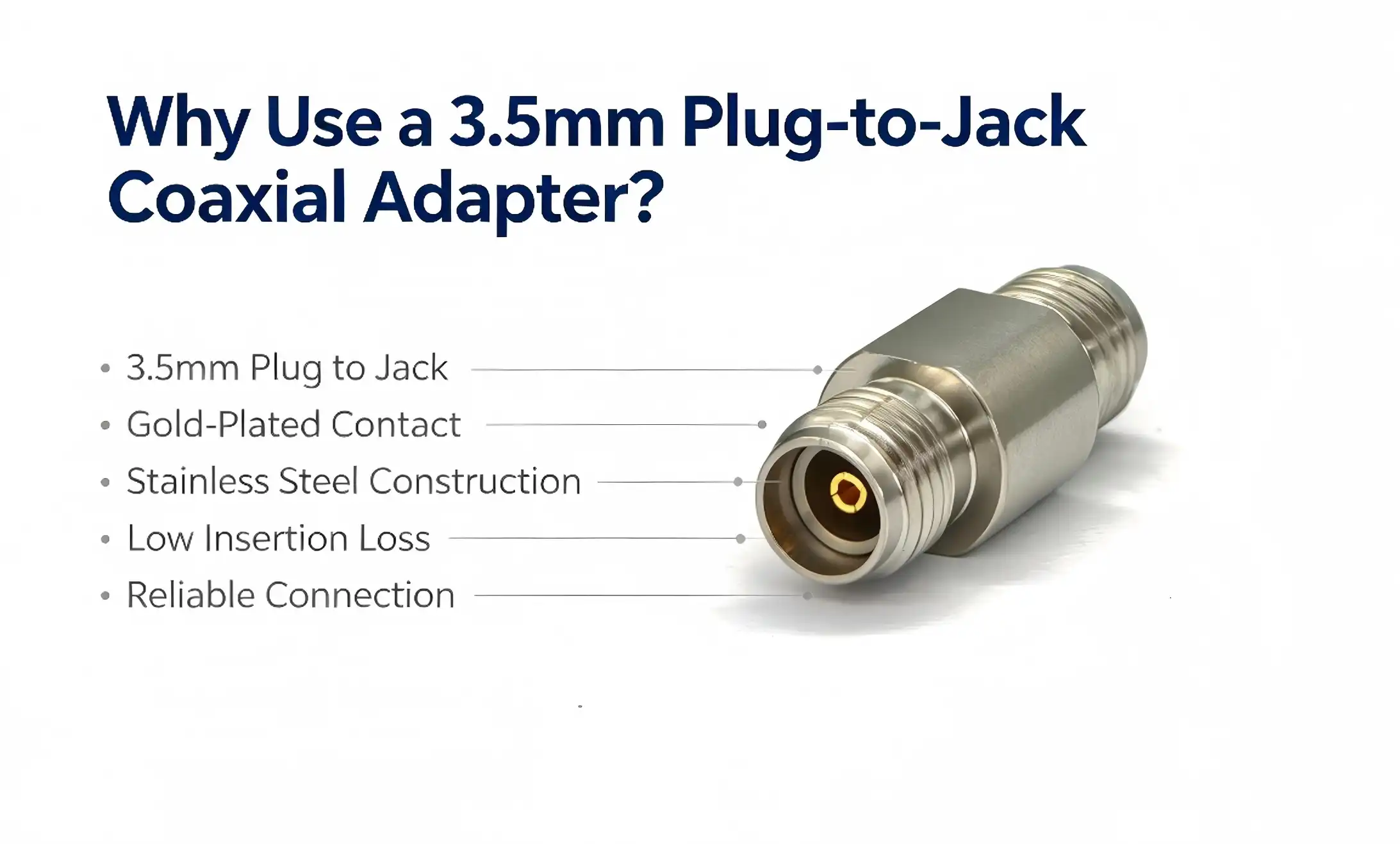
For dependable conversion between RF ports of opposite gender without signal loss when your test bench needs it, a coaxial adapter 3.5mm plug to 3.5mm jack is the precise tool bridging the gap. The component provides 50Ω characteristic impedance from DC to 26.5GHz, maintaining a VSWR of 1.35 or less, unlike common barrel adapters. Whether an R&D engineer testing 5G modules, a hardware designer integrating RF test equipment, or a procurement manager obtaining dependable microwave interconnects, this adapter provides traceable, verifiable performance — not just physical connection. Choosing the correct 3.5mm RF adapter influences the precision of your measurements, the repeatability of your system, and the long-term durability of your test fixture.

Understanding the 3.5mm Plug-to-Jack Coaxial Adapter
What Makes This Adapter Different from Standard Connectors
The 3.5mm plug-to-jack coaxial adapter is not an audio part. It is a precise RF connection for microwave signal transfer. Its coaxial topology of center conductor, dielectric, and outer conductor keeps the signals intact in ways that traditional two-conductor connections just can’t. Structurally, this adapter is a 50Ω impedance-matched coaxial design. The central conductor is gold-plated beryllium copper for superior conductivity and oxidation resistance. The insulating dielectric is PTFE, selected for its low dielectric loss at high frequencies. The outside conductor is made of stainless steel, providing both electromagnetic shielding and mechanical strength.
Gender Conversion and Interface Compatibility
One end of the adapter has a 3.5mm male connection with exposed pins; the other end has a 3.5mm female connector with an internal socket. This jack-to-plug arrangement overcomes a typical problem in RF test setups: polarity mismatch between instruments and devices under test. This 3.5mm RF adapter instantly addresses the clash when a vector network analyzer port and an RF module both provide the same gender interface – with no extra wiring.
Key Benefits of Using a 3.5mm Plug-to-Jack Coaxial Adapter
Engineers in semiconductor testing, 5G development, and microwave system integration cite three consistently performance-critical benefits when using this Coaxial adapter 3.5mm plug to 3.5mm jack in their settings. The main benefits of this component are:
- Verified high-frequency performance from DC to 26.5GHz with VSWR ≤1.35 and minimal Insertion loss. This level of reflection control translates directly into reducing measurement uncertainty in 5G NR sub-6GHz and mmWave FR2 test scenarios. That means a lot for calibration chains in spectrum analyzers and network analyzers.
- Mechanical durability for frequent use: The stainless steel exterior conductor resists corrosion and deformation during intensive laboratory cycles. The mating cycle value of ≥500 insertions suggests that this adapter is suitable for high-throughput semiconductor test applications where daily reconnection is common. Center pin retention force is set to ensure contact integrity without wear of the connection.
- Flexibility of the system without adding complexity: The 3.5mm coaxial interface is mechanically compatible with 2.92mm (K-connector) interfaces; therefore, this adapter may be smoothly added to mixed-connector test systems. A single kind of adapter may be used for many instrument ports, reducing inventory and simplifying spare-parts management.
These benefits make the 3.5mm plug-to-jack converter a high-value, low-risk procurement solution for RF research laboratories and production test floors.
Selecting the Best Coaxial Adapter for Your Business Needs
Key Procurement Criteria for RF Adapters
Don’t only look at the frequency range when choosing a 3.5mm RF coaxial adapter. Procurement managers and test engineers need to examine impedance uniformity throughout the whole frequency range, the quality of plating on the center pin, the grade of the outside conductor material, and the rated mating cycles. Suppliers who offer traceable test data, such as S-parameter files, VSWR curves, and torque parameters, show the technical discipline required for high-reliability applications. Buying in bulk from a vertically integrated producer lowers cost per unit and ensures lot-to-lot uniformity. Some manufacturers are also able to provide custom configurations, including other plating possibilities or adjusted torque parameters, if they are able to do their own machining and plating.
Why Material Choices Affect Long-Term Cost
Beryllium copper center pins provide better retention force stability over several mating cycles than brass. PTFE dielectric provides dimensional stability at severe temperatures, a critical need for aerospace and military applications that undergo thermal cycling as part of their certification. The stainless steel exterior conductors are far more resistant to corrosion in humid laboratory settings than passivated brass. A good source of a coaxial adapter 3.5mm plug to 3.5mm jack would be transparent about the materials used, which is a good practical indication of quality.

How to Use and Troubleshoot a 3.5mm Plug-to-Jack Coaxial Adapter
Pre-Use Inspection and Proper Installation
Inspect the outside conductor for any deformation. Inspect the gold plating on the center pin for any oxidation or physical damage. Then attach a 3.5 mm plug-to-jack RF adapter. Replace any adapters that show noticeable wear immediately. A compromised adapter may generate impedance discontinuities that will contaminate the measurement results. During installation, ensure the interface is correctly aligned before engagement. Tighten to the value provided by the manufacturer using a calibrated torque wrench, usually ≤0.5 N·m. Oblique insertion or over-tightening may cause irreparable structural damage to the adapter and the mating port of costly test equipment.
Signal Control and Troubleshooting
The test signal frequency should be in the range DC to 26.5GHz. Outside this range, performance drops unexpectedly. Measurement baselines may be affected by external electromagnetic interference; hence, high-frequency testing should be done in a protected container. If you see an unexpected spike in VSWR measurements or an increase in signal attenuation without any clear explanation, examine the mating connection first, since partial engagement is a frequent cause. If reseating the connection does not correct the anomaly, examine the adapter for mechanical wear. Do not leave a bad 3.5mm coaxial RF adapter in the signal path during active testing.
Maintenance and Storage Best Practices
Clean the interface using specialist RF cleaning swabs wetted with anhydrous alcohol. Store the Coaxial adapter 3.5mm plug to 3.5mm jack in a sealed container, without corrosive gas, dry, at a temperature from -10°C to 40°C and humidity ≤60% RH. Regular maintenance extends the service life much beyond the authorized 500 mating cycles and maintains calibration traceability.
Application Fields for the 3.5mm Plug-to-Jack Adapter
The 3.5mm Male to Female RF Adapter is used in a variety of precision-critical industries:
- Microwave communication testing: The adapter offers interface conversion between vector network analyzers, spectrum analyzers, and the device under test during 5G base station validation and RF module characterisation while guaranteeing signal route integrity throughout the measurement chain.
- Semiconductor RF development: Engineers often encounter instrument ports and device test sockets with the same connection gender while testing RF chips and microwave ICs. This 3.5mm coaxial adapter addresses the mismatch without generating any substantial electrical discontinuity.
- Aerospace and Defense: Military radar and electronic warfare systems need RF interconnects that can fulfill demanding environmental and reliability requirements. The stainless steel outer conductor and beryllium copper core pin of this adaptor do.
- Test System integration: RF test setups generally need polarity-matched extension ports. 3.5mm plug to 3.5mm jack adaptor reduces interface polarity issues and improves fixture adaptability.
Conclusion
A 3.5 mm plug to 3.5 mm jack precision Coaxial adapter 3.5mm plug to 3.5mm jack is a modest item that may have a big impact on the accuracy of measurements and the durability of the system. Its 50Ω coaxial construction, PTFE dielectric, beryllium copper center pin, and stainless steel outer conductor all cooperate to guarantee signal integrity from DC to 26.5GHz. When you purchase the proper 3.5mm RF adapter from a company you trust, you’ll get excellent measurements and longer equipment life. This is true whether you use it for 5G validation, semiconductor characterization, aircraft RF inspection, or test fixture integration.
FAQ
What is the maximum operating frequency of a 3.5mm plug-to-jack coaxial adapter?
The standard 3.5mm coaxial adapter operates from DC to 26.5GHz, making it suitable for 5G sub-6GHz testing, microwave component characterization, and vector network analyzer work within that frequency band.
Is a 3.5mm RF adapter compatible with 2.92mm connectors?
The 3.5mm interface is mechanically compatible with 2.92mm connectors, allowing mixed-connector test configurations without additional adapters in many setups.
How many mating cycles can I expect from this adapter?
Quality 3.5mm plug-to-jack RF adapters are rated at ≥500 mating cycles. Proper torque application and regular cleaning extend operational life beyond that baseline.
What torque should I use when connecting a 3.5mm RF adapter?
Apply ≤0.5 N·m using a calibrated torque wrench. Exceeding this value risks damaging the adapter and the mating instrument port.
How do I know when to replace a 3.5mm coaxial adapter?
Replace the adapter immediately if VSWR increases unexpectedly, if insertion loss rises abnormally, or if physical inspection reveals pin damage, deformation, or coating degradation.
Partner with Chuangyu for Reliable 3.5mm RF Adapter Solutions
Chuangyu supplies precision coaxial adapter 3.5mm plug to 3.5mm jack components built to international RF standards, with traceable performance data and an annual production capacity exceeding 500,000 RF components. As a trusted coaxial adapter 3.5mm plug to 3.5mm jack manufacturer, Chuangyu supports OEM customization, bulk procurement, and rapid order fulfillment from its Xi'an facility. Contact the technical team directly at chuangyuwz01@cymicrowave.com or visit cymicrowave.com to request specifications, samples, or a procurement quotation.
References
1. Pozar, D. M. — Microwave Engineering, 4th Edition, Wiley, 2011.
2. IEEE Std 287-2007 — IEEE Standard for Precision Coaxial Connectors (DC to 110 GHz), IEEE, 2007.
3. Hirose, K. — "Electrical Performance of Precision RF Coaxial Connectors for Microwave Test Systems," IEICE Transactions on Electronics, 2018.
4. Dunsmore, J. P. — Handbook of Microwave Component Measurements, Wiley, 2012.
5. Laverghetta, T. S. — Practical Microwaves, Prentice Hall, 1996.
6. MIL-PRF-39012G — General Specification for Connectors, Coaxial, Radio Frequency, U.S. Department of Defense, 2020.
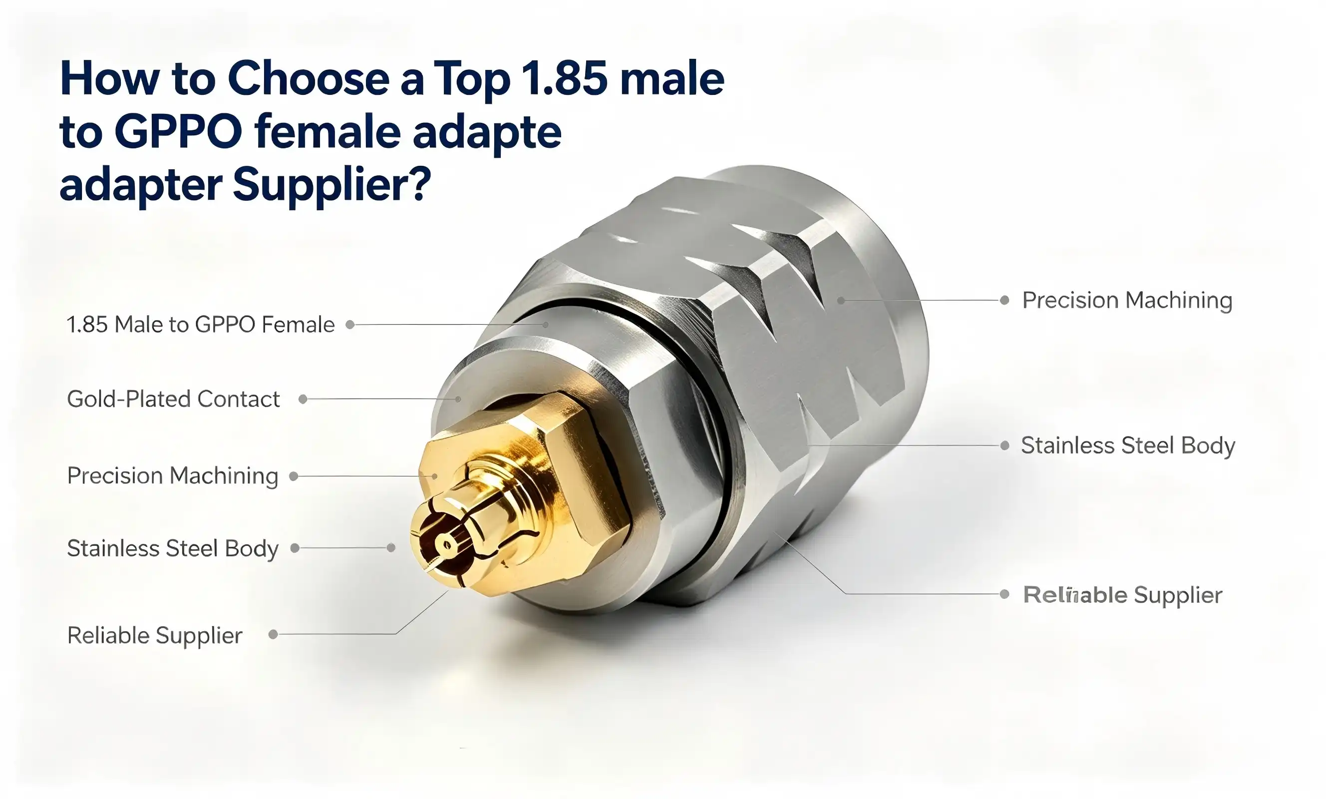
The correct 1.85 male to GPPO female adapter provider makes the difference between your millimeter-wave test equipment performing at its maximum and expensive signal deterioration. With the operating frequency extending into the DC-67 GHz region for 5G/6G and phased-array radar and semiconductor wafer-level testing, even a little reduction in the quality of the connection may distort measurement accuracy and jeopardize project timetables. This document provides the technical basics, the assessment criteria for suppliers, and procurement techniques that procurement managers, R&D engineers, and hardware design engineers need to have to be able to confidently find a dependable 1.85 mm to GPPO (SSMP) adapter.

Understanding the 1.85 Male to GPPO Female Adapter and Its Market Requirements
What This Adapter Actually Does
1.85 male to GPPO female adapter is a cross-series RF interface converter. One end is terminated with a 1.85 mm male connection, the millimeter-wave standard interface used in vector network analyzers and spectrum analyzers. The other end is terminated with a GPPO (SSMP) female connector, an ultra-small millimeter-wave interface which is frequently integrated in tiny RF modules and test boards. They combine to provide signal relay between 1.85 mm transmitting equipment and GPPO reception devices of various millimeter wave product families.
Technical Specifications That Define Performance
For a high quality 1.85 mm to GPPO adapter, the right choice of materials is dependent on the strength of the structure. The exterior conductor is stainless steel passivated for both mechanical strength and corrosion resistance. The inner conductor is made of gold-plated beryllium copper to reduce resistive loss at high frequencies. PTFE is the dielectric material, providing reliable 50 Ω impedance matching from DC to 67 GHz. The VSWR is under 1.35, and insertion loss is minimal throughout the whole band, which is crucial for reliable millimeter-wave signal transmission. The 1.85 mm threaded end has a connection torque of 0.8-1.1 Nm. The GPPO push-in end has a radial offset of ≤±0.25 mm and an axial tolerance of ≤+0.25 mm, with an insertion/extraction life of ≥500 cycles. They are not random. Any adapter that is even slightly out of impedance specifications will create reflections that will corrupt S-parameter measurements. That’s a risk no semiconductor R&D team or military contractor can afford to take.
Core Criteria to Evaluate When Choosing a 1.85 Male to GPPO Female Adapter Supplier
Define Your Procurement Baseline
Before reaching out to any 1.85 to GPPO adapter manufacturer, be sure to define your project’s non-negotiable requirements: frequency band, order volume, customisation demands, lead time, compliance criteria. Buyers of 5G base station MIMO antenna arrays confront different limitations than those producing phased-array radar test benches. For applications requiring precise RF connections, a 1.85 male to GPPO female adapter should also be evaluated based on compatibility, performance stability, and manufacturing quality. These are the main assessment criteria that a competent provider must meet:
- Certifications and compliance: The baseline is quality management ISO 9001 and RoHS environmental compliance. For suppliers supplying to aerospace or military industries, suppliers should additionally show compliance with MIL-spec material and process requirements.
- Verified RF Performance Data: Search for traceable test reports with VSWR < 1.35, insertion loss curves over the DC-67 GHz span, and impedance consistency at 50 Ω. Generic datasheets without calibrated measurement data are a red flag.
- Customization capability: OEM and ODM maker needs always non-standard interface configurations or unique coatings. A competent provider of GPPO female adapters should be able to meet custom mechanical and electrical criteria.
- Lead time and logistical transparency. Global customers care as much about verified manufacturing lead times, foreign freight choices, and clear paperwork for customs clearance as they do about product requirements.
- Warranty coverage, technical support access, and a structured return/repair procedure guarantee your operational continuity should unforeseen problems happen.
In unison, these criteria provide a shortlist framework to filter out dubious sources before you spend money on samples.
Comparing Leading 1.85 Male to GPPO Female Adapter Suppliers and Brands
Global stalwarts in the millimeter-wave RF adapter industry include Rosenberger, Huber+Suhner, and Amphenol, as well as precision-focused Chinese producers like Chuangyu. There are trade-offs in price, customizability, agility, and lead time for each category.
Shaanxi Chuangyu Electronic Technology Co., Ltd. (Chuangyu) has been well-known for almost 20-year RF connector engineering. The millimeter-wave connector with a 110 GHz rating is at the top level in China and meets international requirements. It is this depth that is reflected in their 1.85 male-to-GPPO female adapter line: every unit combines passivated stainless steel housings, gold-plated beryllium copper center pins, and PTFE dielectrics built to precise dimensional specifications. The 1,000-square-meter dedicated RF component lines at the Xi'an manufacturing facility produce 500,000 RF components annually, allowing the company to satisfy large orders without sacrificing quality.
Upfront unit price is not the whole story for a cost-efficiency study. A 500 cycle insertion / extraction life, steady VSWR, and uniform gold plating on an adapter decreases replacement frequency and recalibration downtime – offering significantly better total cost of ownership than a cheaper part that wanders out of spec after 200 cycles.
How to Navigate Procurement and After-Sales Support for 1.85 Male to GPPO Female Adapters
Step-by-Step Procurement Workflow
A disciplined procurement process avoids expensive surprises. The procedure logically runs from technical inquiry to sample validation, manufacturing order, and post-delivery assistance for products such as the 1.85 male to GPPO female adapter.
- Ask and align specs: Give the supplier the complete technical specifications (frequency range, physical dimensions of mating interfaces, environmental requirements, quantity, etc.), and the supplier will verify if the product meets your needs or suggest revisions.
- Sample testing: Request pre-production samples and test VSWR, insertion loss, and mechanical fit with the actual interface geometry of your test system. Objective data using a calibrated VNA
- Order confirmation and personalization: Complete designs, surface finish standards, labeling and packing. For OEM customers, ensure that tooling and NDA terms are recorded before manufacturing starts.
- Logistics coordination: International customers should confirm Incoterms, method of freight, and HS code classification early to minimize customs delays that increase effective lead times.
Protecting Your Investment Through After-Sales Support
A GPPO SSMP adapter manufacturer will provide you with explicit warranty conditions to guarantee the quality of their goods. Communicate pre-use inspection methods – looking for distorted exterior conductors, plating that is flaking, or oxidized connections. If there is an abrupt increase in VSWR or an anomalous attenuation of signals during testing, the provider should offer quick diagnostic help. Cleaning guidelines (RF swabs with anhydrous alcohol, storage at -10 °C to 40 °C, humidity ≤60% RH) and established fault escalation procedure ensure both component life and test integrity.
Summary: Making the Final Choice and Ensuring Long-Term Supplier Satisfaction
Choosing the right provider for your application requires honest alignment of technical standards with commercial goals. A team deploying 1.85 mm to GPPO adapters for semiconductor wafer-level testing requires different tolerances and a different level of customisation than a military contractor qualifying electronic warfare modules – but both need uncompromising signal quality up to 67 GHz. When sourcing a 1.85 male to GPPO female adapter, engineers should also evaluate compatibility, manufacturing precision, and long-term reliability to ensure stable performance in demanding RF applications.
The best supplier partnerships occur when both sides see quality evaluation as a continual process, not a one-time gate. Regular performance assessments, open communication channels for specification changes, and the flexibility to negotiate variable order quantities will let the collaboration grow with your engineering needs. Choose providers that are willing to disclose manufacturing data proactively, are open to audits, and are invested in your application results.
FAQ
How do I verify that a 1.85 male to GPPO female adapter is compatible with my test system?
Check the adapter's impedance (50 Ω), frequency rating (DC–67 GHz), and mechanical tolerances against your instrument's interface specifications. Request calibrated VNA test reports from the supplier and run a bench-level verification using your actual test setup before committing to volume orders.
What certifications should I require from a millimeter-wave adapter supplier?
ISO 9001 quality management certification and RoHS compliance are the minimum. Defense and aerospace procurement may additionally require MIL-spec material traceability and environmental stress test documentation.
Can suppliers support custom configurations for non-standard interfaces?
Yes. Established manufacturers like Chuangyu offer OEM and ODM customization covering interface geometry, surface coatings, and dimensional modifications. Submit detailed engineering drawings with your inquiry to accelerate feasibility assessment.
What causes sudden VSWR increases during use?
Common causes include improper torque on the 1.85 mm threaded end (outside the 0.8–1.1 Nm range), misaligned GPPO push-in connection, oxidized contact surfaces, or mechanical wear from repeated cycling beyond the rated 500 insertions.
How should I store these adapters to maximize service life?
Store in a sealed, dry container free of corrosive gases. Maintain ambient temperature between −10 °C and 40 °C and relative humidity at or below 60% RH. Clean interfaces with RF-grade swabs and anhydrous alcohol before storage.

Partner with Chuangyu for Precision 1.85 Male to GPPO Female Adapters
Chuangyu delivers industry-proven 1.85 male to GPPO female adapter solutions engineered for DC–67 GHz millimeter-wave performance. As a trusted 1.85 male to GPPO female adapter manufacturer, we support OEM customization, rapid sampling, and bulk fulfillment backed by ISO-compliant quality control. Visit cymicrowave.com or contact our engineering team directly at chuangyuwz01@cymicrowave.com to request samples or discuss your specific RF application requirements today.
References
1. Pozar, D. M. Microwave Engineering, 4th ed. Wiley, 2011.
2. IEEE Transactions on Microwave Theory and Techniques, IEEE, 2023.
3. Engen, G. F. & Hoer, C. A. "Thru-Reflect-Line: An Improved Technique for Calibrating the Dual Six-Port Automatic Network Analyzer." IEEE Transactions on Microwave Theory and Techniques, 1979.
4. IPC-A-620: Requirements and Acceptance for Cable and Wire Harness Assemblies, IPC, 2022.
5. MIL-STD-348B: Interface Standard for RF Connector Interfaces for MIL-PRF-39012 Connectors, U.S. Department of Defense, 2017.
6. Global RF Connectors Market Report, MarketsandMarkets Research, 2024.
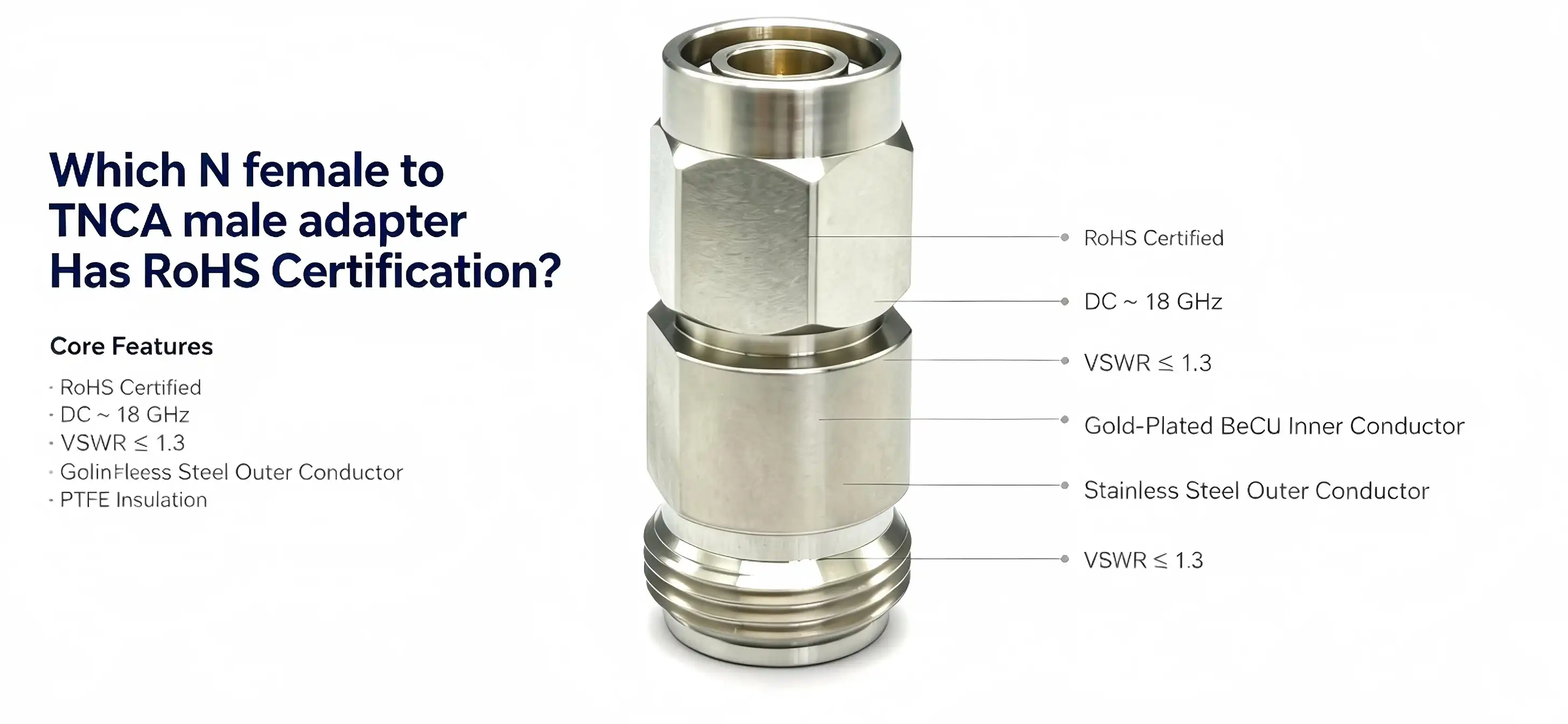
If you are looking for a compatible RF adapter for use in industrial or laboratory environments, the quick answer is: RoHS-compliant N female to TNC. There are male adapters, and choosing the proper one is so much more than checking a box. Chuangyu’s N female to TNCA male adapter is RoHS certified and has a gold-plated beryllium copper inner conductor, a passivated stainless steel outer conductor and PTFE insulation, all of which are free of lead, mercury, cadmium or other banned elements. It is a proven solution for test engineers and procurement teams requiring regulatory compliance and demonstrable signal performance, operating from DC to 18 GHz with a VSWR of 1.3 or below.

Technical Overview: N Female to TNCA Male Adapter Specifications
N female to TNCA male Adapter combines two different thread standards in one precision-machined body. An understanding of its structure shows that the choice of materials has a direct effect on compliance and RF performance. The N female end has a 5/8-24UNEF threaded outer conductor manufactured from brass and plated with nickel or gold. Its elastic socket inner conductor mates with the N male pin with a suggested torque of 0.8–1.2 N·m, providing vibration-resistant mechanical stability. The TNCA male end is an extended-frequency derivation of the TNC standard with comparable interface dimensions and has a passivated stainless steel outer conductor with a 7/16-28UNEF threaded fitting and a stiff pin of beryllium copper with a gold plate. The resistance at the TNCA male interface is generally less than or equal to 2 mΩ.
Core Electrical and Mechanical Performance Parameters
The PTFE or PEI core insulator of the adapter provides consistent 50 Ω impedance from DC to 18 GHz. The following are the proven performance metrics that procurement engineers need to compare against competitor products:
- Frequency Range: DC to 18 GHz, for millimeter wave testing and satellite communication signal chains
- VSWR: ≤1.3 across the entire working range, reducing signal reflection in high-sensitivity measuring systems
- Contact resistance: 2 mΩ max at inner conductor contact for reduced insertion loss
- Mechanical cycle life ≥ 500 mating/unmating cycles MIL-STD-202 vibration test conditions
- Operating torque (male TNCA end): 0.5 to 0.8 N. m to safeguard the precise thread structure
The specifications make the N female to TNCA male adapter an effective interface for network analyzers, signal generators, radar front-ends, and aircraft avionics, or any place where signal quality and mechanical endurance must co-exist. Together, these specs prove that a fully RoHS certified adapter does not lose performance for compliance. The gold-plated beryllium copper center conductor and PTFE dielectric meet the RoHS material limits and provide the conductivity and dielectric stability needed by high frequency RF systems.
How to Identify RoHS-Certified N Female to TNCA Male Adapters in the Market
Verifying Authentic RoHS Documentation
True RoHS compliance means the manufacturer has produced a Declaration of Conformity referencing the particular version of the Directive (2011/65/EU or the 2015/863/EU amendment) and has supporting material testing results (ICP-MS or XRF). When purchasing any N female to TNCA male adapter source, ask for the whole material composition data, not just the product label. The internet catalogs of reputable manufacturers such as Amphenol, Pasternack, and Rosenberger include RoHS status per SKU that procurement teams may cross-check against internal compliance databases.A typical misperception is that a “RoHS compliant” logo on a product bears the same legal weight as a Declaration of Conformity supported by test evidence. It does not do. Unsubstantiated or false claims are common on third-party reseller platforms; thus, requesting direct supplier documentation is a must-have step in the certification process.
Comparing RoHS-Certified Coaxial Adapters: What Differentiates Quality Suppliers
Not all RoHS compliant N to TNCA adapters are created equal, and selection should be based on more than the compliance label. The difference between certified suppliers is related to material traceability, dimensional tolerance, and post-sale technical assistance. The Chuangyu adaptor line illustrates how RoHS compliance fits with precision production. The passivated stainless steel TNCA male outer conductor is immune to corrosion in humid or chemically active situations – a significant benefit in industrial automation and aeronautical maintenance bays. The inner conductor is gold-plated beryllium copper, to a RoHS compliant thickness, to provide minimal contact resistance during the whole 500-cycle mechanical life. So a supplier selling a product with generic brass pins who doesn't know and control the plating material used can say they are RoHS but not have the material controls to back it up. Supplier evaluation criteria for 2024 N female to TNCA male adapter:
- Depth of documentation: Full Declaration of Conformity and material test results, not just a label
- Connector body tolerance: Precision machined to IEC 61169 dimensional specifications to provide repeatable mating force and thread engagement
- availability and lead time: High-volume buying, however, is better served by suppliers with specialized manufacturing lines, rather than catalog resellers
- Custom/OEM capability: Test-house and system integrator customers typically demand customized flange mounts, longer bodies, or non-standard plating – direct manufacturers fill those requirements where distributors cannot
Such criteria enable procurement managers to go beyond checking compliance at a superficial level and instead establish a supplier relationship based on demonstrable quality. Unit pricing is as important as supplier dependability and audit readiness to OEM and ODM customers with complicated supply chains.
Best Practices for Procuring RoHS-Certified RF Adapters
The first step to the successful purchase of certified RF connectors is to distinguish between catalog claims and verified proof. Before you place a purchase order, you need to have third-party RoHS test results and make sure that the frequency rating, impedance, and connector interface dimensions of the adapter meet your system requirements. The product datasheet should provide mechanical durability criteria for applications from satellite ground stations to industrial millimeter-wave inspection systems to aerial navigation equipment, and in particular, MIL-STD-202 vibration compliance, not only stated orally. Dealing directly with the manufacturer instead of the middleman distributor shortens the paperwork chain and makes OEM customization requests simpler. While platforms like Amazon Business work well for low-volume spot buys, volume purchasers and test institutes are better served via negotiated supplier relationships that involve quality audits, sample qualification runs, and documented change control for material replacements.
Conclusion
The RoHS certification on an N female to TNCA male adapter may be verified and is technically and procurement significant. Rigorous material selection – gold-plated beryllium copper conductors, PTFE insulators, passivated stainless steel housings – that meets hazardous substance limitations and provides dependable DC–18 GHz RF performance supports the certification. Those customers who need comprehensive Declaration of Conformity documents, check material test results, and evaluate supplier manufacturing depth will always get adapters that work in the field and pass compliance audits. Chuangyu’s approved adapter range satisfies these criteria and offers bespoke configurations for demanding industrial and aerospace applications.
FAQ
How quickly can I verify RoHS certification for an N female to TNCA male adapter?
Request the supplier's Declaration of Conformity referencing Directive 2011/65/EU alongside the ICP-MS or XRF material analysis report. Established manufacturers maintain these documents per part number and can provide them within one business day.
Are certifications from brands like Amphenol or Pasternack more reliable than those from precision manufacturers?
Certification reliability depends on documentation depth and material testing protocols, not brand scale. Both large-catalog brands and specialized precision manufacturers like Chuangyu maintain auditable RoHS records. Verify the test report rather than relying on brand reputation alone.
What happens if I use a non-RoHS-compliant adapter in an industrial environment?
Non-compliant products risk customs seizure at EU and UK borders, contractual penalties from OEM clients with environmental mandates, and potential liability if hazardous material exposure occurs during maintenance. In regulated sectors such as medical devices and aerospace, non-compliance can trigger product recalls or contract terminations.
Can N female to TNCA male adapters be customized for OEM applications while retaining RoHS status?
Yes. Manufacturers with in-house machining and plating controls can modify body dimensions, add flange mounts, or adjust plating specifications while maintaining full RoHS compliance—provided the substitute materials remain within permitted substance thresholds.

Connect with Chuangyu for Certified N Female to TNCA Male Adapter Solutions
Chuangyu delivers precision-engineered, RoHS-certified RF coaxial adapters to OEM manufacturers, test institutions, and system integrators across the United States and globally. As a direct N-female-to-TNCA male adapter manufacturer with nearly two decades of RF component expertise, Chuangyu offers competitive pricing, documented compliance, and OEM customization. Reach out to our procurement specialists at chuangyuwz01@cymicrowave.com or visit cymicrowave.com to request a quote today.
References
1. European Parliament. Directive 2011/65/EU on the Restriction of the Use of Certain Hazardous Substances in Electrical and Electronic Equipment. Official Journal of the European Union, 2011.
2. IEC. IEC 61169-16: Radio-Frequency Connectors — Part 16: Sectional Specification for Type N Connectors. International Electrotechnical Commission, 2013.
3. MIL-STD-202H. Test Method Standard: Electronic and Electrical Component Parts. U.S. Department of Defense, 2015.
4. Amphenol RF. Product Compliance and RoHS Documentation Guide. Amphenol Corporation, 2022.
5. Pasternack Enterprises. RF Coaxial Adapter Technical Reference and Compliance Overview. Pasternack, 2023.
6. Rosenberger. RF Connectors and Adapters: Material Compliance and High-Frequency Performance Standards. Rosenberger Hochfrequenztechnik, 2021.
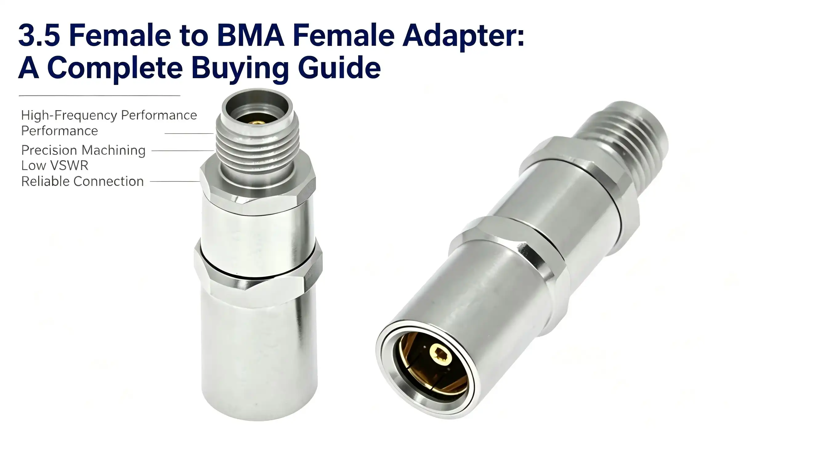
If you work in RF testing, microwave communication or high frequency system integration you have probably experienced interface compatibility problems with various connection types. This article will explain all you need to know about the 3.5 female to BMA female adapter including physical construction and materials, procurement strategy, installation and maintenance. Whether you're an R&D engineer considering your signal relaying alternatives or a procurement manager buying in volume, this resource will provide the technical clarity and practical knowledge needed to make informed buying decisions.

Understanding the 3.5 Female to BMA Female Adapter
What Makes This Adapter Unique?
The 3.5 female to BMA female adapter is a series to series coaxial interface converter. One end has a 3.5mm female connection, a precise microwave interface with an internal jack and the other end has a BMA female connector for blind mating. Combined, these two cover the two connection families and allow the signal to be sent between the 3.5mm and BMA devices without compromising the precision of the measurement.This adapter is characterized from DC to 18 GHz with a VSWR < 1.25, and a 50$\Omega$ characteristic impedance for the frequency range. These characteristics are directly relevant for vector network analyzers, spectrum analyzers, RF module test platforms.
Core Material and Construction
This adapter gets its structural stability from 3 carefully chosen materials. The exterior conductor is passivated stainless steel, providing corrosion resistance and mechanical robustness in severe laboratory or field settings. The inner conductor is gold plated beryllium copper which reduces resistive loss and allows for reliable high frequency signal transmission. PTFE (polytetrafluoroethylene) is used as the dielectric insulator and is well known for its low dielectric loss and dimensional stability, both of which are crucial to ensuring 50Ω impedance matching across the working range.The BMA end has a blind mating mechanism which allows for some misalignment during attachment and has a rated mating life of ≥500 cycles. The 3.5mm end must be installed with a regulated torque of 0.5-0.8 Nm using a calibrated torque wrench to minimize mechanical stress on the interface.
Comparing the 3.5 Female to BMA Female Adapter with Alternatives
3.5mm Female vs. SMA Female: Where the Difference Matters
Engineers often question whether a SMA-based adapter can replace a 3.5mm connection in high-frequency applications. The SMA connections have the same 50Ω impedance and the same approximate physical dimensions but the maximum frequency is usually 18 GHz in perfect circumstances . The 3.5 mm interface does keep the same electrical performance at that limit with more strict dimensional restrictions . The 3.5mm female interface offers more predictable return loss characteristics for applications requiring measurement precision better than 12 GHz.Comparison of the main performance metrics side by side:
- 3.5 female to BMA female adapter: DC-18 GHz, VSWR ≤1.25, inner conductor gold plated beryllium copper, body stainless steel, blind mating BMA end, ≥500 mating cycles.
- SMA female to BMA female adapter: DC–18 GHz (standard spec) VSWR ≤1.20 in high-spec versions Brass or stainless steel body PTFE dielectric MIL-STD-348 compatible
- SMA female to SMA female barrel adapter: DC-18 GHz, simpler mechanical design, no blind mating capability, more accessible at cheaper cost.
These characteristics help to explain where each adapter fits. The 3.5 female to BMA female adapter has a particular benefit over SMA barrel adapters in precision microwave testing conditions where it is operationally critical to blind mate.
How to Choose the Right 3.5 Female to BMA Female Adapter
Selecting the appropriate adaptor is both a technical and procurement choice that has downstream impact on system dependability, maintenance frequency and total cost of ownership. There are a few things to watch out for:
- Frequency ceiling: Make sure that your test signal is inside DC-18 GHz. If your application extends beyond this range you will need a whole other interface family.
- Mating environment: The BMA blind mating architecture is ideal for high density PCB backplane assembly and rack mounted test systems where manual alignment is not feasible.
- Mechanical durability: A service life rating of ≥500 cycles is acceptable in most laboratory conditions. This could be justified for high turnover ATE (automated test equipment) installations.
- Plating quality: Gold plated beryllium copper inner conductors provide reduced contact resistance and longer service life than ordinary brass connections.
- Supplier traceability: OEM and ODM firms may decrease qualification risk via procurement from suppliers with established quality management systems (including lot traceability and dimensional inspection records).
All these parameters are used to determine the appropriateness of your adapter. For procurement managers, working with large quantities, negotiating sample validation of the 3.5 female to BMA female adapter before full volume commitment ensures both technical and timetable integrity.
Installation, Troubleshooting, and Best Practices
Step-by-Step Installation and Signal Integrity Checks
The performance of the adapter to its rated specifications is directly affected by proper installation. Prior to mating visually check the outer conductor for distortion, the gold plating for peeling or oxidation and the female socket for debris or physical damage. Any evident flaw is grounds for prompt repair – utilizing a damaged adapter risks contaminating the device under test with reflection artifacts.When installing, use a calibrated torque wrench to impart precisely 0.5-0.8 Nm of torque to the 3.5 mm end. Undertorquing creates impedance discontinuities. Overtorquing threatens cold welding of the threads or deforming the inner conductor. Make that the interfaces are aligned on the BMA side before applying seating force – oblique insertion is a major cause of blind mating connection failure.
Maintenance, Cleaning, and Storage Protocols
Regular servicing prolongs service life and maintains measuring accuracy. After every 20 to 30 connections or soon after any suspected contamination, wipe the mating surfaces with a specialist RF cleaning swab wetted with anhydrous isopropyl alcohol. Store adapters in sealed, non-corrosive environment from -10 degrees C to +40 degrees C, relative humidity not to exceed 60% RH.If you see VSWR values jump abruptly or insertion loss climb over the rated baseline, detach the adapter and examine the mating contact with magnification. Do not continue testing with a questionable adapter -- poor contact geometry provides repeated measurement errors that may invalidate an entire characterisation data set.
Conclusion
The 3.5 female to BMA female adapter is a specialized, yet critical component in microwave test equipment. It offers a reliable interface conversion between two different connector types without degrading signal integrity. It runs throughout the DC–18 GHz frequency range, has a VSWR of ≤1.25, gold-plated beryllium copper contacts, and a stainless steel body, catering for the needs of RF engineers and procurement teams engaged in the fields of telecommunications, semiconductor testing, and industrial automation. Choosing the proper adapter involves matching technical parameters to your application needs and purchasing from providers with proven quality standards.
FAQ
Does this adapter support both analog and digital microwave signals?
The 3.5 female to BMA female adapter handles any signal type — analog or digital — transmitted within the DC–18 GHz operating range. Signal type is secondary to frequency content; what matters is that the spectral energy of your signal stays within the rated band.
Can I use this adapter with standard 50Ω coaxial cables?
The adapter is designed for 50Ω systems. It interfaces cleanly with standard semi-rigid and flexible coaxial cables terminated in 3.5mm male connectors on the instrument side, provided the cable's own characteristic impedance is 50Ω.
What affects lead time for bulk orders?
Lead times depend on order volume, plating specification, and whether custom dimensions or marking are required. Standard configurations typically ship within normal production cycles; customized variants require additional qualification time. Confirming specifications upfront — including torque requirements and environmental rating — shortens the procurement cycle.
Is the BMA end compatible with PCB-mounted BMA receptacles?
The BMA female end is designed for blind mating against BMA male pins or plug-type receptacles mounted on PCBs or chassis panels, accommodating minor radial and axial float typical of high-density board layouts.

Partner with Chuangyu for Your RF Connector Needs
Chuangyu supplies precision 3.5 female to BMA female adapters built to microwave-grade tolerances, with full material traceability and documented inspection records. As a trusted 3.5 female to BMA female adapter manufacturer serving RF communication, semiconductor testing, and industrial automation clients across the U.S. and globally, Chuangyu combines nearly two decades of connector engineering expertise with an annual production capacity of 500,000 RF components. Custom configurations, OEM support, and bulk order pricing are available. Reach out to our technical team at chuangyuwz01@cymicrowave.com or visit cymicrowave.com to request a quote.
References
1. IEEE Transactions on Microwave Theory and Techniques – IEEE, 2021
2. RF and Microwave Engineering: Fundamentals of Wireless Communications – Gustrau, F., Wiley, 2012
3. MIL-PRF-39012: General Specification for Connectors, Coaxial, Radio Frequency – U.S. Department of Defense, 2020
4. Microwave Journal: Connector Technology for High-Frequency Applications – Microwave Journal, 2022
5. IPC-2141A: Controlled Impedance Circuit Boards and High-Speed Logic Design – IPC, 2004
6. International Microwave Symposium Digest: Precision Coaxial Standards and Connector Uncertainty Analysis – IEEE MTT-S, 2019
