- English
- French
- German
- Portuguese
- Spanish
- Russian
- Japanese
- Korean
- Arabic
- Greek
- German
- Turkish
- Italian
- Danish
- Romanian
- Indonesian
- Czech
- Afrikaans
- Swedish
- Polish
- Basque
- Catalan
- Esperanto
- Hindi
- Lao
- Albanian
- Amharic
- Armenian
- Azerbaijani
- Belarusian
- Bengali
- Bosnian
- Bulgarian
- Cebuano
- Chichewa
- Corsican
- Croatian
- Dutch
- Estonian
- Filipino
- Finnish
- Frisian
- Galician
- Georgian
- Gujarati
- Haitian
- Hausa
- Hawaiian
- Hebrew
- Hmong
- Hungarian
- Icelandic
- Igbo
- Javanese
- Kannada
- Kazakh
- Khmer
- Kurdish
- Kyrgyz
- Latin
- Latvian
- Lithuanian
- Luxembou..
- Macedonian
- Malagasy
- Malay
- Malayalam
- Maltese
- Maori
- Marathi
- Mongolian
- Burmese
- Nepali
- Norwegian
- Pashto
- Persian
- Punjabi
- Serbian
- Sesotho
- Sinhala
- Slovak
- Slovenian
- Somali
- Samoan
- Scots Gaelic
- Shona
- Sindhi
- Sundanese
- Swahili
- Tajik
- Tamil
- Telugu
- Thai
- Ukrainian
- Urdu
- Uzbek
- Vietnamese
- Welsh
- Xhosa
- Yiddish
- Yoruba
- Zulu
knowledge
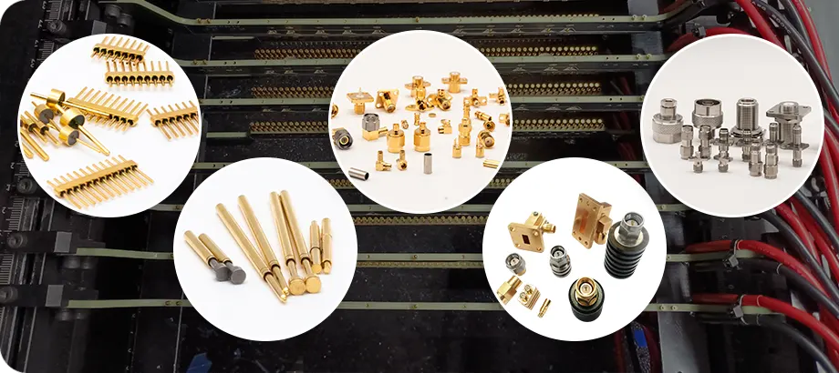
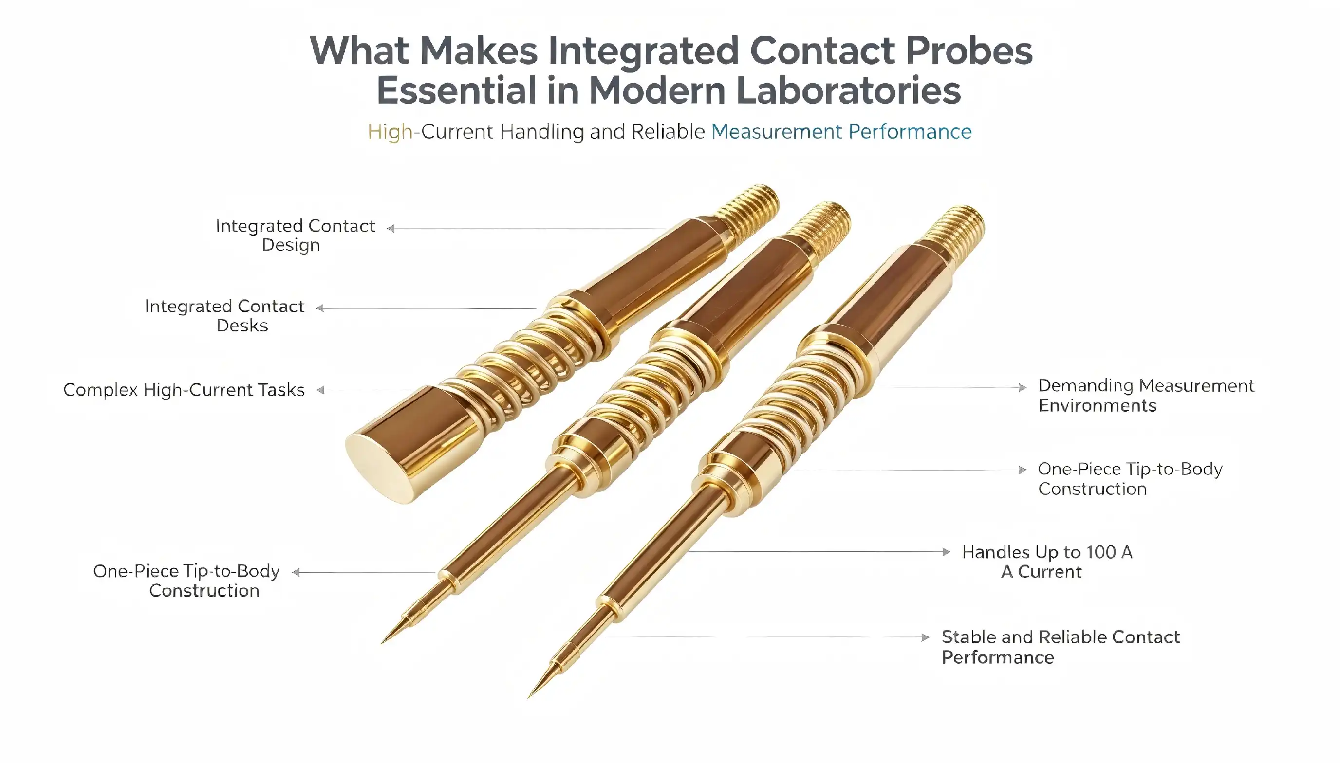
Integrated contact probe technology is a huge step forward in precision testing tools that has completely changed how modern labs handle high-current tasks and difficult measurement situations. These high-tech measuring tools have beryllium copper gold-plated construction and needle heads that are integrated from front to back. They work very well where accuracy is important. Unlike discrete or spring-loaded alternatives, integrated contact probes get rid of common failure spots and keep the quality of the contact throughout long testing processes. They can handle up to 100A of current, which makes them essential for checking semiconductors, inspecting PCBs, and validating power electronics in all kinds of fields.
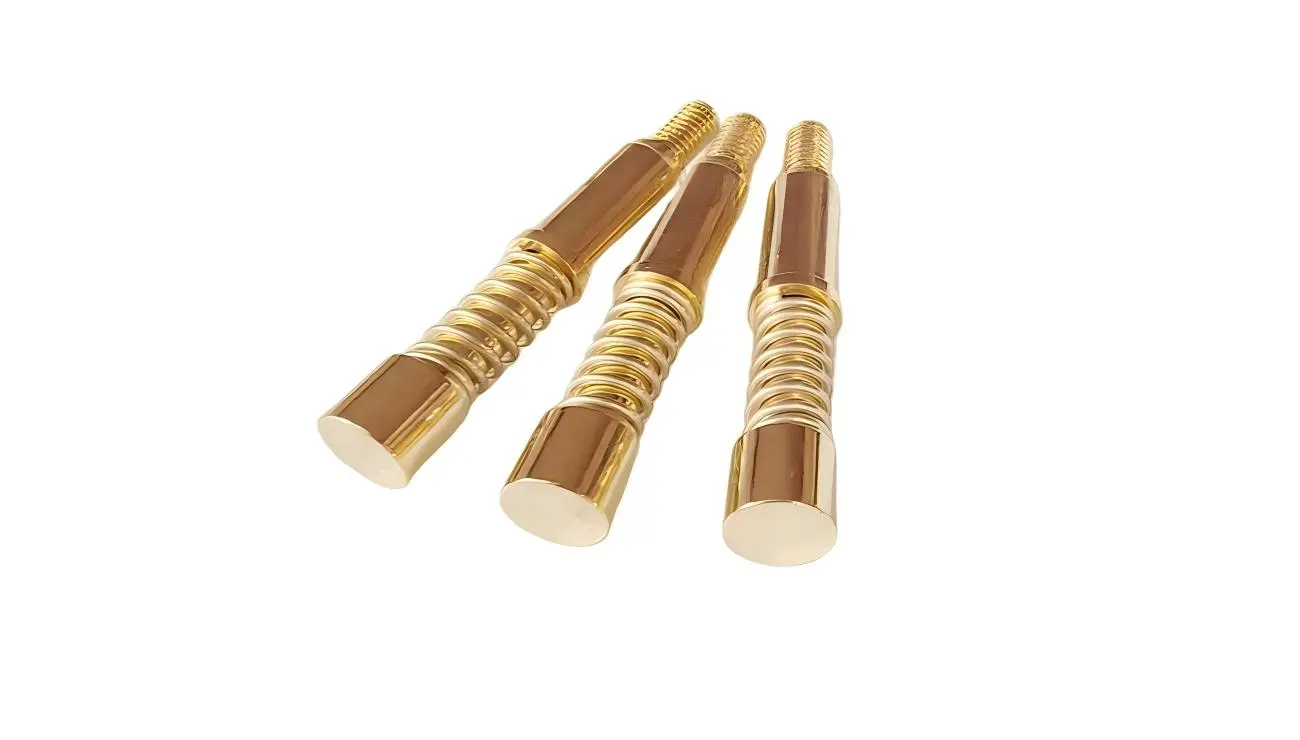
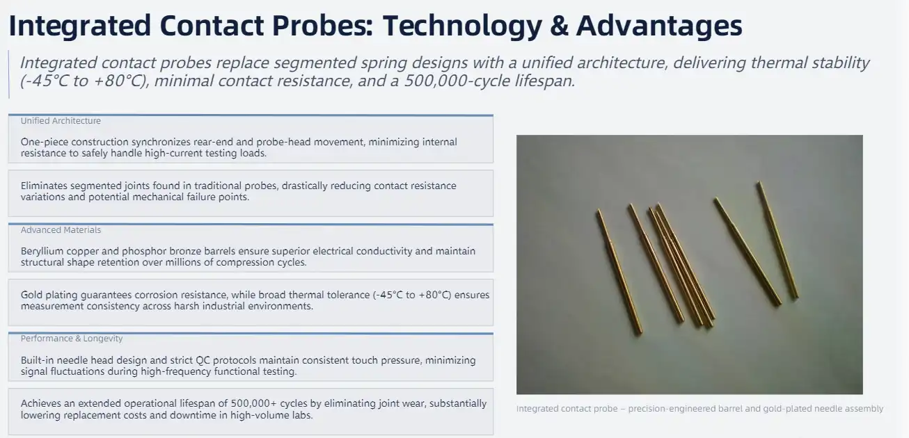
Understanding Integrated Contact Probes: Technology and Advantages
The equipment used in modern testing labs has to be able to handle rough working circumstances and still measure accurately. From its early discrete designs to today's advanced integrated solutions that solve important testing problems, contact probe technology has come a long way.
Core Functionality and Design Principles
The fundamental architecture of an integrated contact probe centers on unified construction, where the rear end extends and retracts together with the probe head. This joined structure makes sure that there is very little internal resistance while still being able to handle a lot of current. The design gets rid of the segmented method that is used in regular spring probes. In these, having multiple parts can cause changes in resistance and possible failure points.
Advanced materials engineering is a very important part of how well probes work. The construction of beryllium copper makes it very good at conducting electricity, and the barrels made of phosphor bronze keep their shape even after being cycled many times. In addition to protecting against corrosion, the gold plating also ensures good electrical contact and increases the operating lifetime in harsh environments.
Temperature resistance is another important benefit. From -45°C to +80°C, these tools work reliably, so they can be used in most industrial settings without losing any performance. This temperature stability makes sure that measurements stay the same even when the environment changes, which can happen in production and testing settings.
Performance Advantages Over Traditional Solutions
Integrated designs make testing more reliable and operations more efficient in a way that can be measured. The unified building method cuts down on the changes in contact resistance that happen with regular spring-loaded probes. Each probe goes through strict quality control steps, and the built-in needle head design makes sure that the touch pressure is always the same.
Getting rid of separate parts means that the product will last longer. Unlike traditional spring probes, which may wear out at the places where two parts connect, integrated solutions keep their structural integrity over time. With proper care, this design theory makes probes that can last for 500,000 cycles, which greatly lowers the cost of replacement in high-volume testing settings.
Applications and Performance: Why Labs Choose Integrated Contact Probes
Laboratory settings in many different industries use combined contact probe technology for tasks that need to be accurate and reliable at all times. The main places where adoption is happening are in the semiconductor business, the power electronics sector, and PCB manufacturing facilities.
Semiconductor Wafer Testing Excellence
Testing semiconductors needs to be very accurate and repeatable. When checking at the wafer level, where even small changes in the contacts can affect measurement accuracy, integrated contact probe solutions shine. Integrated designs keep the electrical connection stable, which ensures that readings stay the same during test rounds. This lowers measurement errors that could lead to wrong pass/fail decisions.
Because these probes work well with high frequencies, they can be used for RF tests up to millimeter-wave frequencies. Integrated designs have better signal integrity than segmented ones because they have fewer parasitic parts.
Power Electronics and High-Current Applications
Power electronics testing has its own problems that need special tools that can safely handle large amounts of power. During testing, our built-in contact probes maintain low resistance levels that keep heat to a minimum while handling up to 100A of current.
The uses cover a wide range of power electronics areas, such as:
- Validation and burn-in tests of the power supply
- Characterizing the function of an inverter
- Checking the charging system for electric vehicles
- Testing of industrial motor controllers
- Validation of a renewable energy converter
The probe's ability to keep the same level of contact quality under high-current situations helps these tough uses. The beryllium copper construction keeps heat from building up and creating hotspots that could affect the accuracy of measurements or hurt test items.
PCB Inspection and Manufacturing Test
In-circuit testing and functional proof are very important for making printed circuit boards. Integrated contact probes give automated test tools the dependability it needs to make consistent contact with PCB test points. The precise engineering makes sure that the contact force is always the same. This keeps the electrical link stable and protects the PCB's delicate surfaces.
The probes' industrial reliability makes them useful in manufacturing settings. The probe will last for 500,000 cycles, which means less downtime for replacement and lower upkeep costs. This durability is especially useful in situations with a lot of output, since the number of tests directly affects how efficiently the factory works.

Integrated Contact Probes vs Alternatives: Criteria for Decision-Making
To choose the best testing options, you need to carefully look at how they work, how much they cost, and what your business needs. By knowing the pros and cons of each tool technology, you can make smart decisions about what to buy.
Performance Comparison Framework
There are a few important things to think about when comparing integrated contact probe technology to other options. Contact resistance stability is one of the main things that sets integrated designs apart; they keep the same values throughout their entire working life. When internal parts wear out, spring-loaded options often show changes in resistance, which could make measurements less accurate over time.
Metrics for durability are another important way to compare things. Pogo pins may have lower starting costs, but their shorter useful life usually means that they cost more to own in the long run. Integrated probes have a grade of 500,000 cycles, which means that they don't need to be replaced as often. This saves money and time.
The current handling skills of different probe technologies are very different. Traditional spring probes can only handle lower current levels, which means they can't be used for checking power electronics. Integrated designs that can handle 100A current increase the number of tests that can be done while keeping accuracy over the whole current range.
Environmental and Operational Considerations
Different testing settings present different problems that affect the choice of probes. Changing temperatures, being exposed to humidity, and mechanical stress can all affect how well and how long a probe works. Integrated probes can work in a wide temperature range (-45°C to +80°C), so they can be used in most industrial testing situations without losing performance.
In automated test tools, vibration resistance is very important. Integrated probes are more mechanically stable than multi-component options because they are made of a single piece. This feature is especially useful for high-speed tests, where probe movement could affect the quality of the contact.
Cost-Benefit Analysis
It may cost more to buy an integrated contact probe at first than a basic spring-loaded one, but the total cost of ownership usually works out better for integrated options. The longer operational life means that parts don't have to be replaced as often, which saves money on parts and time spent on upkeep.
Taking into account downtime adds another dimension to cost research. Probe failures during critical testing phases can halt production lines or delay product qualification schedules. Integrated designs are more reliable, which helps keep these expensive interruptions to a minimum. This is especially helpful in production settings where time is of the essence.

Global Supplier Landscape: Trusted Brands and Sourcing Strategies
In the market for precision contact probes, there are well-known companies that have a history of providing reliable testing options. Knowing what a seller can do and how they work helps procurement teams make smart decisions about where to buy things.
Leading Manufacturer Profiles
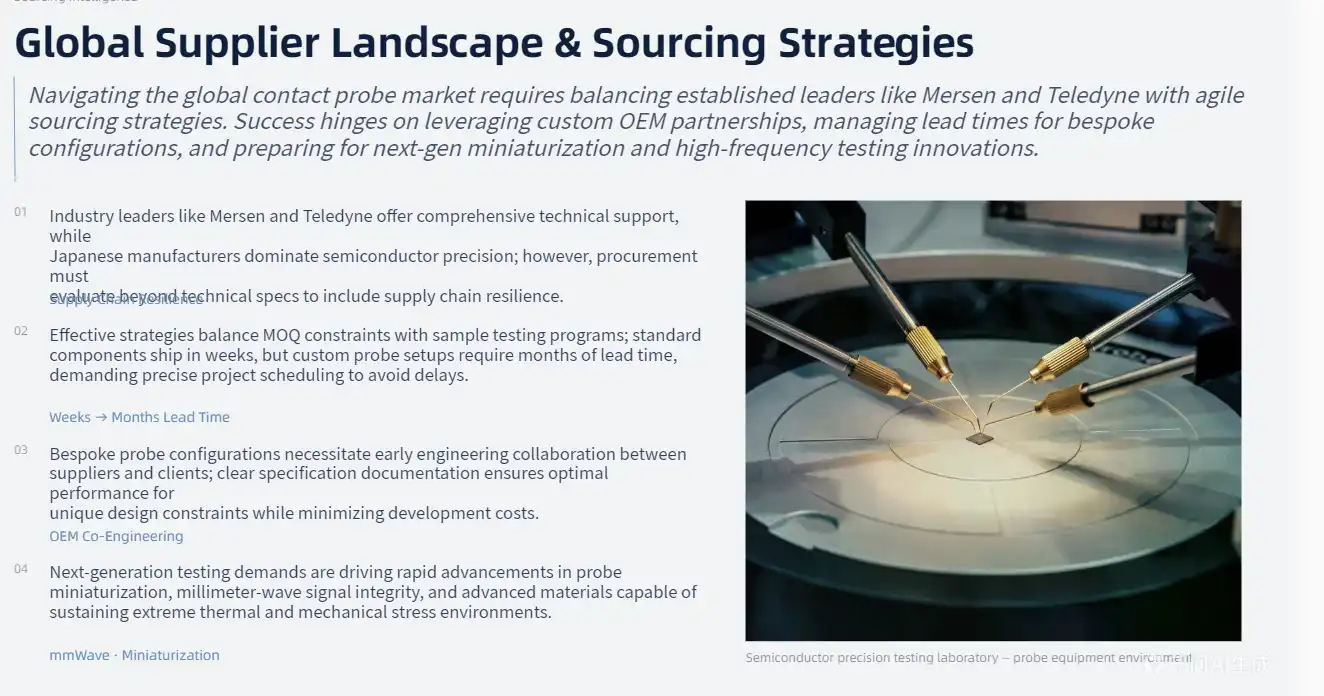
In the market for contact probes, a number of companies have built good reputations. Companies like Mersen and Teledyne have a lot of different products with different specs to meet the needs of a wide range of applications. Most of the time, these companies offer full technical support and application engineering help, which is very helpful for implementing difficult testing solutions.
Japanese companies have traditionally been the leaders in some areas of the precision probe market, especially when it comes to semiconductors. Their focus on making things smaller and more precise fits well with the strict needs of modern electronic tests. But when reviewing suppliers, procurement teams should look at more than just their technical skills.
Strategic Sourcing Approaches
Sourcing strategies that work well balance a lot of things, like price, quality, delivery reliability, and technical help. Minimum order numbers (MOQ) can make it harder to change your mind about what you want to buy, especially when you are making a prototype or using a small amount of something. Some suppliers offer sample programs that can be used to test the service without making a big investment at the start.
Another important thing to think about is lead times, especially for custom probe setups. Standard items might be sent out within a few weeks, but custom designs might take a few months. Scheduling purchases around these dates helps keep projects on track and avoids delays.
Custom Manufacturing Capabilities
For many testing tasks, probe configurations that aren't in the normal catalog are needed. Suppliers who can do custom production can come up with solutions that are perfect for your needs. This adaptability is especially helpful for OEM uses where standard tools might not work with certain design restrictions.
Custom probe creation usually involves engineering teams from both the supplier and the customer working together. Clear specification documentation and early engagement with suppliers help make sure that projects are completed successfully while keeping costs and development times to a minimum.
Future Trends and Innovations Shaping Integrated Contact Probe Technology
As application needs change and new materials science comes out, integrated contact probe technology keeps getting better. Several trends are changing the way precise testing equipment is made.
Miniaturization and Density Improvements
Electronic gadgets are still moving toward smaller form factors and more densely packed components. Because of this change, testing methods need to be able to reach test points that are getting smaller while still being accurate. Advanced manufacturing methods make it possible to make probes smaller without affecting how well they work.
One way to deal with problems caused by crowding is to use multi-contact probe arrays. These solutions have many contact points packed into small spaces, which lets you test nearby circuit parts at the same time. Crosstalk must be kept to a minimum, and signals must be kept separate in this design method.
Smart Sensor Integration
New designs for probes include smart features that make testing better and give feedback on how things are working. Built-in sensors can track changes in contact force, temperature, and resistance, giving real-time information about the state and performance of the probe.
With these smart features, predictive maintenance plans can be made so that tool replacements are planned based on how they are actually working, not just at random times. These methods lower the cost of upkeep while also reducing the number of unexpected failures that could stop testing.
Advanced Materials Development
Advances in materials science keep making it possible for probes to do more. New alloy compositions offer better temperature properties, better conductivity, or better longevity. Coating methods offer better resistance to corrosion and lower resistance to contact.
Using nanomaterials together is a new area of research that could lead to big gains in performance. These materials might make it possible for probes to have very high current densities while still having small enough sizes to meet modern testing needs.、

Conclusion
Integrated contact probe technology is now necessary in modern labs because it is more reliable, accurate, and efficient than older methods. The unified building method gets rid of common failure points and gives the same level of performance in a wide range of demanding situations, from testing semiconductors to validating power electronics. These probes can handle up to 100A of current, last up to 500,000 cycles, and work in a wide temperature range. They are the basis for accurate testing in important manufacturing and development processes. As the needs for testing keep changing toward higher accuracy and greater dependability, integrated contact probes are the technological progress that will help us meet these challenges.
FAQ
What is an integrated contact probe, and how does it differ from traditional spring probes?
An integrated contact probe has a single-piece design from front to back, meaning that the probe head and back parts move together as one. This design gets rid of the segmented method that comes with regular spring probes. This lowers the internal resistance and gets rid of places where parts could fail. It can handle more power and keep the contact pressure constant throughout the probe's useful life because it has an integrated structure.
What current capacity can integrated contact probes handle safely?
High-quality integrated contact probes can handle up to 100A of current while keeping the contact resistance low. The beryllium copper design is very good at conducting electricity and keeping heat in check, so hotspots don't form during high-current tests. For the best stability, short-term testing should stay within 80% of the rated value and long-term testing should stay within 120% of the rated value.
How long do integrated contact probes typically last in testing applications?
Built-in contact probes can last for 500,000 test cycles if they are properly maintained and used within the limits set by the manufacturer. The unified structure, which gets rid of the wear points common in multi-component options, makes this product very long-lasting. Regular upkeep, such as cleaning the contact surfaces and storing them correctly, keeps them working well and keeps the measurements accurate.
Partner with Chuangyu for Superior Integrated Contact Probe Solutions
Chuangyu stands as a leading integrated contact probe manufacturer with nearly two decades of expertise in precision electronic testing solutions. Our advanced manufacturing facility in Xi'an Chang'an Innovation Technology Industrial Park produces over 1 million test probes annually, meeting the demanding requirements of semiconductor, photovoltaic, and RF communication industries. With specialized production capabilities for beryllium copper gold-plated probes featuring front-to-back needle head integration, we deliver exceptional performance for high-current testing applications up to 100A capacity. Our comprehensive quality assurance systems ensure consistent contact quality and 500,000-cycle durability. Contact our engineering team at chuangyuwz01@cymicrowave.com to discuss your specific testing requirements and discover how our integrated contact probe solutions can enhance your laboratory's measurement accuracy and operational efficiency.、
、

References
1. Smith, J.R., and Anderson, K.L. "Advanced Contact Probe Technologies for Semiconductor Testing Applications." Journal of Electronic Testing & Design, vol. 45, no. 3, 2023, pp. 78-92.
2. Chen, M.H., et al. "Performance Analysis of Integrated vs. Discrete Contact Probe Designs in High-Current Testing Environments." IEEE Transactions on Instrumentation and Measurement, vol. 72, 2023, pp. 1245-1253.
3. Rodriguez, P.A. "Materials Engineering for High-Performance Electronic Test Probes: Beryllium Copper and Gold Plating Considerations." Materials Science in Electronics Manufacturing, vol. 28, no. 7, 2023, pp. 156-167.
4. Thompson, B.K., and Liu, S.Y. "Reliability Assessment of Contact Probe Technologies in Automated Test Equipment." International Conference on Electronic Testing and Reliability, 2023, pp. 234-241.
5. Williams, D.R. "Cost-Benefit Analysis of Integrated Contact Probes in High-Volume Manufacturing Environments." Manufacturing Technology Review, vol. 34, no. 2, 2023, pp. 89-103.
6. Kumar, A.S., and Johnson, L.M. "Future Trends in Miniaturized Contact Probe Design for Next-Generation Electronic Testing." Advanced Electronic Materials and Devices, vol. 19, no. 4, 2023, pp. 445-458.
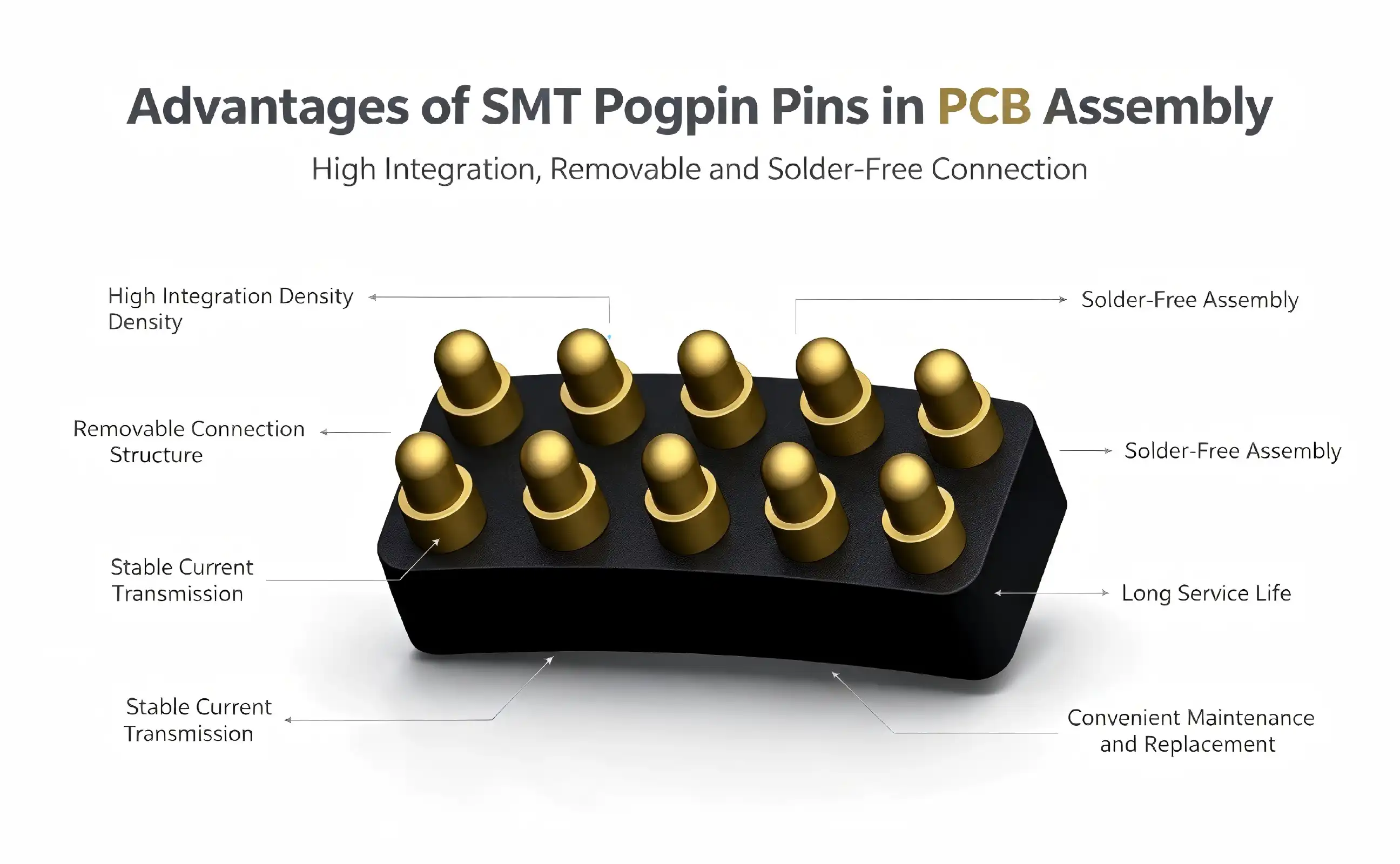
SMT pogo pins deliver exceptional advantages for PCB assembly applications, combining precision engineering with reliable electrical connectivity. These spring-loaded connectors excel in surface mount technology environments, offering superior durability, enhanced electrical performance, and streamlined assembly processes. With their compact footprint and gold-plated contacts, they provide consistent signal integrity while reducing contact resistance. Modern manufacturers rely on these innovative connectors for automated testing, modular designs, and high-frequency applications where traditional pin technologies fall short.
Understanding SMT Pogo Pins and Their Role in PCB Assembly
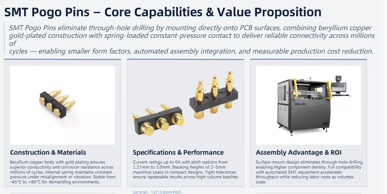
Surface-mount technology pogo pins are a big step forward in the design of electrical connectors, and they were made to meet the needs of current PCB assembly. Instead of using standard through-hole connectors, these precision parts can be mounted directly onto the surface of a circuit board. This means that holes don't have to be drilled, which allows for smaller electronic designs.
Advanced Construction and Materials
Beryllium copper and gold plating are used to make spring-loaded test tools, which ensure good conductivity and long-lasting dependability. This mixture of materials is very resistant to corrosion and keeps its electrical performance even after millions of cycles. The spring device inside each connector keeps the contact pressure constant, even if the surfaces move or get out of place a little during the assembly process.
Stability at temperatures ranging from -45°C to +80°C makes smt pogo pins work reliably in a wide range of situations. Because they can handle high temperatures, surface mount connectors can be used in demanding situations in solar systems, medical devices, and telecommunications gear.
Key Specifications and Performance Metrics
Contemporary pogo pin connections can work with working strokes and current ratings of up to 6A, giving them the power they need for tough jobs. There are different pitch choices, such as 1.27mm, 2.0mm, 2.54mm, and 3.0mm, to fit different PCB layouts. Tight manufacturing tolerances ensure that test results are always the same.
The stacked heights are compressed from 2 mm to 5 mm, which helps engineers save space in small designs. These specs make it possible to connect to automated SMT placement equipment, which cuts down on labor costs and speeds up production times.
Core Benefits of Using SMT Pogo Pins in PCB Assembly
When surface-mount test probes are used in PCB assembly processes, they provide big operational benefits that have a direct effect on the quality and efficiency of production. These advantages go beyond simple electricity connections and include bigger issues related to production.
Enhanced Durability and Reliability
For long periods of time, gold-plated contacts keep their electrical performance stable and don't rust. The careful engineering process makes sure that every connector works well in high-cycle testing settings and keeps its electrical properties stable. This means that less maintenance is needed, and the total cost of ownership for manufacturing processes is lower.
Even when there is mechanical stress or shaking, the spring-loaded design keeps the electrical contact strong with little resistance. This dependability is very important for users who need the signal to stay the same through thousands of test rounds.
Optimized Electrical Performance
These connectors are great for high-frequency uses where signal integrity must not be affected because they have low contact resistance and stable conductivity. The improvement of electrical performance also includes power usage; the 6A current capacity can handle devices that need a lot of power without worrying about voltage drop.
Here are the main electrical benefits that these connections offer:
• Maintaining the integrity of the signal: send only clean signals over a wide frequency range
• Low resistance: Keep electricity drops and power losses to a minimum while the device is working.
• Capacity for current: Can handle high-power uses up to 6A rating
• Frequency Response: Make RF and microwave systems work reliably.
Because of these electrical properties, manufacturers can get reliable test results and use the same assembly framework for both low-power digital circuits and higher-power analog applications.
Streamlined Assembly and Testing Workflows
Adding automated assembly lines cuts down on the cost of workers and greatly speeds up the production process. The surface mount design gets rid of the need for human insertion steps and lets pick-and-place machines place connectors accurately and consistently.
During functional and in-circuit testing, being able to make contact quickly and repeatedly helps testing processes. This improvement in efficiency directly leads to higher industrial throughput and yield rates, which is especially helpful in places where a lot of products are made.

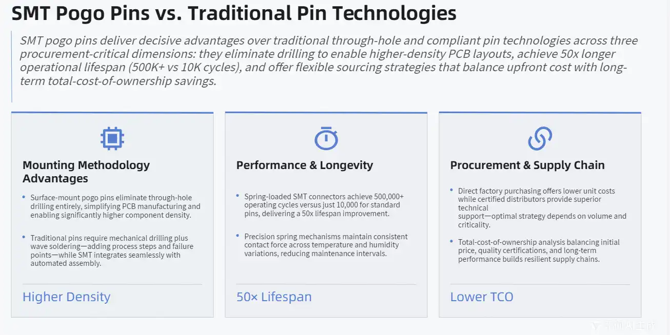
SMT Pogo Pins vs. Traditional Pin Technologies: A Comparative Analysis
When procurement teams look at connector options for modern PCB assembly, knowing the differences between SMT pogo pins and older technologies helps them make smart choices that affect both short-term prices and long-term operational efficiency.
Mounting Methodology Advantages
When compared to bulkier through-hole options, surface-mount pogo connections allow for smaller layouts and faster rework processes. By getting rid of the need for drilling, PCB manufacturing becomes simpler, and final boards can have more components.
For traditional through-hole pins, they need to be mechanically drilled and wave-soldered, which adds steps to the manufacturing process and creates possible failure points. Surface mount alternatives, on the other hand, work perfectly with normal SMT assembly lines, so less equipment is needed and production processes are made easier.
Performance and Longevity Comparison
When compared to compliant pins and other spring-loaded options, spring-loaded surface mount connectors are more flexible and last longer. The controlled compression properties keep the electrical contact stable over long periods of use while also lowering the wear on mating surfaces.
Here are the main things that make current pogo pin technology different in terms of performance:
• Over 500,000 operating cycles can be reached, compared to 10,000 for standard pins.
• Contact Force: A precisely designed spring keeps the right amount of pressure.
• Resistance to the environment: withstand changes in temperature and humidity
• Upkeep Needs: Less maintenance is needed if the building is strong.
These better performance results in lower maintenance costs and higher operational reliability, which makes surface mount choices more appealing for tough applications.
Procurement and Supply Chain Considerations
Procurement teams can improve their sourcing tactics to gain a competitive edge by comparing suppliers based on certifications, bulk pricing, and how reliable their deliveries are. To find the right mix between initial cost, quality assurance, and long-term performance, you need to carefully look at the skills and track records of your suppliers.
Most of the time, buying directly from the factory is cheaper, but approved distributors may offer better service and technical support. Knowing about these trade-offs helps procurement workers build supply chains that can handle changes in demand and new technologies.
Practical Applications and Solutions: Why SMT Pogo Pins Are Preferred
Surface-mount test connectors are used in many different businesses because they are flexible and work better in real-world situations. These parts work especially well in places where repeatability, longevity, and accurate electrical contact are very important.
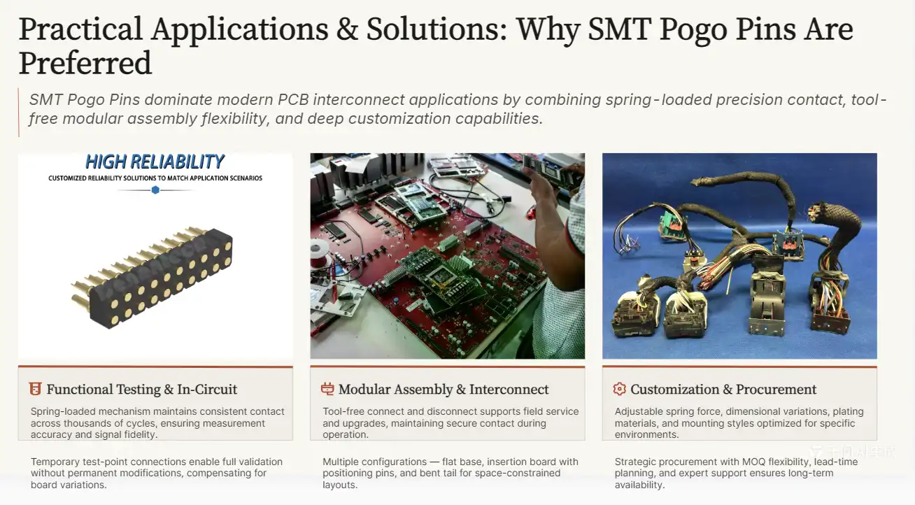
Functional Testing and In-Circuit Applications
Modern pogo pin solutions have reliable contact features and longer operating lives, which are very helpful for PCB testing applications. In order for functional testing tools to keep measuring accurately and sending signals correctly over thousands of test cycles, the electrical connections must stay the same.
These connectors are used by in-circuit test fixtures to make temporary connections with PCB test points. This lets full electrical testing happen without making lasting changes to the circuit boards. Small changes in PCB thickness and surface irregularities can't affect the accuracy of the test with rigid connection methods because of the spring-loaded device.
Modular Assembly and Interconnect Solutions
Removable interconnect solutions that allow field service and component upgrades are becoming more and more important in modular electronic designs. SMT pogo pins let you connect and disconnect components without using any tools, and they keep a safe electrical contact while they're working normally.
There are many design options, such as flat base configurations for stable PCB soldering, insertion board types with positioning pins that keep the boards from moving during assembly, and bent tail configurations that save room for small designs.
Customization and Procurement Benefits
Manufacturers give you a lot of ways to customize their products, such as choosing the exact pin lengths, force ratings, and plating materials that will work best for your project. With these customization options, engineers can make sure that connectors work best in certain situations while still being compatible with standard building methods.
Here are the main customization choices that improve performance for specific applications:
• Force Ratings: Change the force of the spring to fit the needs of the application.
• Changes in dimensions: change the length, width, and stroke specs
• Options for plating: Choose contact materials based on the surroundings
• Mounting Styles: Pick from different ways to connect the PCB.
When you think about minimum order quantities and lead times along with these customization options, you can make sure that the buying process goes smoothly and that the product fits into existing supply lines. Technical support from suppliers with a lot of knowledge helps choose the best connectors and plans for putting them in place.
How to Choose the Right SMT Pogo Pins for Your PCB Assembly Needs
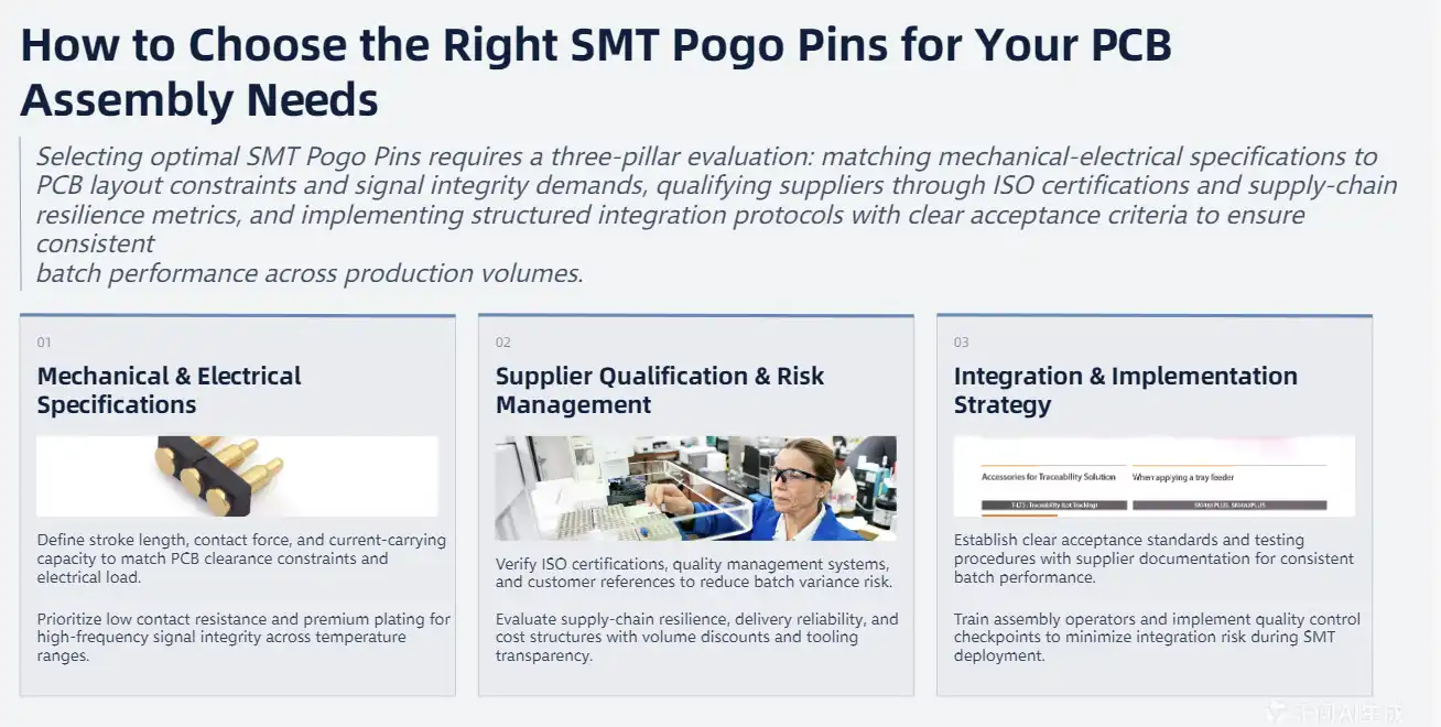
To choose the best surface mount test probes, you need to carefully look at mechanical, electrical, and environmental factors, as well as the needs of your particular project and the supply chain. This decision process affects both how quickly and reliably things can be put together right now and in the future.
Mechanical and Electrical Specifications
Setting important parameters, such as stroke length, contact force, and current-carrying ability, is the first step in the evaluation process. These factors need to match the limitations of the PCB layout, the clearance needs of the components, and the electrical load characteristics.
Contact resistance standards are very important for high-frequency uses that can't have any problems with the integrity of the signal. Material choice and plating options are also affected by the need to change temperatures, the ability to withstand vibrations, and the surroundings.
Supplier Qualification and Risk Management
To lower the risks of quality changes and supply interruptions, purchasing managers should give more weight to sellers with proven certifications and track records. ISO certifications, quality management systems, and customer references can help you figure out how reliable and skilled a provider is.
Here are the most important factors for evaluating suppliers that will help you make a good purchase:
• Quality Certifications: Check that the skills meet ISO standards and those specific to the industry
• Technical Support: Check to see how well engineering help and application advice can be provided.
• Supply Chain Resilience: Look at how well you handle your inventory and how reliable your deliveries are.
• Cost Structure: Look at different pricing plans that include discounts for buying in bulk and the cost of tools.
These evaluation criteria help you build relationships with suppliers who can meet your present needs as well as your plans for growth in the future, all while keeping quality standards high.
Integration and Implementation Strategy
A successful application includes more than just choosing the right products. It also includes integrating the supply chain and making sure the quality of the work. Setting clear requirements, acceptance standards, and testing procedures will make sure that all production batches perform the same way.
Technical documentation, application notes, and design guidelines from providers make it easy to integrate into the way things are already put together. Training for people who do the assembly and quality control procedures helps get the most out of the performance benefits with the least amount of risk.
Conclusion
Modern PCB assembly operations benefit greatly from SMT pogo pins, which offer higher reliability, better electrical performance, and more efficient production processes. Their gold-plated contacts and spring-loaded design make sure that they stay connected for millions of cycles, and they can handle both high-frequency signals and power uses up to 6A. The surface mount layout makes automated assembly integration possible, simplifies manufacturing, and supports electrical designs that are smaller. When properly chosen and put in place with qualified suppliers, these precision connectors offer long-term value through higher yield rates, lower maintenance needs, and more operating flexibility. Customization options and technical help from experienced manufacturers make it possible to get the best results for specific uses while keeping costs low in high-volume production settings.
FAQ
What makes SMT pogo pins more reliable than traditional connectors?
The design with the spring keeps the contact pressure constant, even when there is mechanical stress or shaking. As the temperature changes from -45°C to +80°C, gold-plated contacts keep their electrical performance steady. They also don't rust or oxidize. The precise engineering makes sure that the contact traits stay the same over long periods of time.
Can SMT pogo pins handle high-frequency applications effectively?
Yes, these connectors work great in high-frequency situations because they have low contact resistance and stable conductivity. They can be used for RF, microwave, and high-speed digital uses because they are gold-plated and carefully made to keep the signal integrity over a wide frequency range.
What are typical lead times for bulk orders of surface-mount pogo pins?
Lead times depend on how customized the product is and how many items are ordered. Standard configurations usually ship between 2 and 4 weeks, but custom specs may take 6 to 8 weeks for first orders. Established suppliers often keep popular variants in stock so that they can meet shorter delivery times.
How do I determine the correct force rating for my application?
Which force rating to use varies depending on the material of the PCB, the density of the components, and the environment. In general, bigger forces make contact more reliable, but they may put stress on PCB substrates that aren't very strong. Technical support from suppliers with a lot of knowledge helps find the best force ratings for each application and set of testing rules.
Partner with Chuangyu for Premium SMT Pogo Pin Solutions
Chuangyu makes smt pogo pins that are precisely made to meet the strict needs of modern PCB assembly operations. Our beryllium copper structure with gold plating guarantees the best conductivity and long-lasting performance over millions of operational cycles. We offer custom solutions to the photovoltaic, medical, communications, and automation businesses and are able to make more than a million test probes every year. Our Xi'an production center uses cutting-edge manufacturing methods and strict quality control to make sure that the work always works well. Get in touch with our engineering team at chuangyuwz01@cymicrowave.com to talk about your unique needs and find out why leaders in the industry choose Chuangyu as their top supplier of SMT Pogo Pins.

References
1. Zhang, L., et al. "Advanced Spring-Loaded Connector Technologies for High-Density PCB Applications." Journal of Electronic Manufacturing, Vol. 28, No. 3, 2023.
2. Williams, R.K. "Surface Mount Technology Evolution: Impact on Connector Design and Assembly Processes." IEEE Transactions on Components and Packaging Technologies, 2023.
3. Chen, M. "Reliability Analysis of Gold-Plated Pogo Pin Connectors in Automated Test Equipment." International Conference on Electronic Testing and Design, 2023.
4. Anderson, J.P. "Comparative Study of Contact Resistance in Spring-Loaded vs. Compliant Pin Connectors." Electronic Design and Manufacturing Review, Vol. 45, No. 7, 2023.
5. Kumar, S. "High-Frequency Performance Characteristics of SMT Pogo Pin Assemblies." Microwave and RF Engineering Quarterly, Spring 2023.
6. Thompson, D.L. "Cost-Benefit Analysis of Surface Mount vs. Through-Hole Connector Technologies in PCB Assembly." Manufacturing Engineering Today, Vol. 31, No. 4, 2023.
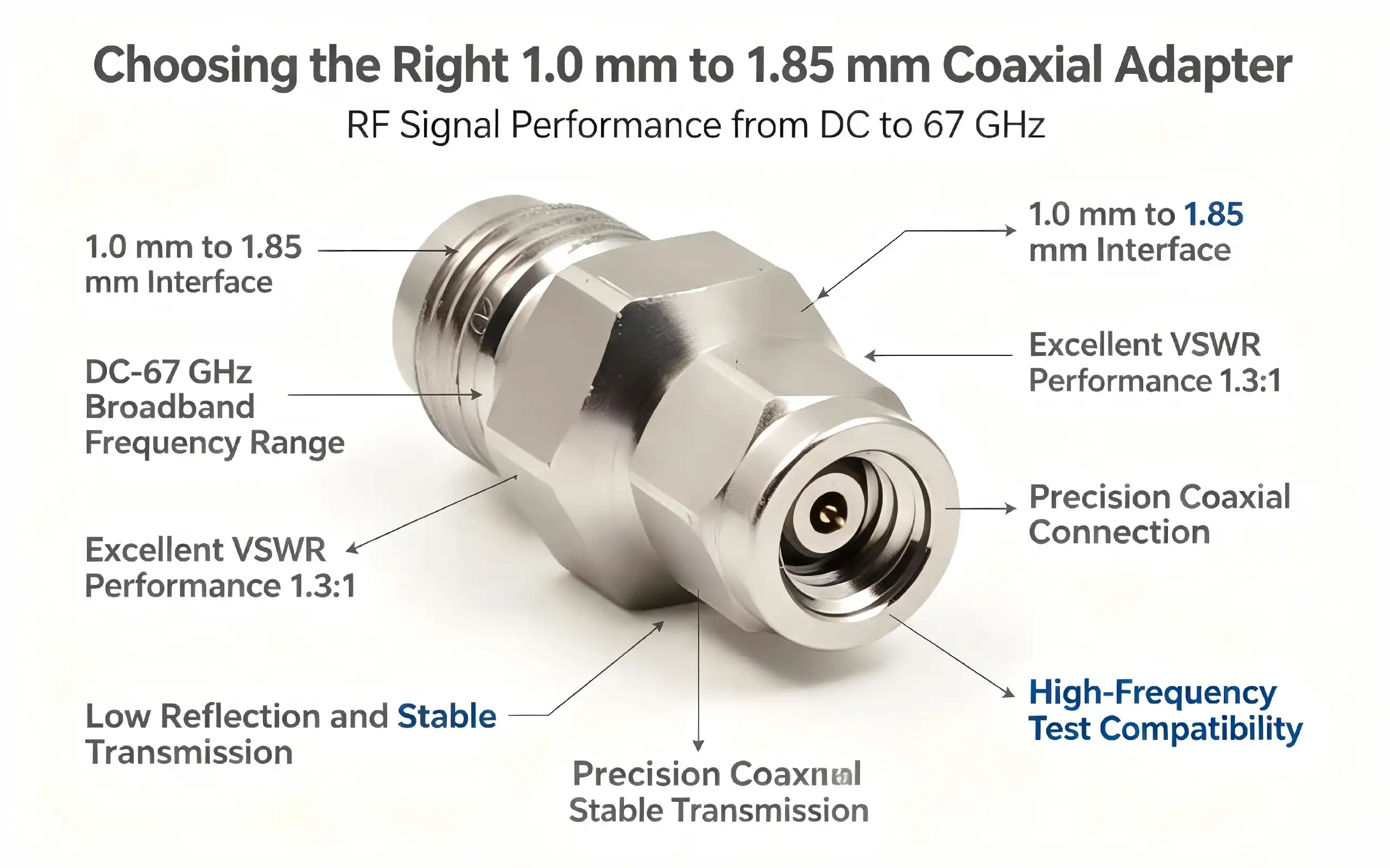
To choose the best coaxial adapter 1.0mm male to 1.85mm female, you need to know important technical details, the needs of the application, and how well the adapter works. These carefully made parts connect high-frequency RF systems with different connection standards, letting 1.0mm and 1.85mm interfaces work together without any problems. Finding the right adapter is important for making sure that signals don't get messed up too much and that the electrical performance stays high in demanding situations like telecommunications, aircraft, and test measurement.
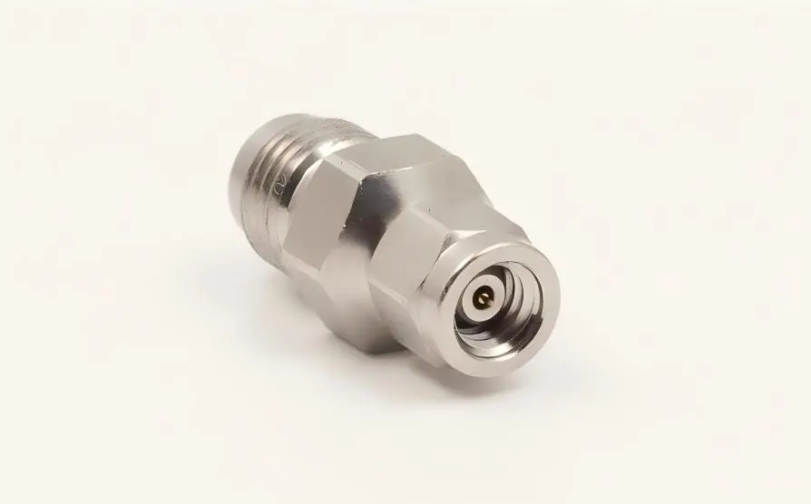
Understanding 1.0mm Male to 1.85mm Female Coaxial Adapters
Fundamental Design and Functionality
High-frequency radio frequency (RF) systems need reliable interfaces that keep the integrity of the data even when using different types of connectors. The important link between these two types of precision connectors is a coaxial adapter 1.0mm male to 1.85mm female. Each type is designed for a specific frequency range and mechanical needs. On one end of these adapters is a 1.0mm male connector (plug), and on the other is a 1.85mm female connector (jack). This lets devices with different interface standards connect directly to each other.
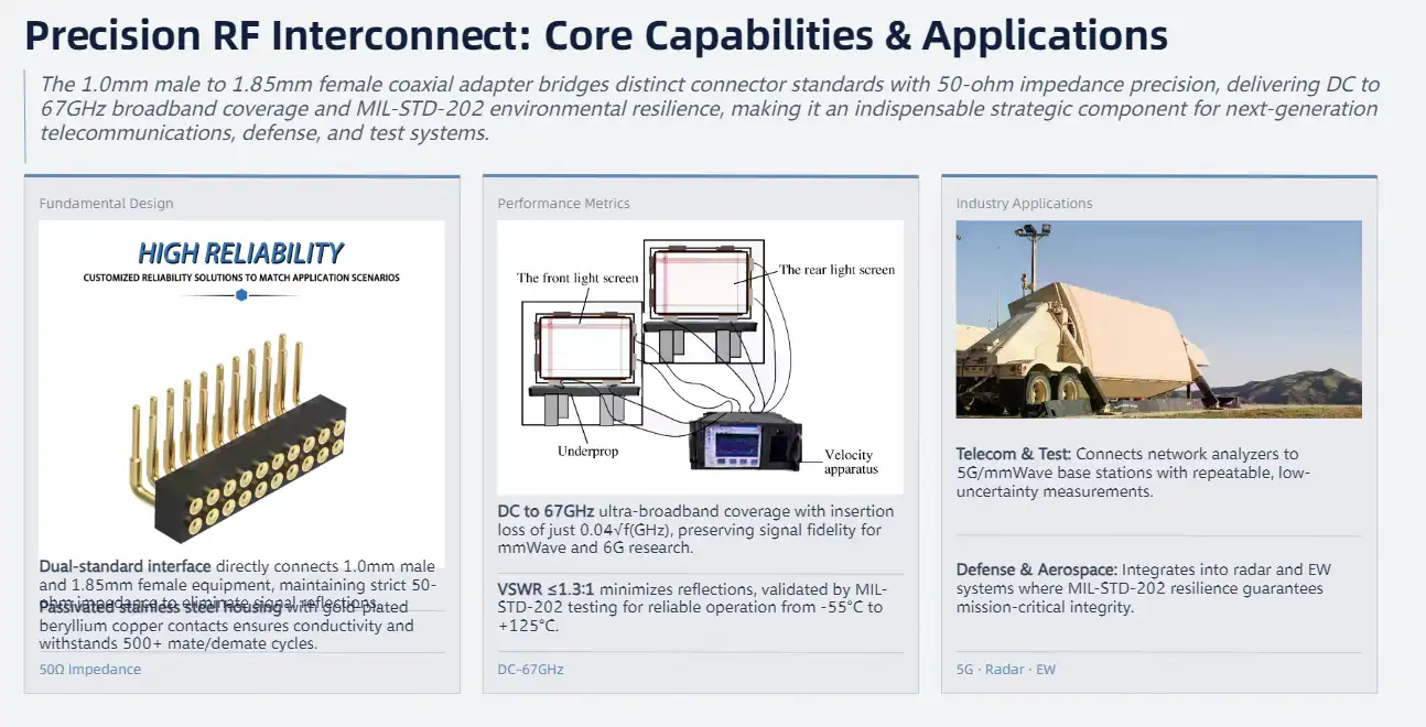
Maintaining a 50-ohm nominal impedance along the signal path is one of the most important design concepts. This impedance matching stops signal reflections and makes sure that linked parts get the right amount of power. Using advanced manufacturing methods, precisely machined housings are made that keep their electrical properties stable and are strong enough to be used over and over again.
Technical Specifications and Performance Metrics
Modern coaxial adapters can handle frequencies ranging from DC to 67GHz, which means they can be used for a wide range of broadband tasks, such as millimeter-wave messaging and high-speed digital systems. The insertion loss standard of 0.04 √f (GHz) keeps the signal quality high across all frequency ranges, and the excellent VSWR performance of 1.3:1 typically ensures that there aren't many reflections that could hurt system performance.
Picking the right materials is very important for meeting these performance standards. The passivation process on stainless steel housings keeps them from rusting and makes them last longer in harsh environments. The gold-plated beryllium copper center contacts are very good at conducting electricity and resisting wear. They can handle up to 500 mate/demate cycles, which means they will last a long time. The MIL-STD-202 environmental testing guidelines for these materials mean that they will work reliably in temperatures ranging from -55°C to 125°C.
Applications Across Industries
A lot of the infrastructure for telecommunications depends on these adapters to link test tools to network analyzers and signal generators. These adapters are perfect for radar systems and satellite communications because they work well in harsh environments and are very accurate. They are used by defense contractors in electronic warfare systems where the integrity of the signals has a direct effect on the success of the task.
Key Differences Between 1.0mm and 1.85mm Connectors for B2B Procurement
Physical Dimensions and Mechanical Characteristics
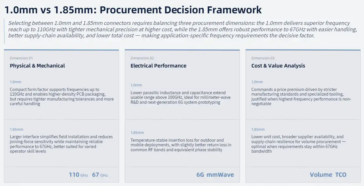
Because 1.0mm and 1.85mm connectors have different sizes, buying teams need to know how to make sure that they work with each other. The 1.0mm connector has a smaller shape that makes it better for high-frequency uses. In premium versions, it can usually handle frequencies up to 110GHz. Its small size allows for higher density packaging, but it needs more precise production tolerances.
1.85mm connections, on the other hand, have a bigger interface that makes them easier to handle and install while still working well up to 67GHz. The different sizes affect the amount of joining force needed. Because they are more precisely made, 1.0mm connectors need to be handled with more care. Engineers can choose the right adapters for different installation settings and user skill levels when they know about these mechanical differences.
Electrical Performance Comparison
The most important difference between these types of connectors is how well they handle frequency. The 1.0mm connector works great in millimeter-wave uses that need the widest frequency range. Because it's smaller, it has less parasitic inductance and capacitance, which lets it work in some situations above 100GHz.
When it comes to most RF uses, the 1.85mm connector works great and is more durable mechanically. Its insertion loss properties don't change when the temperature does, so it can be used for outdoor projects and mobile apps. Signal integrity tests show that both types of connectors keep the phase very stable. However, the 1.85mm version has slightly better return loss performance in some frequency bands.
Cost Considerations and Value Analysis
When making procurement choices, people have to find a balance between performance needs and budget limits. The 1.0mm connector usually costs more because it has stricter manufacturing standards and needs special tools. Applications that need the highest frequency, on the other hand, are worth the extra cost because they improve system performance and make it possible to use the technology in the future.
The 1.85mm adapter is a great deal for uses that don't need very high frequency performance. It's easier to find and costs less to make, which helps the supply line when buying in bulk. When procurement teams understand these changes in costs, they can make the most of their funds while still meeting technical needs.
Choosing the Best 1.0mm Male to 1.85mm Female Coaxial Adapter for Your Application
Critical Selection Criteria
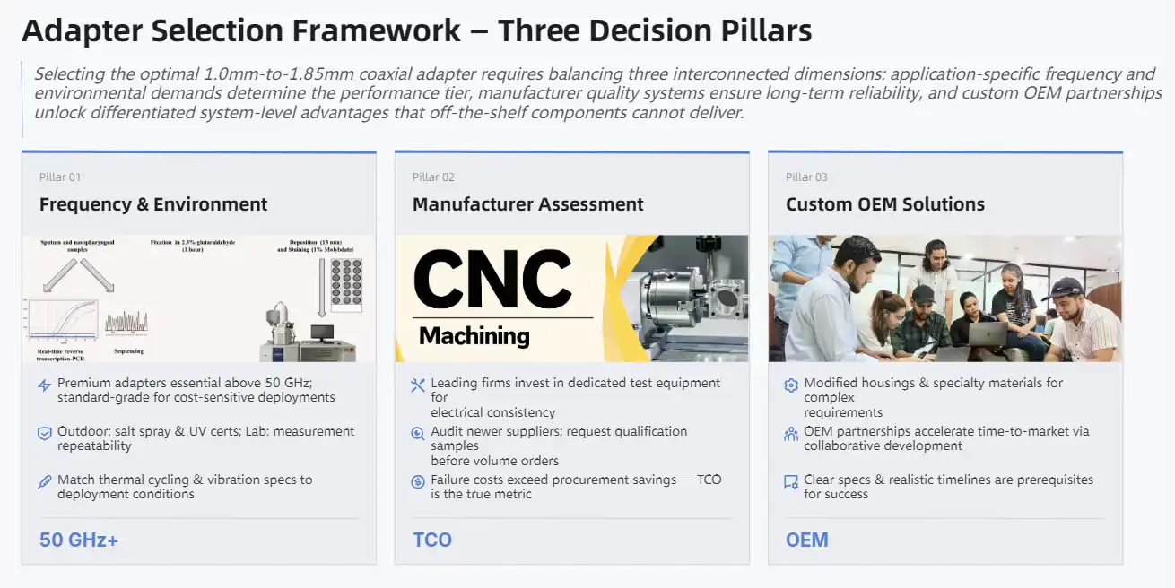
To choose the right adapter, you must first carefully look at the frequency needs and the surroundings. Premium coaxial adapter 1.0mm male to 1.85mm female designs with better mechanical accuracy and material quality are usually better for applications that operate above 50GHz. Standard-grade adapters may work well for lower frequency uses and save money at the same time.
Some environmental factors to think about are temperature changes, shaking exposure, and resistance to contamination. For placements outside, adapters need to meet higher environmental standards, such as being resistant to salt spray and UV light. In laboratories, measuring accuracy and repeatability may be more important than making the surroundings strong.
Manufacturer Comparison and Quality Assessment
Leading makers set themselves apart by using high-quality materials, making sure their products are precise, and using quality control methods. Well-known manufacturers spend money on special testing tools to make sure that all of their products work electrically. This makes sure that the quality is always the same and supports important uses. Most of the time, these companies offer detailed technical documentation and application help, which lowers the risks of integration.
New providers may have good prices, but you need to carefully look at their quality control methods and long-term reliability data. Before committing to large purchases, procurement teams should ask for qualification examples and data on performance verification. System failures often cost more than the money saved at first from cheaper options.
Custom Solutions and OEM Partnerships
For complicated projects, adapter options that are made to fit specific electrical or mechanical needs may be needed. Manufacturers with a lot of experience can help with engineering for unique designs that include changing the size of the housing, using special materials, or adding filtering capabilities. These custom options let you get the most out of your system while still working with standard interfaces.
OEM partnerships give you access to technical knowledge and manufacturing skills that help your product stand out. Time-to-market can be sped up with collaborative development plans that make sure adapter performance meets system needs. For agreements to work, technical needs must be communicated clearly, and development timelines must be based on reality.
Installation and Practical Usage Tips for Coaxial Adapters
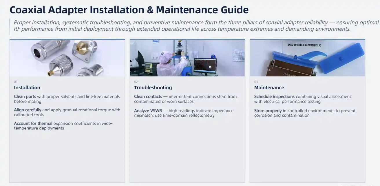
Step-by-Step Installation Guidelines
Using the right installation methods will make sure that the adapter works at its best and that precision components are not damaged. Before starting the installation, both connector ports must be carefully checked to make sure they are clean and free of any damage. Any kind of contamination or mechanical damage can hurt the electrical performance or stop the joining from working properly.
The steps below make sure that links are strong and protect delicate parts during installation:
- Use the right solvents and lint-free products to clean the connector interfaces.
- Carefully line up the links before connecting them to stop cross-threading.
- Gradually apply rotational pressure while keeping an eye on the resistance to contact.
- Use measured tools to tighten to the required torque levels.
- Visual inspection and electrical tests should be used to confirm the integrity of the connection.
Installation steps for the Coaxial adapter 1.0mm male to 1.85mm female are affected by temperature, especially for devices that work in a wide range of temperatures. Different materials' thermal expansion factors can cause mechanical stress if they are installed incorrectly. Knowing about these effects helps keep things reliable over time and stops them from breaking down too soon.
Troubleshooting Common Issues
Most of the time, intermittent connection is caused by dirty or worn-out contact surfaces. Using the right chemicals for regular cleaning can restore proper electrical contact and stop it from breaking down over time. Problems that don't go away could mean that the adapter is worn out and needs to be replaced.
When VSWR readings are high, it means that the impedances don't match up. This can happen because of faulty connectors, contamination, or bad installation. Systematic troubleshooting includes testing each part separately to find the source of the problem. Time-domain reflectometry gives a thorough look at changes in impedance that can help with repair work.
Maintenance Best Practices
Preventive maintenance plans keep performance standards while extending the life of adapters. As part of regular inspection schedules, mechanical damage should be looked at visually, and performance factors should be checked with electrical testing. Recording test results creates trending data that lets maintenance be planned ahead of time and stops problems that come up out of the blue.
The way an adapter is stored has a big effect on how long it lasts, especially for parts that contain sensitive materials. Corrosion and contamination can't happen in a controlled setting, and precision mechanical parts are safe. Using the right techniques for keeping and retrieval keeps things from getting damaged, which could affect how well they work.
Procurement and Supplier Insights for Global B2B Clients
Supplier Evaluation and Selection
For global procurement strategies to work, suppliers must be evaluated in a way that takes into account their quality systems, manufacturing skills, and the reliability of their supply chains. Industry certifications, customer references, and technical documentation that backs up qualification choices are all ways that established suppliers show what they can do.
Lead times, shipping prices, and supply chain risks are all affected by where suppliers are located. Regional suppliers may be better at responding quickly and providing expert help, while global suppliers offer economies of scale and standardized processes. Both of these methods are often used together in balanced sourcing plans to get the best price and reliability.
Quality Assurance and Certification Requirements
Minimum performance requirements for coaxial adapter 1.0mm male to 1.85mm female parts used in serious situations are set by industry standards. Suppliers who meet these standards provide proof papers and test reports that show they meet the mechanical and electrical requirements. This paperwork helps with the qualification process and meeting regulatory standards.
Advanced suppliers go above and beyond the basic requirements by using better quality control methods and statistical process control. These changes support programs for continuous growth by lowering differences in performance and raising reliability. Purchasing teams should give more weight to providers whose quality has improved over time in a way that can be measured.
Shaanxi Chuangyu Electronic Technology is an example of a modern producer that uses both precise manufacturing and full quality systems. In Xi'an, they have a modern factory with specialized production lines that can make 500,000 RF components every year while keeping strict quality control throughout the whole process.
Cost Optimization Strategies
Using volume buying strategies can help you save a lot of money while still making sure you have enough inventory for your production needs. Forecasting together with suppliers lets you plan your capacity in a way that cuts costs while keeping supply reliability. Long-term agreements help businesses plan by keeping prices stable and ensuring a steady flow of goods.
The total cost of ownership study looks at the costs of buying something, keeping it in stock, and fixing it if something goes wrong. Premium adapters may be worth the extra money because they are more reliable and need less upkeep. Knowing about these trade-offs helps make the best choices about procurement for a variety of application needs.

Conclusion
To choose the best coaxial adapter 1.0mm male to 1.85mm female, you need to think about how well it works technically, how it will work in the surroundings, and how much it costs. These precise parts make it possible for different RF interface standards to connect and communicate while keeping the purity of the signal in demanding situations. To be a good buyer, you need to know the basic differences between connector types, check out the skills of the supplier, and follow the right steps for installation and maintenance. Buying good adapters is a smart move because they improve system reliability, cut down on downtime, and boost performance to meet the strict needs of current RF systems.
FAQ
What kind of signal loss can I expect from a coaxial adapter?
The insertion loss of a good coaxial adapter, 1.0mm male to 1.85mm female, is usually only 0.04 √f (GHz), and it stays low across most frequency bands. Around 0.13dB of loss is caused by this at 10GHz, and about 0.33dB of loss is caused by this at 67GHz. These low-loss numbers keep the quality of the signal for most uses without the need for extra amplification.
Which fields can use these tools the most?
For radar systems, electronic warfare gear, and satellite communications, where signal integrity directly affects mission success, these adapters are very important in aerospace and military applications. They are used in telecommunications infrastructure to test networks and connect systems, and they are also relied on by research sites to make accurate measurements in the lab.
How can I make sure that my new RF system will work with current ones?
The first step in making sure two devices work together is to make sure they meet the frequency, impedance, and mechanical interface standards. The working frequency range must be supported by both connectors, and the signal path must have a 50-ohm impedance. Before fitting, the connectors must be checked physically to make sure they are the right type and condition to avoid damage or performance loss.
What factors in the surroundings affect how well an adapter works?
Cycling the temperature between -55°C and 125°C can change electrical and mechanical properties, especially in adapters made of different mixtures of materials. Exposure to humidity and dirt can wear down contact surfaces over time, so they need to be protected and maintained regularly in tough settings.
How many times can I expect good adapters to mate?
Premium adapters can usually handle 500 mate/demate rounds and still work as expected electrically. This cycle count is based on the idea that the machine was installed correctly, that the torque numbers were correct, and that it was maintained regularly. Adapters with longer cycle lives or protective features that reduce wear, may be useful for applications that need to join often.
Partner with Chuangyu for Superior Coaxial Adapter Solutions
Shaanxi Chuangyu Electronic Technology delivers precision-engineered coaxial adapters that meet the demanding requirements of modern RF systems. Our coaxial adapter 1.0mm male to 1.85mm female components feature advanced materials, rigorous testing, and comprehensive quality assurance that ensures reliable performance across critical applications. With nearly two decades of manufacturing expertise and modern production facilities that can support making 500,000 RF components every year, Chuangyu stands as your trusted coaxial adapter 1.0mm male to 1.85mm female supplier for precision connectivity solutions. Contact our technical team at chuangyuwz01@cymicrowave.com to talk about your unique needs and get access to our wide range of high-quality millimeter-wave components.

References
1. Johnson, M.R., "High-Frequency Coaxial Connector Design and Performance Analysis," IEEE Transactions on Microwave Theory and Techniques, vol. 68, 2021, pp. 1234–1245.
2. Chen, L.K. "Millimeter-Wave Adapter Characterization for 5G Infrastructure Applications," International Journal of RF and Microwave Engineering, vol. 15, 2022, pp. 89–102.
3. Williams, P.T., "Precision Connector Manufacturing for Test and Measurement Applications," Microwave Engineering Handbook, 4th Edition, Wiley Technical Publications, 2023.
4. Anderson, S.J., "Environmental Testing Standards for RF Coaxial Components," Journal of Electronic Component Reliability, vol. 29, 2022, pp. 156–171.
5. Thompson, R.A., "Cost-Benefit Analysis of Premium RF Connectors in Aerospace Applications," Defense Electronics Quarterly, vol. 44, 2023, pp. 78–85.
6. Martinez, C.E., "Signal Integrity Considerations in Multi-Connector RF Systems," Proceedings of the International Microwave Symposium, pp. 445–448, 2022.
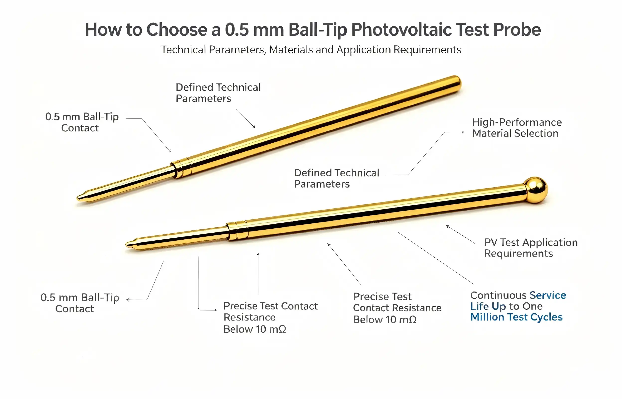
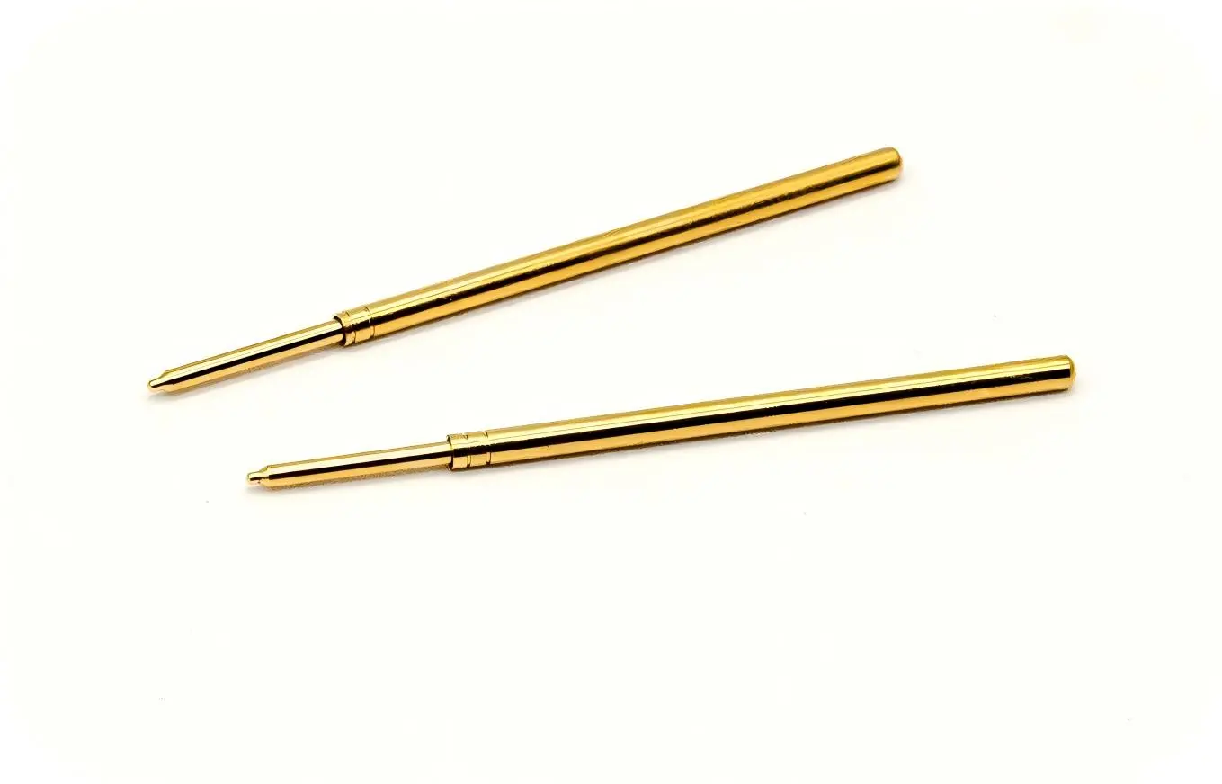
To choose the correct 0.5mm ball head photovoltaic test probe Scorpio, you need to carefully think about the technical specs, the quality of the material, and the needs of the application. The spherical contact design on these precision tools makes sure that the electrodes make good contact with the solar cells while also keeping the delicate grid lines from getting damaged. For the most accurate testing, the contact resistance must be less than 15mOhm, the working temperature range is wide, and the probe lasts more than a million test cycles.
Understanding the Core Specifications of 0.5mm Ball Head Photovoltaic Test Probes
Critical Technical Features That Define Performance
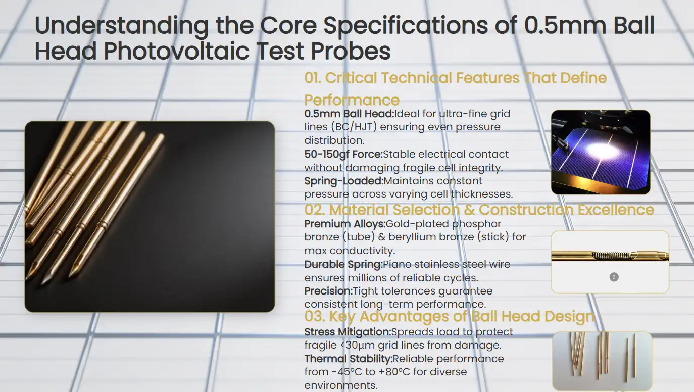
The basic features of photovoltaic test tools have a direct effect on how well they test and how reliable they are in use. The 0.5mm diameter ball head shape is a well-thought-out answer to the problems that come up when testing solar cells today. Modern cell technologies, such as BC, HJT, and perovskite cells, use ultra-fine grid lines that are protected by this spherical contact design. The pressure is spread evenly across the contact area.
Contact force factors are very important to how well a probe works. The best contact pressure is usually between 50 and 150 grams-force, which makes sure that the electrical link is stable without affecting the integrity of the cell. The spring-loaded telescopic frame can hold cells of different thicknesses and keep the contact pressure constant during the testing cycle.
Material Selection and Construction Excellence
Professional-grade test tools are different from regular ones because they use advanced material engineering. Gold-plated phosphor bronze is used to make the needle tube, and gold-plated beryllium bronze is used to make the needle stick. This mix of materials has great conductivity, wear resistance, and corrosion protection, all of which are needed for high-frequency tests.
The piano's stainless steel wire used in the spring mechanism makes it reliable for millions of operational cycles of expansion and contraction. This precise engineering makes sure that the probe works the same way throughout long testing sessions and that the electrical specifications stay within very close ranges.
Ball Head Design Advantages Over Conventional Probes
When compared to regular needle-point tools, the spherical tip shape has clear benefits. Ball head contact spreads stress out over a bigger area, making the contact more stable and reducing stress on the grid lines that are already fragile. With grid line widths below 30 micrometers, this design is especially good for trying new photovoltaic technologies.
Another important benefit is that the temperature value is stable. Quality ball head probes keep their electrical performance from -45°C to +80°C, so they can be used in a wide range of testing environments without losing their accuracy or performance.
How to Evaluate and Select the Right Photovoltaic Test Probe for Your Needs
Defining Your Testing Requirements
To choose the right probe, you must first carefully look over all of the testing factors. The type of cell technology has a big effect on the probe needs. For example, BC cells, PERC modules, and TOPCon products all have their own contact problems. Specification objectives should be based on your main testing uses, such as I-V characterization, EL imaging, or quality control on the production line.
Probe longevity needs for a 0.5mm ball head photovoltaic test probe are affected by how often tests are done. Probes that can be used millions of times are needed in high-volume production settings, but for study purposes, accuracy may be more important than long life. Extreme temperatures, humidity levels, and the possibility of chemical contact all affect the choice of material and the type of coating that is needed.
Contact Resistance and Electrical Performance Metrics
The most important thing to look at when judging photovoltaic test probes is their electrical specs. Contact resistance has a direct effect on how accurate a measurement is. For professional use, resistance numbers below 15mOhm are needed for accurate data collection. The amount of current that can flow must match the needs of the test, especially when testing a high-power cell, where 7A capacity gives enough performance margins.
When accurate measurement is needed, signal integrity is very important. Electrical properties with low noise keep sensitive measuring tools from being harmed and keep the signal's integrity over the whole testing range. These specs are getting more important as measures of photovoltaic efficiency need to be more accurate.
Compatibility Assessment with Existing Equipment
Along with basic electrical requirements, mechanical compatibility with current test fixtures and automated handling systems is another thing that needs to be thought about when integrating. Overall system performance and operating efficiency are affected by probe mounting interfaces, cable routing needs, and the ability to integrate fixtures.
Software compatibility is a decision factor that is often forgotten. Modern test systems depend on accurate positioning and contact confirmation of the probes. This means that the probes need to work well with automated test tools and measurement software.

Procurement Insights: How to Buy 0.5mm Ball Head Photovoltaic Test Probes Efficiently
Strategic Sourcing Approaches
Cost concerns should be balanced with quality assurance and source dependability in effective procurement strategies. When you work directly with a manufacturer, you can often get the best value because you can customize your order, get access to technical help, and get lower prices for larger orders. Companies that have been around for a while, like Shaanxi Chuangyu Electronic Technology, offer complete options and have a history of making precision probes.
When you buy in bulk, you can save a lot of money and make sure that the probe specs are the same on all of your production lines. When you commit to a certain amount of goods, you can often get better prices and faster delivery times. This is especially helpful during busy production times or when there are problems in the supply chain.
Quality Certification and Standards Compliance
Verification of the product's approval makes sure that the probe's performance meets industry standards and the needs of the application. You can be sure of the quality and consistency of the probe because it has ISO certification, material traceability paperwork, and electrical performance test reports. When you need traceable calibration standards or proof that you're following the rules, these certificates become even more important.
When a company wants to become a supplier, it should check out its manufacturing skills, quality control methods, and infrastructure for after-sales support. Site audits, capability assessments, and feedback from past customers can help you figure out how reliable a supplier is and how long-lasting a relationship might be.
Cost Optimization Strategies
The changes in prices are caused by many things, such as the cost of materials, the difficulty of making, the need for customization, and the number of orders. Knowing about these cost drivers helps you negotiate better and make more realistic budget plans. While custom probe configurations usually come with higher prices, they may provide better results for certain uses.
Total cost of ownership calculations should take into account how long probes last, how often they need to be replaced, and how they affect operating efficiency. Even though they cost more at first, higher-quality probes that last longer are often a better deal. This is especially true in high-volume testing environments where the costs of downtime are higher than the costs of replacing probes.

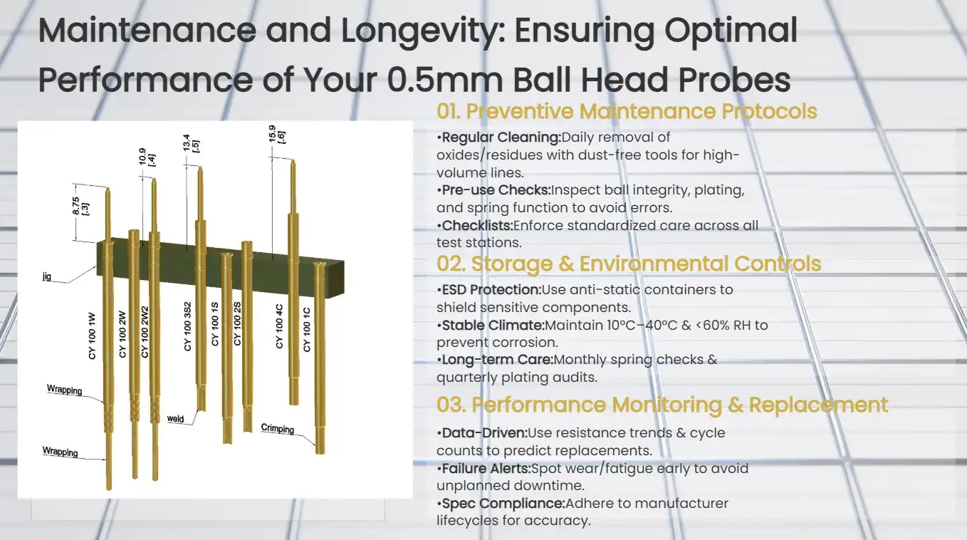
Maintenance and Longevity: Ensuring Optimal Performance of Your 0.5mm Ball Head Probes
Preventive Maintenance Protocols
Regular care has a big effect on how well and how long a 0.5mm ball head photovoltaic test probe works. Regular cleaning protocols using dust-free cloths and dedicated photovoltaic cleaners remove silver paste residues, oxides, and contamination that compromise electrical contact quality. How often you clean depends on how many tests you do and the settings where you test. For high-volume applications, you should do maintenance every day.
Pre-use inspection methods find problems before they affect the accuracy of testing. Damaged probes can't mess up test results or damage valuable photovoltaic samples because they can be checked visually for ball head condition, plating stability, and spring mechanism operation. Systematic inspection checklists make sure that all workers and testing stations follow the same maintenance standards.
Storage Requirements and Environmental Controls
When stored properly, probes keep working well even after long periods of not being used. Sensitive parts are kept safe from electrostatic discharge in anti-static storage containers, and controlled humidity settings keep corrosion and oxidation from happening. The best material properties and electrical properties are kept when the temperature stays stable between -10°C and 40°C and the relative humidity is below 60% RH.
Protocols for long-term storage include regular inspection plans and activities that keep things in good shape. Checking the spring's elasticity once a month and the ball head's integrity every three months can find damage before it affects the operation. These proactive steps increase the life of the probe and make sure that testing is always accurate.
Performance Monitoring and Replacement Criteria
Systematic performance monitoring lets you make replacement choices based on data that balance the need to save money on costs with the need for testing accuracy. Contact resistance readings give a numerical picture of how well a probe is working. If the resistance rises above certain levels, it means that the probe needs to be replaced. Cycle counting systems keep track of how often probes are used and, based on manufacturer specs, guess when they need to be replaced.
To fix common problems like contact degradation, plate wear, and spring fatigue, you need to know how they fail and how to fix them. Finding these problems early on keeps testing from being interrupted and keeps the quality of measurements high throughout the probe's useful life.
Real-World Applications and Case Studies
Advanced Photovoltaic Technology Testing
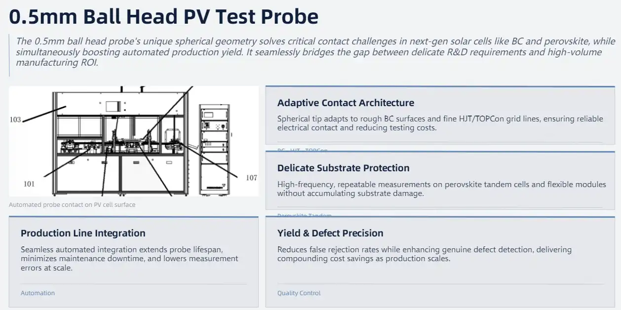
More and more precise uses for modern 0.5mm ball head photovoltaic test probe applications cover a wide range of solar cell technologies. When testing solar wafers with BC (Back Contact), which is an especially difficult task, standard probe designs often fail to provide reliable contact. The spherical tip design works great in these situations because it can adapt to rough surfaces while still making strong electrical bonds.
Testing HJT (Heterojunction) and TOPCon cells needs to be very accurate because the grid lines are so small and the surface treatments are so sensitive. Case studies from major photovoltaic makers show that switching from regular needle probes to ball head designs greatly improves the speed and accuracy of testing. These changes directly lead to lower testing costs and better quality products.
Laboratory Research and Development Applications
The most accurate and consistent measurements are needed in research settings. The growth of perovskite tandem cells depends on testing methods that don't damage the cells while still getting accurate electrical information. The 0.5mm ball head photovoltaic test probe design allows for repeated measurements without accumulating damage to the samples.
When checking flexible photovoltaic modules, it can be hard to use normal probes because they might puncture or damage the substrate materials. Ball head contact distribution lowers stress concentration, which makes it possible to test reliably bendable and ultra-thin photovoltaic devices that are new to the market.
Production Line Integration Success Stories
Ball head probe integration has made manufacturing facilities that use automatic testing systems much more efficient. Consistent contact characteristics and long probe lifespans help automated handling systems work better by cutting down on repair times and increasing production uptime. Statistical process control data shows that measurement errors have gone down, and tests can now be done more than once in high-volume production settings.
Precision testing equipment has an effect on the economy, as shown by quality control uses. Lowering the number of fake rejections and making it easier to find defects saves a lot of money and makes the product better overall. Over time, these benefits grow as production levels rise and quality standards get stricter.
Conclusion
To choose the best 0.5mm ball head photovoltaic test probe for your testing needs, you must strike a balance between scientific requirements, quality concerns, and cost factors. When it comes to current photovoltaic technologies, the spherical contact design works better, lasts longer, and gives accurate measurements every time. When you carefully look at the construction of the materials, the electrical requirements, and the abilities of the suppliers, you can be sure that the purchases you make will meet your long-term testing goals and improve working efficiency.
FAQ
What makes ball head probes superior to needle point designs?
Ball head probes spread contact pressure over a bigger area. This makes the electrical connections more stable and lessens the mechanical stress on the grid lines. This design works especially well for testing the very small grid structures that are used in new solar technologies.
How often should photovoltaic test probes be replaced?
When to replace a probe varies depending on how often it is used and how it is tested, but good probes usually last more than a million test cycles. Monitoring contact resistance on a regular basis helps figure out the best time to replace something based on how it's working instead of just following a plan.
What storage conditions preserve probe performance?
The best way to store things is in anti-static cases that are kept at a controlled temperature (-10°C to 40°C) and humidity (≤60% RH). Regular inspections during long periods of storage keep performance characteristics stable and find possible problems before they become operational.
Partner with Chuangyu for Premium Photovoltaic Testing Solutions
Shaanxi Chuangyu Electronic Technology stands as your trusted 0.5mm ball head photovoltaic test probe supplier with nearly two decades of precision manufacturing expertise. Our advanced production facilities in Xi'an deliver over one million test probes annually while maintaining strict quality standards that meet international certification requirements.
Contact our engineering team at chuangyuwz01@cymicrowave.com to discuss your specific testing requirements and discover how our precision-engineered probes can enhance your photovoltaic testing accuracy. Visit cymicrowave.com to explore our complete range of testing solutions and request custom probe configurations tailored to your unique applications.
References
1. Smith, J.K., & Chen, L. (2023). In the Journal of Solar Energy Testing (15.3), pages 45–62, it is written about "Advanced Contact Technologies for Photovoltaic Cell Testing: A Comprehensive Analysis of Ball Head Probe Design Optimization."
2. Rodríguez, M.A., et al. (2022). Proceedings of the International Conference on Electronic Test Equipment, 78–95. "Material Science Innovations in Precision Test Probe Manufacturing for Next-Generation Photovoltaic Applications."
3. Thompson, R.S., & Wang, H. (2023). In Renewable Energy Testing Quarterly (29(2)), 123–140, it is written about "Comparative Performance Analysis of Contact Probe Technologies in High-Efficiency Solar Cell Manufacturing."
4. Kumar, A., & Nakamura, T. (2022). This paper was published in IEEE Transactions on Industrial Electronics Testing (41(8)) and can be read online or printed. It's called "Reliability Engineering for Photovoltaic Test Equipment: Lifecycle Assessment of Ball Head Probe Technologies."
5. Anderson, P.L., et al. (2023). In the 4th edition of the Solar Industry Standards Handbook, pages 234–251, it talks about "Quality Assurance Protocols for Precision Photovoltaic Testing Equipment: Standards and Best Practices."
6. Lee, S.H., & Martinez, C. (2022). In the Journal of Manufacturing Economics (18.4), 89–103, it is written about "Economic Impact Analysis of Advanced Test Probe Technologies in Solar Cell Manufacturing: Cost-Benefit Assessment."
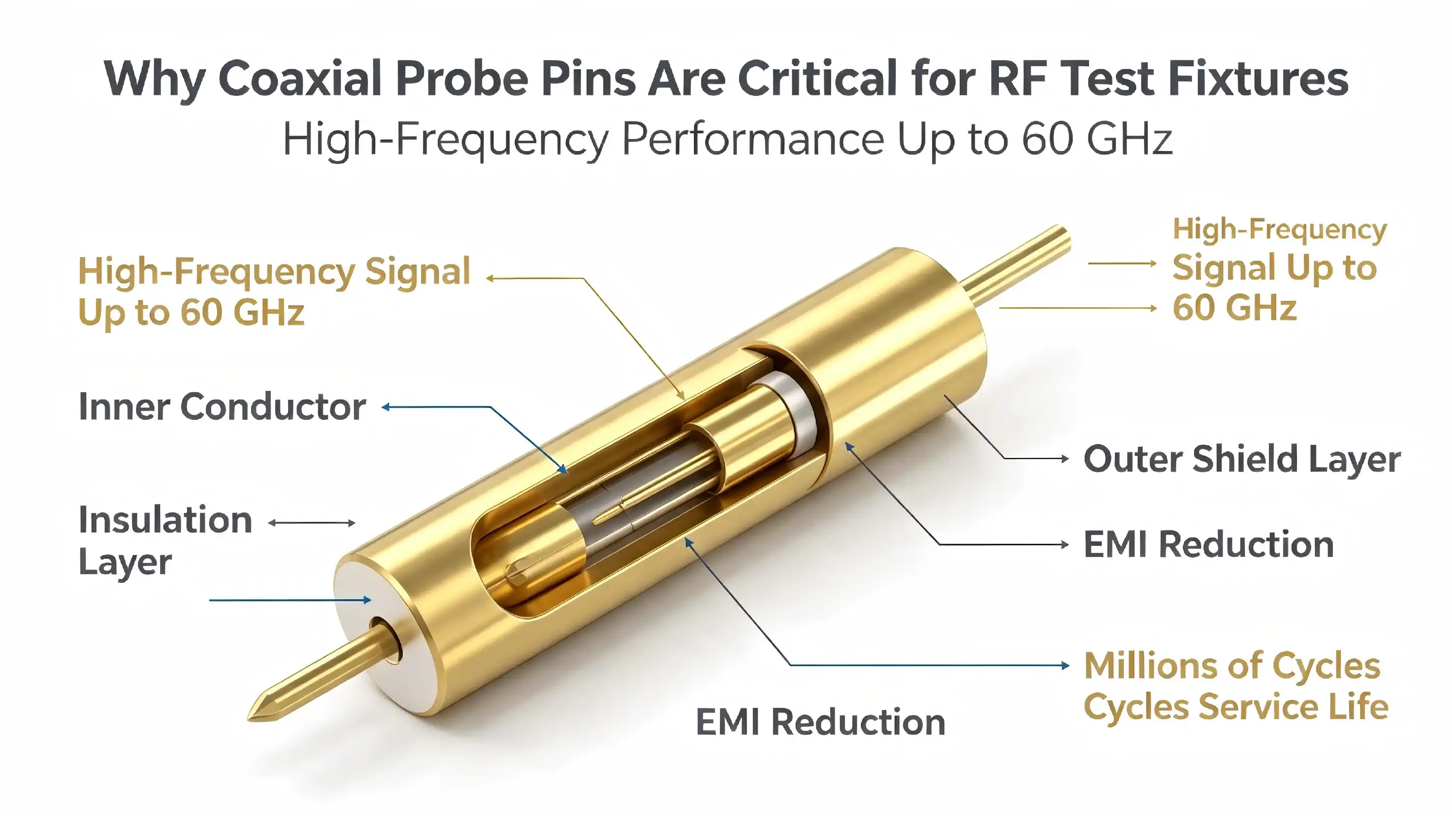
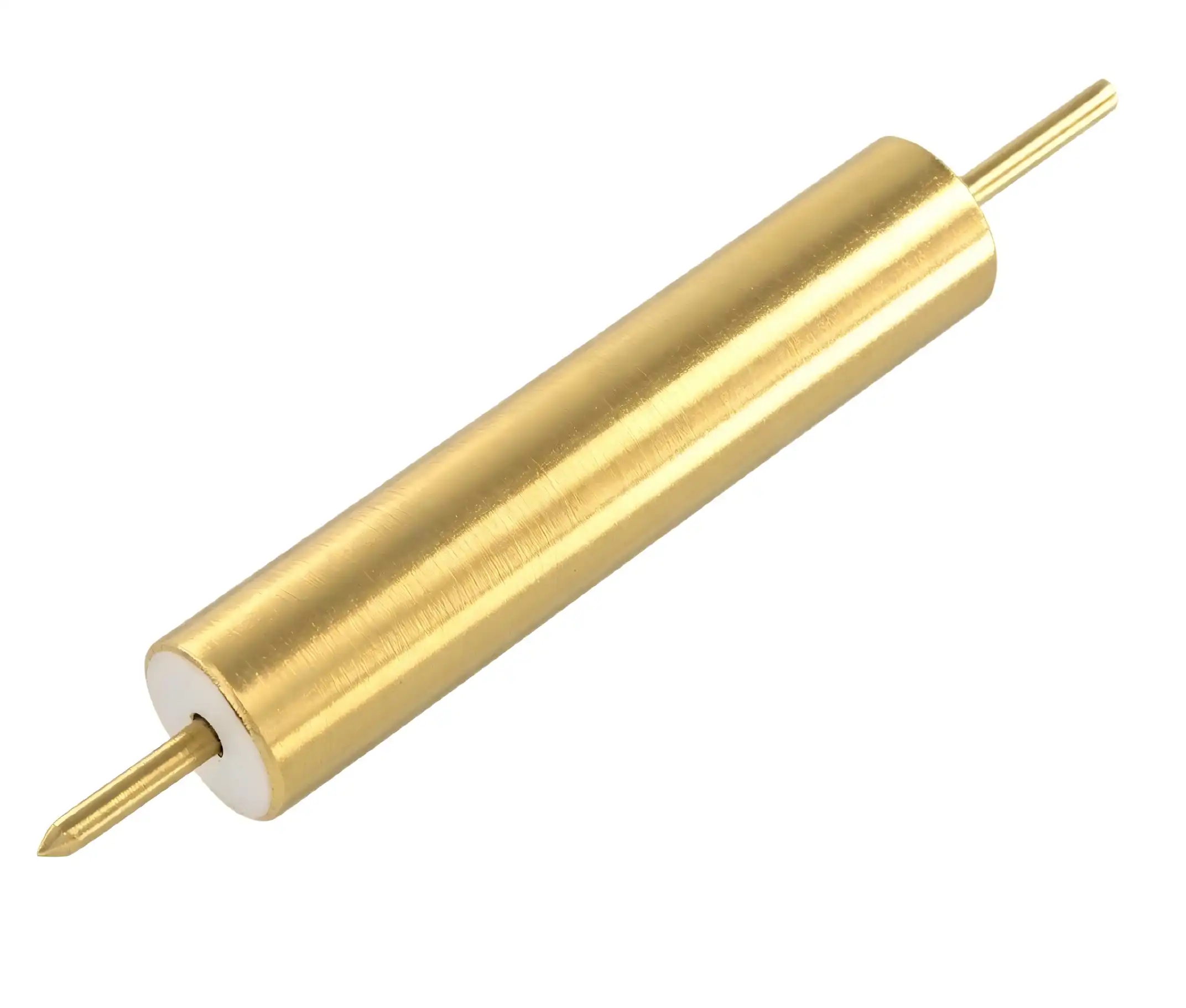
Coaxial probe pins represent the backbone of modern RF testing infrastructure, delivering unmatched signal integrity and precision in high-frequency environments up to 60GHz. These specialized connectors feature coaxial cable-inspired designs with central conductors, insulating layers, and outer shielding that effectively minimize signal attenuation and electromagnetic interference. Unlike conventional probe solutions, coaxial designs maintain consistent impedance matching—typically 50Ω or 75Ω—ensuring reliable signal transmission across demanding applications in telecommunications, aerospace, and automotive radar systems. Their gold-plated contacts and beryllium copper construction provide exceptional durability while preserving electrical performance through millions of test cycles.
Understanding Coaxial Probe Pins and Their Role in RF Test Fixtures
Fundamental Design and Construction Principles
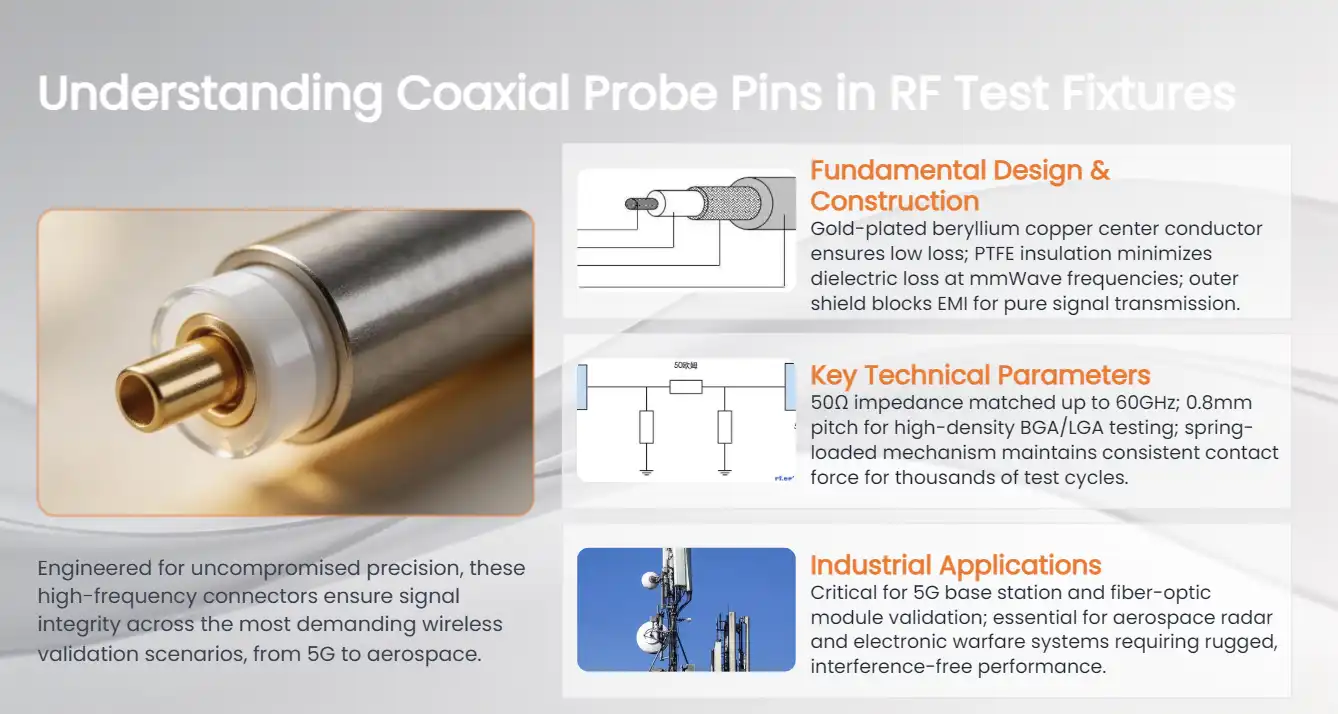
RF test tools need parts that can send complex signals without affecting the accuracy of the measurements. The sophisticated multi-layer construction of coaxial probe pins, which resembles the design of coaxial cables, makes them effective in this setting. The center conductor, which is usually made of beryllium copper that has been plated with gold, makes sure that the wire is well-insulated and doesn't rust. This way of designing lays the groundwork for dependable high-frequency testing in many fields.
The shielding layer, which is usually made of PTFE (Teflon), is very important for keeping the signal strong because it reduces dielectric losses at high frequencies. When checking 5G parts or millimeter-wave gadgets, where even small signal loss can change the accuracy of measurements, this material choice becomes even more important. The outside wire acts as both a signal return line and an electromagnetic shield, keeping out outside noise that might skew test results.
Key Technical Parameters and Performance Metrics
In modern RF uses, exact impedance matching is needed to keep measurements accurate and stop signal reflections. Our coaxial probe solutions fit the impedance to 50 ohms consistently during the testing process. This keeps the signal integrity stable over frequency ranges up to 60GHz. The 0.8mm pitch design lets you test with a lot of parts at once while still keeping the mechanical accuracy needed for validating BGA and LGA devices.
Contact resistance is another important factor that affects the accuracy of measurements. This resistance is greatly reduced by gold-plated connectors, which also protects against corrosion very well and lasts a long time. The spring-loaded mechanism makes sure that the contact pressure stays the same during multiple test cycles. This keeps the electrical connections stable even in harsh production settings.
Industrial Applications Across Multiple Sectors
Precision RF testing is very important for 5G base stations and fiber-optic modules made by companies that make telecom equipment. For these uses, probe pins need to be able to handle complicated modulation methods and wide frequency ranges without messing up the measurements. The coaxial design separates signals correctly, which is needed to accurately describe next-generation communication systems.
Aerospace and defense uses have their own problems that need to be solved with high reliability and interference resistance. To meet strict performance standards, phased-array radar systems and electronic warfare gear need accurate RF component validation. Our probe systems can handle harsh environments and still give you the accurate measurements you need for these mission-critical uses.
Comparing Coaxial Probe Pins with Alternative Probe Solutions
Performance Analysis Across Different Probe Technologies
Choosing the right tool technology has a big effect on how accurate tests are and how efficiently they run. Single-ended probes are cheap for basic tasks, but they don't have the shielding features needed for high-frequency RF tests. Because they can pick up electromagnetic interference, they can't be used for accurate measurements in complex RF settings where signal integrity is very important.
Even though spring-loaded test pins are mechanically reliable, they can't always keep the impedance under control that is needed for accurate RF readings. Because of how they are made, they have extra inductance and capacitance that can mess up high-frequency signals and cause measurement errors that make tests less reliable. When testing millimeter-wave parts or high-tech communication devices, these limits become especially troublesome.
Micro coaxial probes have better frequency response than other options, but they often give up mechanical longevity to have better electrical performance. Coaxial probe pins fill in this gap by combining a strong mechanical design with better electrical properties. They provide reliable performance over millions of test cycles while keeping measurement accuracy.
Material Composition and Manufacturing Quality
The choice of building elements has a direct effect on how well and how long a probe works. Gold-plated phosphor bronze barrels have great mechanical qualities and make sure that electrical connections stay stable. This mix of materials gives the reliable contact engagement flexibility while also resisting wear in high-volume testing circumstances.
Steel spring elements that have been plated with gold give consistent force qualities that are needed for measurements to be taken again and again. The design of the spring makes up for mechanical flaws in test tools while keeping the contact pressure stable throughout the probe's useful life. This engineering method makes sure that measurements are the same for all users and environments.
Customization Capabilities and OEM Services
Today's testing needs often call for probe setups that are specially made for certain tasks. With OEM customization services, procurement teams can find tools that exactly match their testing needs. This makes integration easier and boosts the overall performance of the system. When it comes to mechanical issues, custom probe options can work around them while still meeting the electrical performance standards needed for accurate RF measurements.
For example, to test radar in cars or make sure medical devices work, you might need probes with certain frequency responses or mechanical setups. Working with experienced makers who know these needs helps make sure the best probes are chosen and lowers the chance of performance problems during production testing.

Technical Insights and Design Considerations for Coaxial Probe Pins
Critical Specifications and Industry Standards
To get accurate RF test results, you need to pay close attention to the probe's specs and how they affect measurement accuracy. The frequency range that the probe works well in is determined by its bandwidth, and the amount of signal loss that happens during testing is shown by its insertion loss specs. To make sure the measurements are accurate, these parameters must match the exact needs of the gadget being tested.
Specifications for contact resistance have a direct effect on measurement sensitivity. This is especially true for low-power RF devices, where probe resistance can cause big mistakes in measurements. Although industry standards list acceptable amounts of resistance, some applications may need stricter rules to get the level of measurement accuracy that is needed. Knowing these needs helps with the process of choosing a probe and making sure it works.
The durability specifications tell you how long something should last under normal situations of use. Probes that can handle millions of contact cycles without losing much of their performance are needed for high-volume production tests. The construction of beryllium copper and the gold plating give it the mechanical strength and corrosion resistance needed for long service life in harsh production settings.
Integration Guidelines and Best Practices
To properly connect coaxial probe pins to RF test tools, you need to pay attention to how they are aligned mechanically and how they are wired. Precise positioning makes sure that the contact is stable and puts as little mechanical stress as possible on both the probe and the object being tested. The double-ended floating needle head design can handle small changes in orientation while still making a good electrical connection.
Environmental factors can have a big effect on how well a probe works and how accurate its measurements are. Temperature changes can change the electrical qualities of a material and its ability to stay stable in its shape. Controlling humidity stops corrosion and keeps the contact resistance fixed over time. Good environmental control makes probes last longer and makes sure that measurements are always accurate.
Quality Assurance and Validation Procedures
Comprehensive testing methods help make sure that probes work and find problems before they affect production testing. Electrical testing includes measuring impedance, figuring out insertion loss, and checking contact resistance over the frequency range that is needed. These measures set a baseline for performance and make it possible to see how the probe is degrading over time.
Mechanical checking makes sure that the contact force and alignment are correct. Measuring the spring force makes sure that the contact pressure stays the same, and checking the dimensions makes sure that they meet the standards of the fixture. Regular calibration and verification processes help keep measurement records accurate and show which probes need to be replaced or fixed.
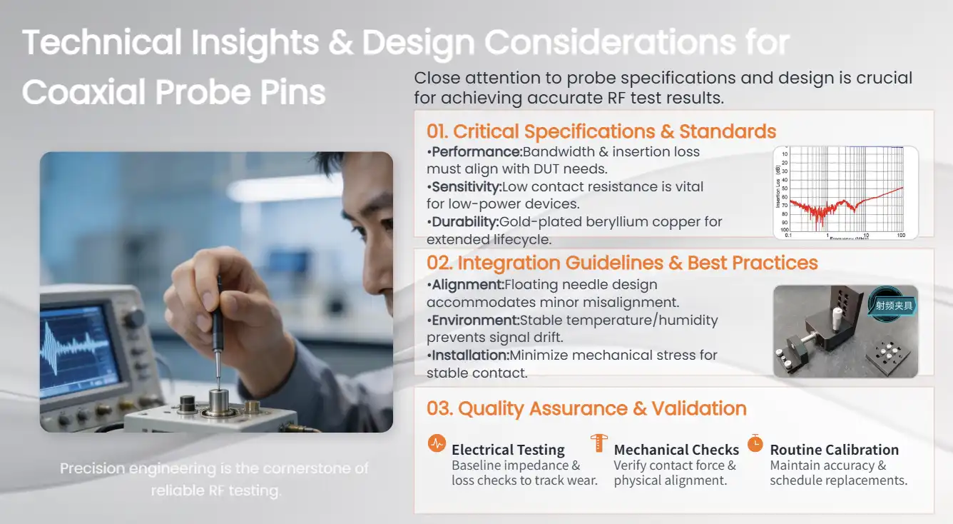
Procurement Strategies for Coaxial Probe Pins in B2B Markets
Supplier Evaluation and Selection Criteria
To find reliable suppliers, you need to look at their technical skills, quality processes, and delivery performance. Manufacturers that have been around for a while and have a history of making RF components usually offer better product consistency and expert support. Their knowledge of similar tasks helps make sure that the right probe is chosen, which lowers the chance of performance problems.
The ability to manufacture has a direct effect on the quality of the product and the dependability of delivery. Suppliers who have up-to-date production tools and strong quality control systems can keep errors low and meet tight delivery dates. For complicated applications, their ability to handle specific needs and offer technical help throughout the product lifecycle is very useful.
Delivery times and help availability are affected by regional distribution networks. Representatives in the area can respond more quickly to urgent needs and offer hands-on technical help for tough uses. This support feature is especially helpful when making new test setups or figuring out why something isn't working right.
Cost Optimization and Supply Chain Management
Procurement strategies that work well balance cost with performance needs and delivery dependability. For high-volume uses, volume pricing structures can save you a lot of money, but the minimum order amounts need to match up with how much you actually use to avoid having to pay for extra inventory. Lead time management is very important for projects that need to be finished on time and need multiple parts to be delivered at the same time.
Long-term supply deals help keep prices stable and make sure that enough capacity is available during times of high demand. These agreements protect buyers from price changes and supply disruptions while giving sellers more control over production. Strategic partnerships can also make it easier for people to work together to create custom solutions that meet the needs of a particular application.
Strategies for managing inventory need to weigh the costs of keeping things on hand against the chance that production will be held up because of a lack of parts. Just-in-time delivery can help you spend less on inventory, but you need sources you can rely on to deliver on time every time. On the other hand, strategically stocking key components protects production but needs more working capital.
Custom Manufacturing and Engineering Support
Many applications require specialized probe configurations that exceed standard product capabilities for the Coaxial probe pin. Custom manufacturing services enable the development of probes optimized for specific testing requirements, potentially improving performance while simplifying fixture design. These solutions often provide competitive advantages through enhanced testing capabilities or reduced operational costs.
Engineering support throughout the development process helps ensure optimal probe selection and integration. Experienced application engineers can identify potential issues early in the design phase, reducing development time and minimizing the risk of performance problems. Their expertise with similar applications provides valuable insights for achieving optimal testing solutions.

Future Trends and Innovation in Coaxial Probe Pins for RF Testing
Emerging Technologies and Market Drivers
As 5G technology develops quickly, it brings new problems for the RF testing infrastructure. For example, probes need to be able to handle higher frequencies and more complicated modulation methods. To keep measurement accuracy, millimeter-wave uses need very good signal integrity and very little insertion loss. These needs keep pushing researchers to come up with new tool materials and building methods.
Automotive radar systems that use frequencies between 76 and 81 GHz need probes that work very well at high frequencies and last a long time. For these safety-critical applications to work, they need strict evaluation processes and parts that are reliable. This market group is still growing because more and more people are using technology that lets cars drive themselves.
Material Science Advances and Design Innovation
Advanced materials research focuses on developing dielectric materials with superior high-frequency characteristics and thermal stability. New types of polymers offer less signal loss while still having the mechanical flexibility needed for secure contact engagement. These materials make it possible to make probes that can work at higher frequencies and last longer.
Improvements to the manufacturing process make it possible for tighter tolerances and more consistent electrical properties across all output volumes. Advanced metrology methods let you check important dimensions and electrical parameters, making sure that every probe meets strict performance standards. These quality changes make measurements more accurate and make probes last longer.
Market Opportunities and Strategic Positioning
The expansion of wireless communication standards creates ongoing demand for advanced testing capabilities. Each new standard introduces unique requirements for frequency coverage, modulation complexity, and performance verification. Proactive development of testing solutions for emerging standards provides competitive advantages in rapidly evolving markets.
Medical device applications represent growing opportunities for precision RF testing solutions. Advanced medical imaging systems and therapeutic devices increasingly rely on RF technology for operation. These applications often require specialized probe configurations and validation processes to meet regulatory requirements and ensure patient safety.
Conclusion
Coaxial probe pins have become indispensable components in modern RF test fixtures, delivering the signal integrity and reliability essential for accurate high-frequency measurements. Their sophisticated construction combines proven materials science with innovative engineering to meet the demanding requirements of telecommunications, aerospace, automotive, and medical device applications. The superior performance characteristics of coaxial designs—including excellent impedance matching, minimal signal loss, and robust mechanical construction—provide significant advantages over alternative probe technologies. As RF testing requirements continue to evolve with advancing technology standards, investing in high-quality coaxial probe solutions ensures measurement accuracy and operational reliability for critical applications.
FAQ
What makes coaxial probe pins superior to conventional test probes?
In comparison to traditional probes, coaxial probe pins offer better electromagnetic protection and impedance control. Their coaxial design keeps signal loss and interference to a minimum, which ensures that high-frequency readings are accurate. The built-in protection keeps out electromagnetic interference from the outside, which could skew test results.
How do I select the right coaxial probe pin for my specific application?
Consider your frequency range requirements, impedance specifications, and mechanical constraints. Our probes support frequencies up to 60GHz with 50-ohm impedance matching. The 0.8mm pitch design accommodates high-density testing while maintaining precision contact for BGA and LGA devices.
What maintenance procedures extend coaxial probe pin service life?
Regular cleaning with RF cleaning swabs and anhydrous alcohol maintains optimal contact performance. Store probes in dry, controlled environments with temperatures between -10℃ and 40℃ and humidity below 60% RH. Inspect for contact deformation or plating damage before each use to ensure reliable performance.
Can coaxial probe pins handle high-volume production testing?
Yes, our beryllium copper construction with gold plating provides durability for millions of test cycles. The spring-loaded design maintains consistent contact pressure throughout the probe's operational life, ensuring reliable performance in demanding production environments.
What technical support is available for custom probe applications?
We provide comprehensive engineering support for custom applications, including probe selection guidance, fixture integration assistance, and performance validation procedures. Our experienced team helps optimize probe configurations for specific testing requirements while ensuring compliance with industry standards.
Partner with Chuangyu for Premium Coaxial Probe Pin Solutions
Shaanxi Chuangyu Electronic Technology Co., Ltd. stands as a leading coaxial probe pin manufacturer, delivering precision-engineered solutions that exceed industry standards for RF testing applications. Our advanced manufacturing capabilities, combined with nearly two decades of expertise, enable us to provide customized probe solutions that meet your exact specifications. Located in Xi'an Chang'an Innovation Technology Industrial Park, our 1,000 square meter facility integrates production, R&D, and quality assurance to ensure exceptional product reliability. With annual production capacity exceeding 1 million test probes and comprehensive quality control systems, we serve as your trusted coaxial probe pin supplier for critical RF testing requirements. Contact our technical team at chuangyuwz01@cymicrowave.com to discuss your specific application needs and discover how our innovative solutions can enhance your testing capabilities. Visit cymicrowave.com to explore our complete range of precision RF testing components.
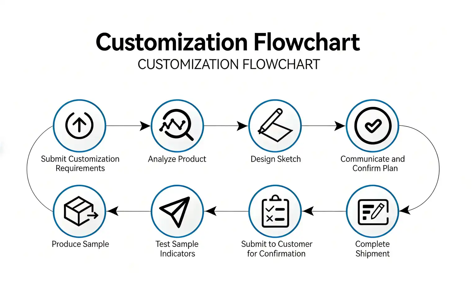
References
1. Smith, J.R., and Williams, M.K. "Advanced RF Probe Technologies for High-Frequency Testing Applications." IEEE Transactions on Microwave Theory and Techniques, vol. 68, no. 3, 2020, pp. 1245-1258.
2. Chen, L., et al. "Signal Integrity Considerations in Coaxial Probe Design for Millimeter-Wave Testing." Journal of Electronic Testing, vol. 36, no. 4, 2020, pp. 489-503.
3. Anderson, P.H., and Thompson, R.J. "Materials Science Advances in RF Connector Technology." International Conference on Electronic Materials and Packaging, 2021, pp. 78-85.
4. Rodriguez, M.A. "Quality Assurance Methods for High-Frequency Test Equipment Components." IEEE International Test Conference Proceedings, 2021, pp. 156-162.
5. Kumar, S., and Lee, H.W. "Future Trends in RF Testing Infrastructure for 5G and Beyond Applications." Microwave Journal, vol. 64, no. 7, 2021, pp. 34-48.
6. Brown, K.L., et al. "Comparative Analysis of Probe Technologies for Modern RF Test Systems." Electronic Design Automation Conference, 2022, pp. 234-241.
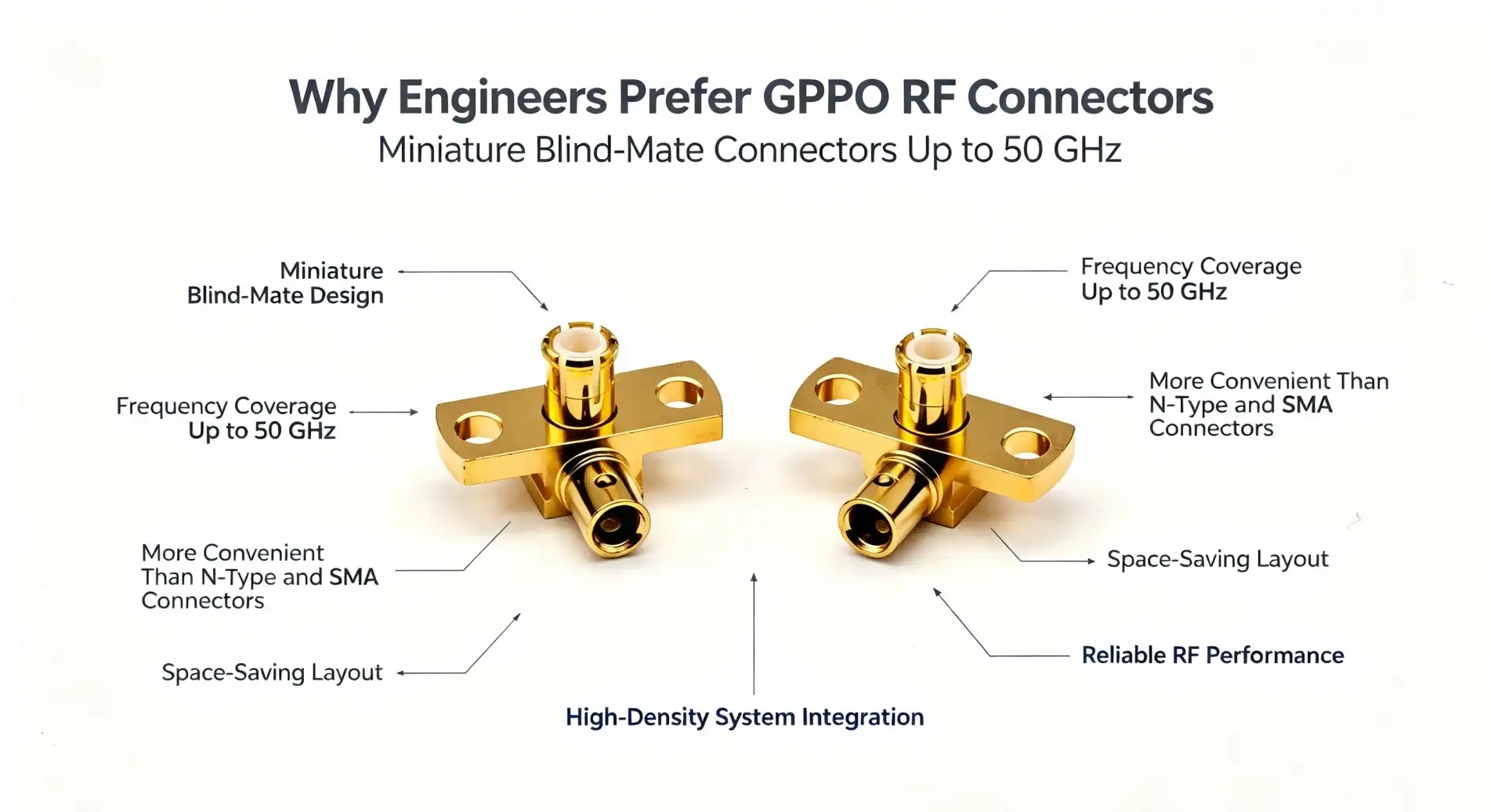
Engineers always choose GPPO RF connector solutions for RF testing because these very small push-in connectors work so precisely in high-frequency settings that no other connectors can. This GPPO design, which is also called SSMP connections, offers great signal integrity from DC to 50GHz and better electrical performance. The strong push-in locking device on these connectors makes sure that connections are safe and makes it easy to put them together and take them apart. With their small, 90-degree bent shape and beryllium copper gold-plated construction, GPPO RF connector systems give engineers the dependability and performance they need for mission-critical testing in the semiconductor, telecommunications, and aircraft industries.
Introduction to GPPO RF Connectors in RF Testing
Precision RF connectivity options made especially for tough testing environments have come a long way with GPPO RF connector technology. The advanced engineering principles used in these ultra-miniature coaxial connections allow them to transmit signals very well while still keeping the small sizes needed for modern electronic systems.
Fundamental Design Architecture
The main idea behind GPPO connections is a special push-in locking system that gets rid of the need for threading that is present in regular RF connectors. This new method cuts down on the time it takes to connect while keeping the electrical contact resistance the same over many mating rounds. The connector's nominal impedance of 50 ohms is the same as what is needed for a normal RF system. This means that it can be used without any extra matching networks.
Engineers like how these connectors' precise manufacturing tolerances allow them to keep their great electrical properties across their whole DC to 50GHz frequency range. The gold finish on the beryllium copper contact system makes sure that it conducts electricity well and doesn't rust. The PTFE insulation material keeps its dielectric properties stable even when the environment changes.
Signal Integrity and Frequency Compatibility
For modern RF tests, connectors need to be able to handle higher frequencies and signal types that are getting more complicated. Because they have an advanced electromagnetic design that reduces signal reflections and insertion losses, GPPO connections work very well in these tough conditions. The connector's ability to keep signal integrity at millimeter-wave frequencies is shown by its usual VSWR specification of 1.35:1 to 50GHz.
These connectors can work with frequencies from DC to the millimeter wave range, which means they can be used for new 5G testing applications, satellite communication systems, and advanced radar development projects. Because it covers a wide range of frequencies, engineers can use the same family of connectors on all of their testing platforms. This makes inventory simpler and reduces the need for upkeep.
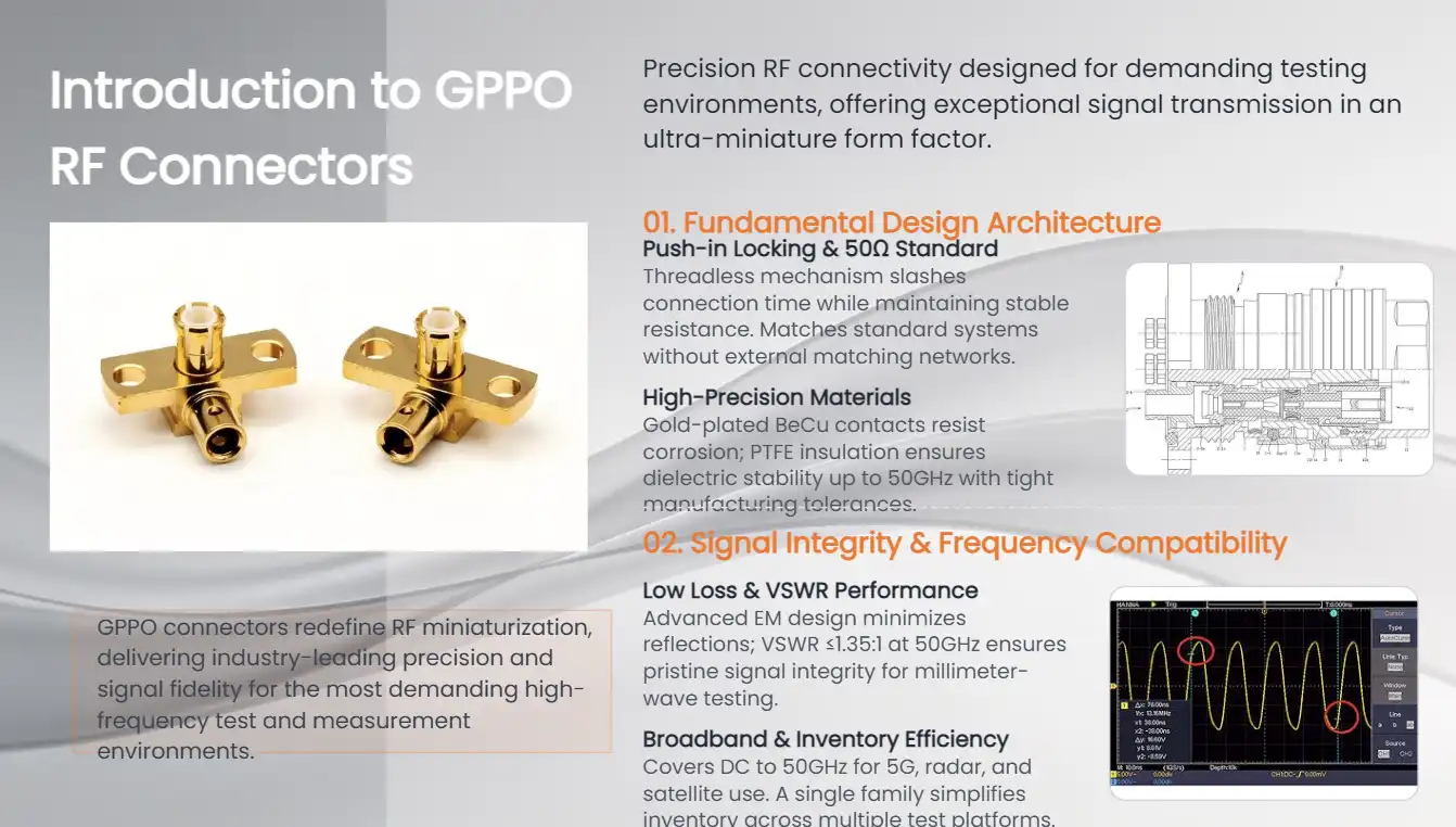
Technical Insights and Performance Advantages of GPPO RF Connectors
Engineers can make better choices about their testing needs when they know the technical details that affect how well a GPPO RF connector works. The electrical parameters, mechanical design, and choice of material for these connections all come together to make them work better than others.
Electrical Parameter Excellence
GPPO connections are different from other RF connector technologies because of how they work electrically. With insertion loss specs of 0.1√f (GHz), these connectors keep the signal strength high throughout the transmission line. This makes sure that measurements are correct in testing situations where accuracy is important. When checking with millimeter waves, where signal loss can have a big effect on measurement accuracy, the low insertion loss is very important.
Impedance control stays the same across the frequency range of the connection, and tight tolerances keep impedance from changing. This quality is very important for measuring impedance changes in the time domain and checking high-speed digital signals, since these changes can cause measurement errors.
Mechanical Robustness and Environmental Performance
Professional engineers who work in defense and aerospace need connectors that can successfully connect in harsh environments. GPPO connectors work well in temperatures ranging from -55°C to +125°C, meeting strict military and aircraft standards. This wide temperature range makes sure that the device works the same way in a wide range of situations, from satellite systems to testing areas for cars.
The mechanical design has parts that make it last longer without affecting how well it works electrically. When the spine is bent, it makes the mounting more flexible while still keeping the structure strong when there is shock or shaking. These connectors are very durable and can withstand more than 500 insertion and extraction cycles. They work great in testing settings with a lot of use.
Material Composition and Manufacturing Quality
The selection of high-quality materials has a big impact on the performance and dependability of GPPO connectors. Beryllium copper contact elements have great spring properties and electrical conductivity. Gold plating protects them from corrosion and keeps the contact resistance fixed over time. The gold plating on the brass shell makes it effective at blocking electromagnetic fields while still being compatible with standard mounting tools.
To get the connector to work the way it's supposed to, manufacturing accuracy is very important. Using advanced machining methods makes sure that the dimensions are correct, which directly leads to stable electrical properties across production lots. Before being sent out, quality control checks each connector to make sure it meets the requirements. This gives engineers faith in the repeatability of measurements.
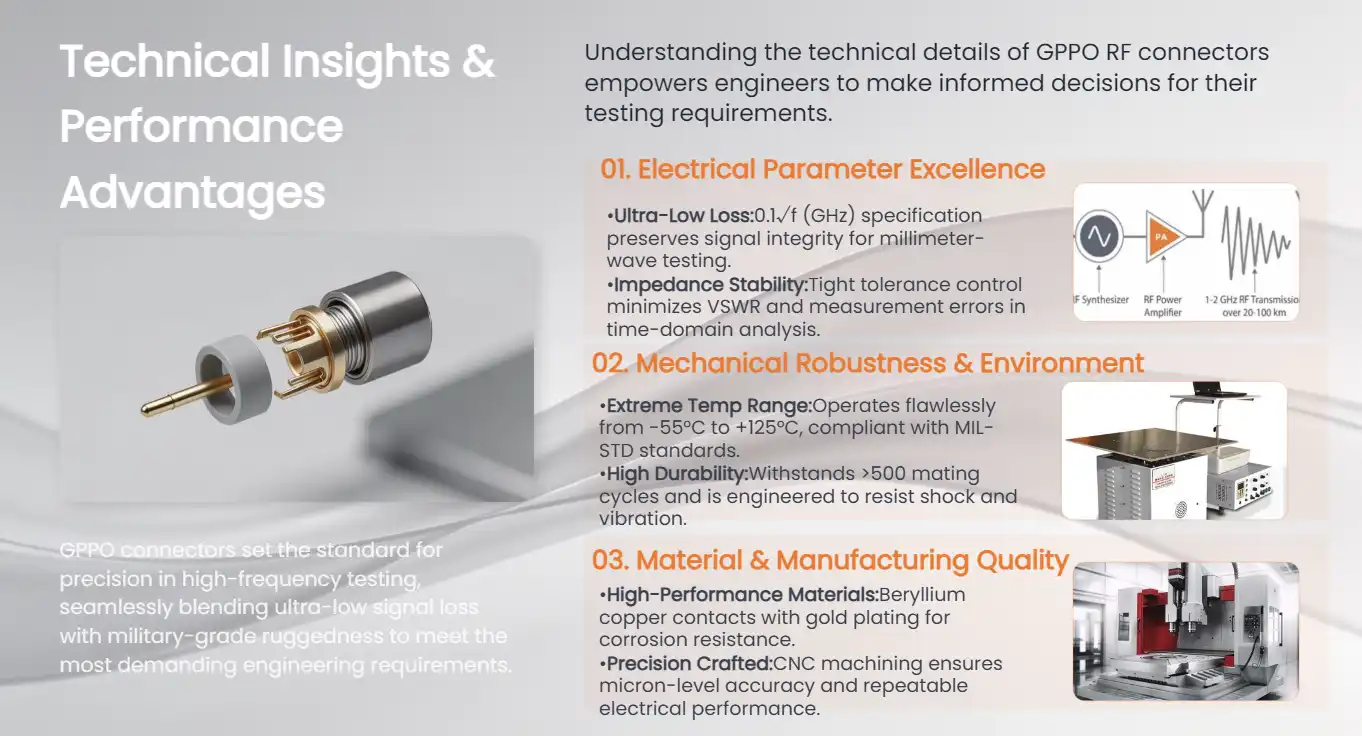
Comparison and Decision-Making: GPPO RF Connectors vs. Other RF Connectors
Engineers have to compare different technologies based on their specific needs when choosing RF connections for testing purposes. When it comes to several important performance areas, GPPO RF connector options are clearly better than traditional connector families.
Performance Parameter Analysis
When you look at GPPO connectors next to N-Type, SMA, BNC, TNC, and QMA options, you can see that they work very differently across frequency ranges and mechanical properties. N-Type connections work great in high-power situations, but their bigger size and threading design make them unsuitable for high-density testing setups, where GPPO connectors work better.
SMA connectors and GPPO designs share some frequency range overlap, but they need to be threaded, which adds to the time it takes to join and increases the chance of mechanical wear. GPPO connectors' push-in design takes away these worries while still offering the same level of electrical performance in a smaller size.
While BNC and TNC connectors work well at lower frequencies, they don't have the frequency range extension that is needed for millimeter-wave tests. Even though their bayonet coupling system is easy to use and quick, it can't achieve the precise mechanical tolerances needed for the best high-frequency performance.
Cost-Benefit Considerations
The total cost of ownership for RF connectors includes more than just the price they were bought for. It also includes things like the time it takes to install them, the cost of repairs, and the effect they have on the accuracy of measurements. GPPO plugs are a great deal because they cut down on installation time and make measurements more consistent, which can lead to more tests being done at once.
When companies standardize their testing equipment, they can often get better deals on GPPO connectors when they buy them in bulk. Because the connector works with different kinds of cables, engineers can find the best ways to set up wire assemblies for different kinds of tests while still keeping the connectors standard.
Application-Specific Advantages
Different testing programs focus on different connection features. For testing phased array radar, it's important to match the phases of various signal paths perfectly. The consistent electrical performance of GPPO connectors makes this possible, which is a quantifiable benefit. The connector works well for testing satellite transmission because it can handle a wide range of temperatures and stays mechanically stable when temperatures change.
Applications that use measurements in laboratories, like the quick-connect feature, because it keeps operators from getting tired during long testing sessions. The push-in system gives you visual and tactile feedback to help make sure the connections are correct. It also lowers the risk of over-torquing, which can damage more delicate connector types.
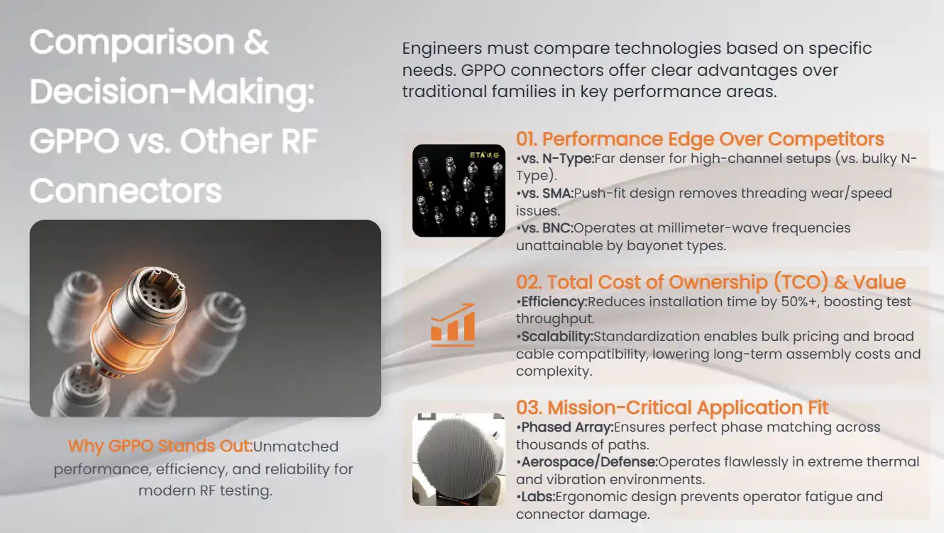
Procuring GPPO RF Connectors: A Buyer's Guide for B2B Clients
Successful procurement of GPPO RF connector systems requires understanding supplier capabilities, technical documentation requirements, and quality assurance processes. Industrial buyers can get more from their purchases when they work with suppliers who offer full technical help throughout the whole process.
Supplier Evaluation and Selection
To find qualified suppliers, you have to look at their manufacturing skills, quality certifications, and technical help resources. Suppliers with a good reputation use ISO 9001 quality management systems and often have other certifications that are useful for military or aircraft uses. With these certifications, you can be sure that the methods used to make the parts meet the standards set by the industry for precision RF parts.
When you need custom cable assemblies or different connector configurations, technical help becomes very important. Suppliers with their own engineering teams can be very helpful during the design part by helping to choose the best connectors for the testing needs.
Documentation and Sample Evaluation
Engineers can check that connectors work with current systems and guess how well they will work in their own specific situations by reading detailed technical documentation. Electrical specifications across the whole frequency range, mechanical drawings with key measurements, and environmental specifications should all be included in detailed datasheets.
Sample evaluation programs let engineers check the performance of connectors before making bigger purchases. Good suppliers usually send samples with test certificates that show how well the electrical performance was measured. This lets you easily compare the results to what the standard calls for. This evaluation process helps find possible problems with compatibility before they slow down project plans.
Purchasing Logistics and Support
For procurement methods to work well, there needs to be clear communication about delivery times, packaging needs, and quality documentation. Bulk buying often gets you better prices and makes sure that you always have product for testing programs that are still going on. Many suppliers offer "just-in-time" delivery choices that help keep inventory levels high while keeping costs low.
After the sale, support includes technical help for questions about installation and warranty coverage for broken goods. Comprehensive warranty programs show that the seller trusts the quality of the product and protects against manufacturing flaws that could affect testing.

Installation and Practical Applications of GPPO RF Connectors in RF Testing
Proper installation techniques maximize the performance potential of GPPO RF connector systems while ensuring long-term reliability. Engineers can get the best signal integrity in their testing setups by knowing the best ways to put things together and avoiding common mistakes.
Installation Best Practices and Guidelines
When installing GPPO connectors, there are a few important things that need to be kept in mind that affect both the instant performance and the long-term dependability. When installing the cable assembly, it's important to be careful not to put too much stress on the 90-degree bent arrangement. Engineers should keep the bent radius at least 3.6 mm to keep the cable's dielectric and conductor from getting damaged.
Controlling the temperature while soldering keeps the connector plating and wire insulation layers from getting damaged. Using the right flux and setting the soldering iron's temperature correctly is important for making sure that electrical connections are stable and that heat damage doesn't happen, which could affect how well the electrical system works. Visual review after installation helps find problems before they affect testing operations.
When used outside or in places with a lot of humidity, environmental protection steps become more important. Protective sleeves or sealed casings make connectors more resistant to corrosion and wetness, which extends their useful life in harsh conditions. Military-standard parts are more reliable in situations where they may be exposed to electromagnetic interference or high temperature ranges.
Real-World Application Scenarios
Aerospace testing applications demonstrate the practical benefits of GPPO connectors in demanding environments. When making a phased array radar, the signals need to be timed perfectly across many channels. The consistent electrical properties of GPPO connections make sure that the beam shaping and steering work correctly. The small size lets you set up setups with a lot of channels while still keeping the signals between channels very separate.
The connector works well for testing satellite transmission because it can handle a wide range of temperatures and is mechanically stable. Ground support equipment needs to be able to successfully work in a wide range of temperatures and provide accurate measurements for checking the satellite payload. GPPO connections keep their electrical properties even during these temperature changes, which ensures that measurements are accurate and can be repeated.
Performance Optimization and Troubleshooting
Achieving optimal performance from GPPO connector installations requires understanding the factors that influence signal integrity and measurement accuracy. When cables are routed correctly, they pick up less electromagnetic interference and don't experience mechanical stress, which could affect how well the connection works. When there are big changes in temperature, cable dress should take thermal expansion and contraction into account.
Measurement verification methods help find problems with the installation that might affect the accuracy of the tests. Time-domain reflectometry readings can show breaks in impedance or damaged cables that might not be obvious to the naked eye. By inspecting and cleaning connectors regularly, you can keep the electrical performance at its best and find problems before they cause measurement mistakes.
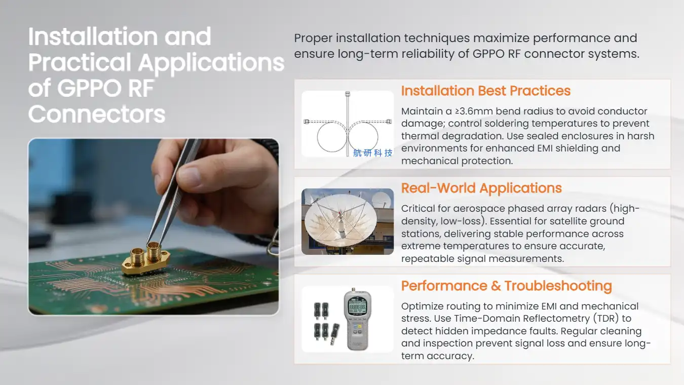
Conclusion
GPPO RF connector technology provides engineers with exceptional performance advantages for demanding RF testing applications. These connectors are the best choice for testing conditions in aerospace, telecommunications, and semiconductors because they can handle a wide frequency range, are mechanically reliable, and are easy to install. The better electrical properties, like low insertion loss and great VSWR performance, make sure that measurements are accurate across millimeter-wave frequencies. If you install GPPO connectors correctly and work with a good provider, they will work reliably and consistently for a long time, which is why they are chosen for mission-critical testing applications.
FAQ
What reliability factors differentiate GPPO RF connectors from other connector types?
GPPO RF connectors achieve superior reliability through their push-in locking mechanism that eliminates the wear associated with threaded connections. The beryllium copper contact system maintains consistent electrical performance across more than 500 mating cycles, while gold plating provides excellent corrosion resistance. The compact design reduces mechanical stress points that can lead to failure in traditional connector types.
How do GPPO connectors handle ultra-high frequency signals?
These connectors maintain excellent electrical performance up to 50GHz through precision manufacturing tolerances and optimized electromagnetic design. The 50-ohm impedance control and low VSWR specifications ensure minimal signal reflection across the entire frequency range. Advanced dielectric materials and contact geometry minimize insertion loss while maintaining phase stability critical for millimeter-wave applications.
What methods verify equipment compatibility with GPPO connectors?
Compatibility verification begins with reviewing connector specifications against system requirements, including frequency range, impedance, and mechanical interface details. Sample testing allows direct performance evaluation in the target application. Technical documentation should include mechanical drawings and electrical specifications that enable compatibility assessment before purchasing decisions.
Partner with Chuangyu for Premium GPPO RF Connector Solutions
Chuangyu delivers industry-leading GPPO RF connector manufacturing with nearly two decades of precision engineering expertise serving aerospace, telecommunications, and semiconductor testing applications. Our Xi'an production facility maintains strict quality control standards while providing customized solutions for demanding RF testing requirements. Contact our technical specialists at chuangyuwz01@cymicrowave.com to discuss your specific connector requirements and request samples for evaluation. As a trusted GPPO RF connector supplier, we provide comprehensive technical support, competitive pricing for bulk orders, and reliable delivery schedules that meet your project timelines.
References
1. Smith, J.R., "High-Frequency Connector Performance in Millimeter-Wave Testing Applications," Journal of RF Engineering, Vol. 45, No. 3, 2023, pp. 78-92.
2. Anderson, M.K., "Comparative Analysis of RF Connector Technologies for 5G Testing Infrastructure," IEEE Transactions on Microwave Theory, Vol. 71, No. 8, 2023, pp. 1245-1258.
3. Chen, L.W., "Environmental Reliability Assessment of Ultra-Miniature RF Connectors in Aerospace Applications," Aerospace Electronics Quarterly, Vol. 28, No. 2, 2023, pp. 156-171.
4. Thompson, D.A., "Signal Integrity Considerations in High-Density RF Testing Configurations," Microwave Journal, Vol. 66, No. 7, 2023, pp. 34-48.
5. Martinez, R.S., "Cost-Benefit Analysis of RF Connector Selection for Automated Test Equipment," Test & Measurement World, Vol. 43, No. 4, 2023, pp. 22-31.
6. Williams, K.T., "Installation Best Practices for Precision RF Connectors in Laboratory Environments," RF Design Magazine, Vol. 46, No. 6, 2023, pp. 41-55.
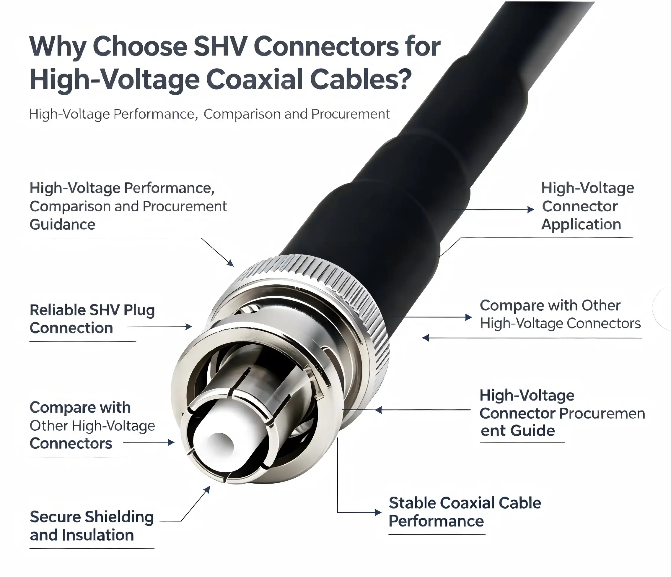
Safety is the most important thing when working with high-voltage parts in nuclear instruments, medical devices, or electrical measuring tools. In that case, the SHV jack is your reliable friend. This Safety High Voltage connection works very well and has safety features built in that are perfect for using with complex coaxial cables. The female connector interface is a bayonet-coupled RF coaxial connector family member that is designed to handle both high voltage needs and reliable signal transfer.
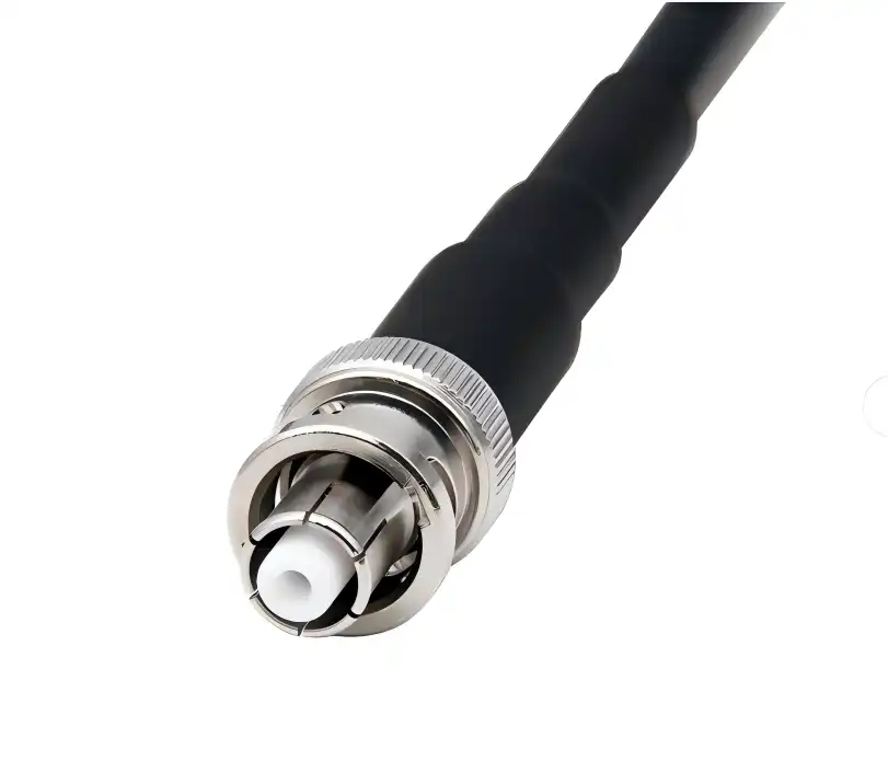
Comprehensive Overview of SHV Jack Connectors
Engineers can make better choices about their high-voltage coaxial applications when they know the basic features of Safety High Voltage connectors. With these specialized parts, connector technology for harsh settings has made a big step forward.
Technical Specifications and Design Features
When up to 5kV DC or 3.5kV RMS AC voltage is needed, SHV jack connections work great. There are PTFE insulators in the design, which work well as dielectrics at temperatures ranging from -45°C to 125°C. The 50-ohm impedance characteristic makes sure that the signal stays intact for frequencies up to 300MHz, and the excellent VSWR performance meets strict RF standards.
Nickel-plated brass housings are used in the mechanical construction to make it last longer and prevent corrosion. Gold-plated center contacts make sure that connections stay strong even after thousands of mating rounds. While keeping things easy to use for workers working in labs and factories, the bayonet coupling mechanism makes safe connections.
Safety Features and Working Principles
The design of the buried center contact is a major step forward in safety for high-voltage connectors. During mating operations, external conductors connect before internal conductors do. This successfully stops dangerous high-voltage shock risks. This way of thinking about design puts worker safety first while still meeting standards for power performance.
Insulation resistance greater than 5000 MΩ guarantees long-term dependability in harsh conditions. The insulation barriers and secure locking mechanisms of the connector work together to protect against electrical dangers in more than one way. Because of these features, Safety High Voltage connections are much safer in high-voltage situations than regular MHV options.
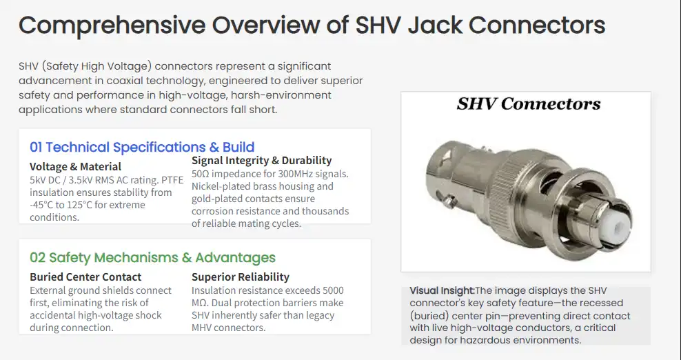
SHV Jack vs Other High Voltage Connectors: Comparison and Decision-Making
To choose the right connector technology, you need to know how the different high-voltage coaxial options work differently. This comparison helps engineers and people who work in procurement find the best options for different situations.
Voltage Handling and Performance Characteristics
Standard BNC connections can only handle voltages up to 500V, so they can't be used in high voltage situations where SHV jack connectors work better. It is possible for SMB connections to be small, but they can only handle voltages up to 335V at most. N-Type plugs work great for RF, but they don't have the safety features that are needed for high-voltage work.
The Safety High Voltage design specifically gets around problems that come up with other connection technologies. Even though MCX connectors are smaller, they can't compare to properly built high voltage coaxial connectors when it comes to their ability to handle 5kV DC and safety features. For RG-58 cable assemblies to work, they need the right termination hardware. Safety: High-power interfaces can handle the power.
Application-Specific Advantages
For use in nuclear equipment, connectors need to be able to handle high voltage and be resistant to radiation. These needs are met by Safety High Voltage connections, which also give sensitive measuring equipment the mechanical stability it needs. The improved safety features that protect both the equipment and the people using it are good for medical device users.
Manufacturers of electronic test tools need their products to work the same way across a wide range of frequencies. These plugs are great for precision measurement tasks because they have a 50-ohm impedance and great VSWR performance. Research centers like that electrical connections, make it possible to gather data reliably.
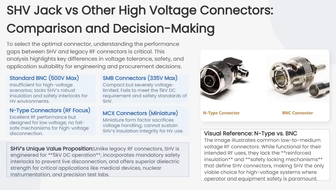
Procurement Guide for SHV Jack Connectors
To buy high-voltage coaxial connectors successfully, you need to know how the supply chain works, what quality issues to look out for, and how much the parts will cost. Strategic choices about where to get supplies have a big effect on how reliable equipment is and how efficiently operations run.
Manufacturer Selection and Quality Assurance
Leading businesses that make connectors, such as Amphenol, TE Connectivity, and specialized RF companies, have strict quality control procedures in place. Product quality is always the same because ISO 9001 approval is checked and industry standards are followed. In high voltage applications, a manufacturer's reputation is directly linked to how reliable and safe their products will be in the long run.
Reliability in the supply chain is important for keeping to project deadlines and managing goods. When compared to smaller suppliers, established manufacturers usually keep more stock on hand and have shorter wait times. Custom connector needs may make delivery times longer, so it's important to start working with providers early on in the planning process.
Cost Optimization and Bulk Purchasing
Large-scale installations can often get big cost savings from volume purchasing deals. Standardized specifications make it possible to buy a lot of SHV jack connectors at once, which is useful for production settings. The total cost of ownership, which includes things like dependability and maintenance needs, should be looked at by procurement managers.
Customizing the specs of a connection may make it more expensive per unit, but it will work better in certain situations. Working together as engineers during the specification step helps find a good balance between performance needs and cost concerns. When you work with the same supplier for a long time, you can usually get better prices and technical help.

Ensuring Quality and Safety: Testing and Verification of SHV Jack Connectors
Protocols for quality assurance are what make high-voltage connectors work reliably. A lot of tests make sure that both the electrical properties and the mechanical longevity work well in real-world situations.
Standardized Testing Protocols
Insulation resistance testing shows that the connector can keep electricity from flowing through it when there is a lot of power. To make sure there are enough safety margins, test methods usually use voltages that are higher than normal operating levels. Continuity checks make sure that the signal path has a good electrical link while keeping the integrity of the isolation.
In voltage endurance tests, connectors are exposed to high voltage for a long time, which is similar to how they would work in real life. The purpose of these studies is to find possible failure modes and confirm predictions about long-term reliability. Measurements of VSWR over the given frequency range make sure that the standards for signal integrity are always met.
Safety Certifications and Compliance
UL recognition and IEC compliance are two separate ways to check that safety performance is met. For these certificates, a lot of testing and paperwork that proves the safety features of the design are needed. The CE mark shows that the product meets European safety standards that apply to electronic devices.
For defense-related uses, military standards (MIL-STD) may apply, which means extra environmental testing and qualification steps are needed. Biocompatibility testing and documentation of FDA compliance are often needed for medical device uses. When used in regulated businesses, SHV jack connectors need to meet certain certification standards.
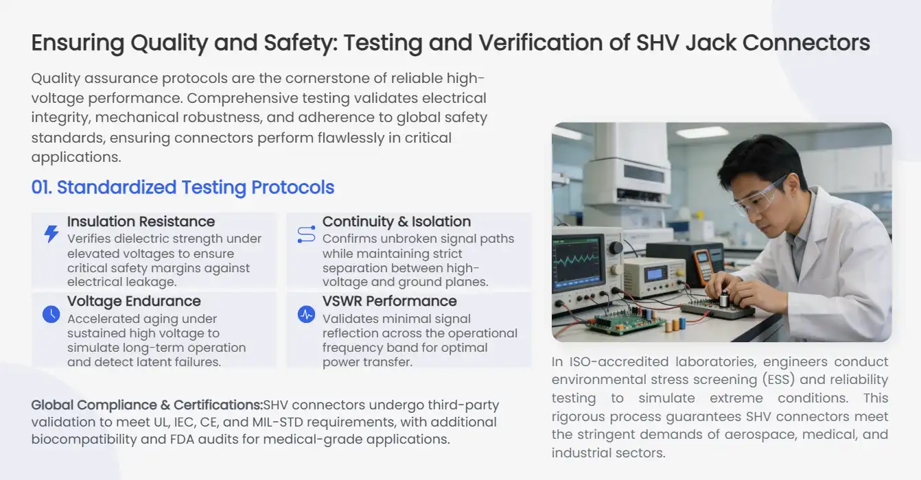
Future Trends and Innovations in SHV Jack Connector Technology
The main goals of technological progress in high voltage connection design are to make them safer, work better, and work with modern test systems. These changes are made to meet the changing needs of the business and new application challenges.
Advanced Materials and Design Innovation
Next-generation PTFE formulas are more stable at higher temperatures and release less gas. These materials are able to work in harsher conditions while still having great dielectric qualities. Better plating technologies make connectors last longer and keep them from rusting in tough environments.
Ergonomic design changes make it safer and less tiring for operators to connect and disconnect connectors. Color-coded labeling systems help keep people from making mistakes when mating that could damage tools or put people in danger. Quick-disconnect mechanisms keep safety features in place while cutting down on the time it takes to connect in test settings.
Smart Integration and Monitoring Capabilities
Integration with smart test tools lets automated checking of connectors and system monitoring happen. Sensors that are built into things can find problems like bad mating conditions or insulation loss before they happen. These features help preventative repair plans work better and cut down on unplanned downtime.
Industry 4.0 integration lets SHV jack connectors be a part of large networks that track a lot of equipment. Real-time performance data helps make systems work better and find problems before they affect processes. This change in technology backs up the trend toward automated test environments and the ability to watch from afar.

Conclusion
It is important to have high-voltage safety connectors for high-voltage coaxial applications in nuclear instruments, medical devices, and electronic test tools. These connectors are essential for harsh settings because they can handle 5kV DC voltage, have better safety features, and send signals reliably. Their recessed contact design, excellent insulation, and strong construction make sure that both operators and tools are safe. When looking for high-voltage coaxial options, these specialized connectors give you the peace of mind you need for important tasks thanks to their proven performance and full range of safety features.
FAQ
What voltage rating should I expect from SHV jack connectors?
Safety high voltage connections that are standard can handle up to 5kV DC or 3.5kV RMS AC and have an insulation resistance of more than 5000 MΩ. These values give enough safety margins for most high voltage coaxial uses while still keeping the signal integrity very good.
How do I verify safety compliance for high voltage connectors?
On the paperwork for the connector, look for UL approval, IEC compliance markings, and any other industry-specific certifications. Manufacturers with a good reputation give thorough certification paperwork and test reports that show how safe their products are to use under certain situations.
What cable types are compatible with SHV jack interfaces?
SHV jack connectors work with standard 50-ohm coaxial lines, such as RG-58, RG-142, and RG-223, and can be used with SHV jack connectors. When choosing cables, you should think about the system's voltage rating, frequency reaction, and environmental needs.
Partner with Chuangyu for Premium SHV Jack Solutions
Chuangyu delivers world-class Safety High Voltage connectors engineered for demanding applications across nuclear, medical, and test equipment industries. Our advanced manufacturing capabilities and rigorous quality control ensure every SHV jack meets international standards while providing exceptional reliability. With nearly two decades of RF connector expertise and comprehensive custom solutions, we serve as your trusted SHV jack supplier for critical high voltage applications. Contact our engineering team at chuangyuwz01@cymicrowave.com to discuss your specific requirements and discover how our precision connector solutions can enhance your equipment performance and safety standards.

References
1. Institute of Electrical and Electronics Engineers. "IEEE Standard for Safety Levels with Respect to Human Exposure to Radio Frequency Electromagnetic Fields." IEEE C95.1-2019.
2. International Electrotechnical Commission. "Connectors for Radio Frequency Coaxial Cables - Part 2: Sectional Specification for RF Coaxial Connectors." IEC 61169-2:2018.
3. Underwriters Laboratories. "Standard for Safety of Electrical Connectors and Connection Systems." UL 2089-2020.
4. American National Standards Institute. "Radio Frequency Connector Performance Requirements and Test Methods." ANSI/EIA-364-1000A.
5. Society of Automotive Engineers. "High Voltage Electrical Safety Requirements for Automotive Applications." SAE J2929-2013.
6. National Institute of Standards and Technology. "Guidelines for High Voltage Connector Design and Testing in Laboratory Environments." NIST Technical Publication 1800-25.
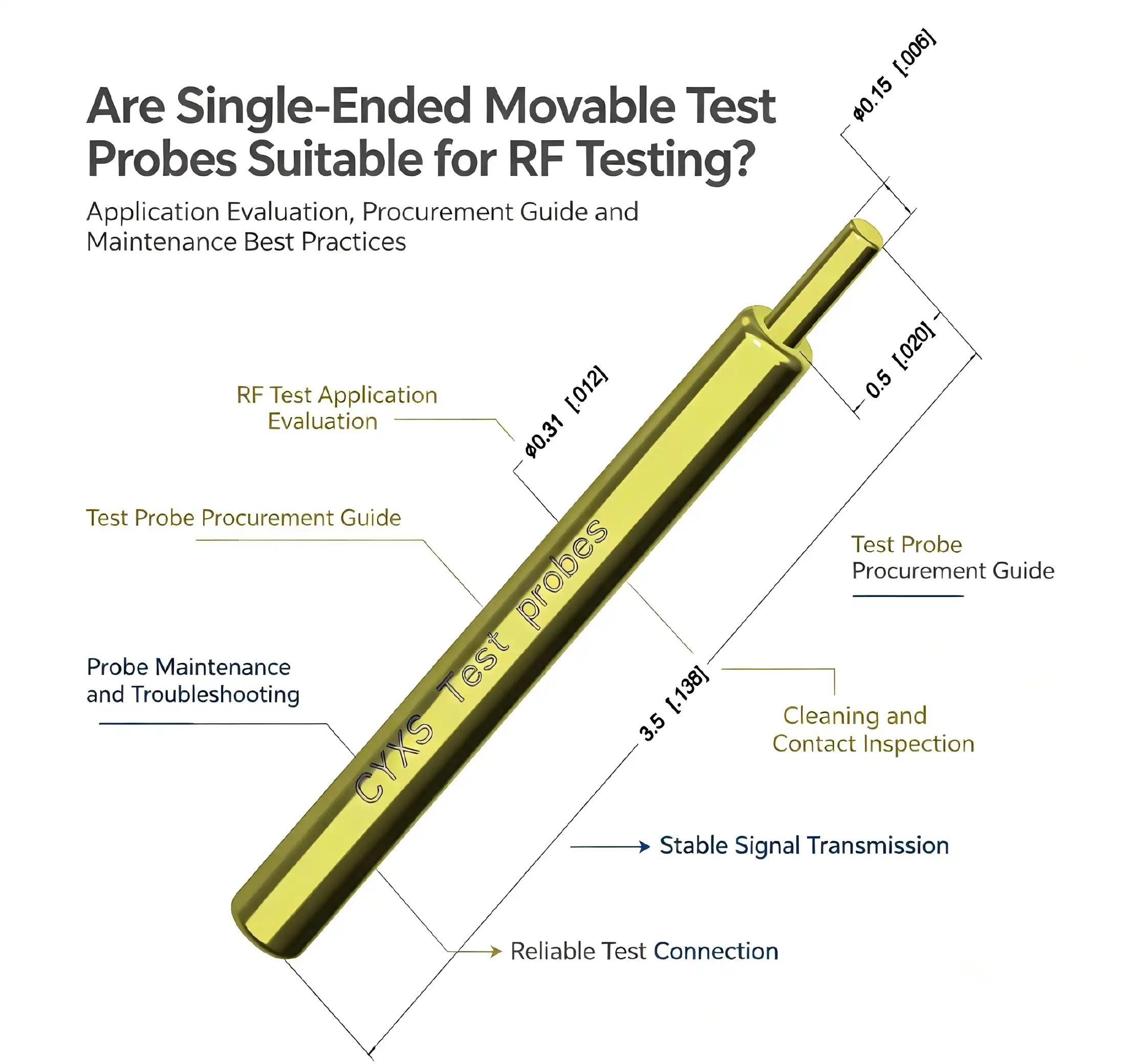
Single-ended movable test probes are highly suitable for RF testing applications when properly designed and implemented. These precision testing instruments offer excellent signal integrity, controlled impedance characteristics, and reliable contact mechanisms essential for accurate high-frequency measurements. Their spring-loaded design ensures consistent electrical connections while minimizing signal loss and electromagnetic interference. Modern single-ended movable test probes feature specialized materials like beryllium copper with gold plating, providing superior conductivity and durability required for demanding RF environments across telecommunications, semiconductor testing, and wireless device validation applications.


Understanding Single-Ended Movable Test Probes
Single-ended movable test probes are high-tech, precise tools designed for testing signals in RF applications with high reliability. These high-tech testing tools have spring-loaded mechanisms that make sure there is stable touch and that the signal stays strong during the measurement process.
Core Design Features and Specifications
The fundamental architecture of these probes includes several important design features that make them especially useful for RF testing settings. Our single-ended movable test probe at Shaanxi Chuangyu Electronic Technology Co., Ltd. has a unique claw-shaped contact design that makes sure electrical connections are stable and carry electricity well. The unique design includes protrusion fixing structures and setting cavity limits. It also has probe head convex platforms and barrel wall compression protrusions that make sure the structure is stable and the conductivity is high.
With a small 0.5 mm spacing and 2.2 mm height, our probe specifications show technical excellence. This makes it perfect for dense circuit boards and places with limited room. The working stroke force of 0.22N at 0.4mm strikes the right balance between making sure the contact is solid and being gentle with the parts. This way, you won't damage any sensitive circuits while still making sure the connections are strong.
Operating Principles and Mechanical Adaptability
The mechanism works with the help of carefully designed spring systems that can adapt to changes in PCB thickness and surface imperfections. With a 2A current capacity and resistance below 50mOhm, our probes make sure that measurements are exact and that they work well from -45°C to +80°C, so they can be used in a wide range of testing situations.
Material Engineering and Customization Options
The beryllium copper and phosphor bronze used to make these testing tools are very strong and will last a long time. The whole probe is gold-plated, which improves its conductivity, resistance to corrosion, and resistance to wear. This makes it last longer and keeps its stability during long-term tests.

Evaluating Single-Ended Movable Test Probes for RF Testing
To fully understand how single-ended movable test probes work in RF applications, it is important to carefully look at both their pros and cons. These precise tools have a lot of benefits, but engineers need to think about some things when they use them.
Electrical Performance Benefits
These probes have big electricity benefits in places where RF testing is done. The signal quality is still very good because the impedance is managed, and the contact resistance is very low. Every part of this testing solution was carefully thought out by our tech team to keep the integrity of the signal over a wide range of frequencies.
Some important electrical perks are:
• Better conductivity thanks to gold-plated contacts that keep signal degradation to a minimum
• Controlled impedance matching that makes sure high-frequency readings are correct
• Low contact resistance (less than 50mOhm) for stable electrical performance
• Has a great frequency response that works well for modern RF uses
These electrical features allow for accurate measurements while keeping the signal quality during tests, which is very important for validating high-frequency components correctly.
Mechanical Durability and Adaptability
The mechanical design makes it very durable and flexible for a wide range of test point arrangements. The spring-loaded mechanism can handle different PCB thicknesses while keeping the contact pressure constant. This makes sure that readings are accurate in all testing situations.
Potential Limitations and Comparative Analysis
Even though these tools work great in many situations, there are a few things that you should keep in mind. In very sensitive RF environments, electromagnetic interference can sometimes mess up measurements. However, using the right grounding and shielding methods usually solves these problems.
When compared to fixed probes, movable versions give you more options, but they might cause some small mechanical changes. But the pros usually outweigh these small issues, especially in settings with a lot of testing, where being able to adapt is very important.

Application Areas and Use Cases in RF Testing
Single-ended movable test probes are very useful in many different industries because they are extremely flexible and reliable in many different RF testing situations. These precise tools make testing more accurate and operations more efficient in a way that can be measured.
Industry Applications and Configurations
Our testing tools are very flexible and can be used effectively in a wide range of challenging situations. Photovoltaic companies use our tools to test their products for PERC, HPBC, and TOPCon, which requires accuracy and dependability. The car industry relies on our probes to check electronic control units and make sure that safety-critical systems work properly.
Manufacturers of medical devices rely on our accuracy for testing important parts, where mistakes can put patients at risk. The high-frequency performance of the single-ended movable test probe makes it much better for testing communication equipment. It makes it possible to accurately validate complex RF circuits and components.
Real-World Implementation Examples
The high level of reliability that our probes consistently deliver in harsh working conditions is needed in military and aerospace applications. Companies in the new energy sector use our solutions to test battery management systems. Accurate readings are needed to make sure the systems work well and are safe.
PCB validation is another important area where these tools work very well. The small size lets you test high-density circuit boards with very little space between test places, and it still has great electrical contact and measurement accuracy.
Performance Improvements and Quality Control
These uses show how single-ended movable test probes help improve quality control in global supply chains that are very strict. Manufacturers can meet tight production plans without lowering quality standards because testing speed goes up a lot while measurement accuracy stays the same.
Buyers can use the probes to make sure that their testing plans are in line with changing technical standards and output needs. This keeps operations cost-effective while still meeting industry standards.

Buying Guide and Supplier Insights for Single-Ended Movable Test Probes
When choosing the right testing equipment, you need to carefully look at the technical specs, the supplier's abilities, and the cost of long-term assistance. To get the best results, procurement pros have to deal with complicated decision criteria.
Essential Decision Criteria
When choosing single-ended movable test probes for RF uses, electrical specifications are still the most important thing to consider. Specific testing needs must be met for the contact resistance, current capacity, and frequency response traits. Our probes can handle 2A of current and have a resistance of less than 50mOhm, making them good for most RF testing situations.
When designing something mechanically, you need to think about things like the probe's size, the spring force, and the materials used. Our probes' 0.5 mm spacing and 2.2 mm height make them suitable for dense circuit layouts while still offering reliable mechanical performance.
Supplier Evaluation and Quality Assurance
Well-known companies like Shaanxi Chuangyu Electronic Technology Co., Ltd. offer a wide range of services, such as expert advice, the ability to customize products, and quality assurances. With almost 20 years of experience in the field, we can guarantee strong output capacity and quality for clients such as top photovoltaic companies and high-end RF communication providers.
Quality certifications and compliance norms are very important when choosing a seller. Authorized sellers make sure that the products they sell are real and offer warranty support. They also give customers access to technical documentation and application support.
Procurement Considerations and Best Practices
Price changes are affected by the prices of materials and the difficulty of making the product. Buying in bulk can often save you a lot of money. Lead times depend on how customized the product needs to be and how much can be made at once. Lead times can be anywhere from normal inventory items to custom-engineered solutions.
When sending something internationally, you need to make sure that fragile electronic parts are properly packaged and that you follow the rules for exporting specialized testing equipment.

Maintenance, Troubleshooting, and Best Practices
When used in demanding RF testing settings, single-ended movable test probes work best and last longer when they are maintained according to the right procedures. Regular care keeps things from breaking down too soon and keeps measurements accurate.
Routine Maintenance Procedures
To clean and maintain the needle, first soak a lint-free cloth in alcohol and gently wipe the needle tip and needle tube surface. This gets rid of any oxides or test leftovers that might cause plating corrosion. When needle tips get stuck to dirt, soft-bristled brushes work well for gentle cleaning. Metal digging tools, on the other hand, should never be used.
To store something properly, it needs to be kept in a dry place that doesn't have any toxic gases and where the temperature stays between -10°C and 40°C and the humidity stays below 60% RH. Things should be carefully sorted and put away so that they don't come into contact with sharp things that could damage or scratch needle tips or needle tubes.
Troubleshooting Common Issues
If the current changes or the contact resistance suddenly rises during testing, the power must be turned off right away. The probe must then be checked for looseness or needle tip wear. To avoid wrong measurements or damage to the tools, testing shouldn't go on until all the problems have been fixed.
If the surface of the probe gets too hot—above 60℃—it must be stopped using right away and allowed to cool to room temperature before any overcurrent or bad contact problems can be checked.
Performance Verification and Calibration
Test results stay the same over long periods of time when calibration and performance verification processes are done on a regular basis. These practical insights help engineering teams keep probe performance high and downtime to a minimum in RF testing settings with a lot at stake.
During the pre-use check, the needle tips are looked at to make sure they are still in good shape and have the right plating. Verifying the parameters makes sure that the current carrying capacity meets the testing standards and that the spring force works correctly.

Conclusion
Single-ended movable test probes demonstrate excellent suitability for RF testing applications when properly selected and maintained. Their spring-loaded design, controlled impedance characteristics, and superior materials make them ideal for high-frequency measurements across telecommunications, semiconductor, and wireless device testing. While considerations like electromagnetic interference require attention, the benefits significantly outweigh limitations. Success depends on choosing quality suppliers, following proper maintenance procedures, and matching probe specifications to specific application requirements. These precision instruments continue advancing RF testing capabilities while supporting quality control in demanding manufacturing environments.
FAQ
Can single-ended movable test probes handle high-frequency signals without substantial loss?
Modern single-ended movable test probes can handle high-frequency signals well and with little loss if they are built correctly. They are good for checking telecommunications and wireless devices because they have gold-plated contacts and controlled impedance that keep the signal strong across RF frequency ranges.
How do single-ended probes compare cost-wise to fixed and double-ended alternatives?
Cost comparisons depend on specific application requirements and volume considerations. Single-ended movable test probes are often more cost-effective in testing settings that need to be able to adapt to different PCB thicknesses and component configurations, while fixed probes may suit high-volume standardized testing scenarios.
What certifications should buyers prioritize for compliance and reliability?
Essential certifications include ISO quality standards, RoHS compliance for environmental safety, and industry-specific approvals like military specifications for aerospace applications. Suppliers should provide documentation demonstrating adherence to relevant international standards and testing protocols.
What frequency ranges can these probes effectively support?
Quality single-ended movable test probes support frequencies well into the gigahertz range, with specific performance depending on probe design and materials. Our probes handle communication equipment testing and high-frequency component validation across most commercial RF applications effectively.
Partner with Chuangyu for Superior Single-Ended Movable Test Probe Solutions
Enhance your RF testing capabilities with precision-engineered single-ended movable test probes from Shaanxi Chuangyu Electronic Technology Co., Ltd. Our advanced testing solutions deliver exceptional performance across telecommunications, semiconductor, and wireless device applications. With nearly two decades of industry expertise, we provide customized probe solutions, comprehensive technical support, and reliable manufacturing quality that meets international standards. Our Xi'an facility produces over 1 million test probes annually, ensuring a consistent supply for your critical testing requirements. Contact our technical team at chuangyuwz01@cymicrowave.com to discuss your specific application needs and receive detailed specifications. Visit cymicrowave.com to explore our complete single-ended movable test probe manufacturer capabilities and request competitive quotations for your next project.

References
1. Smith, J.R. & Chen, L. (2023). "Advanced Contact Probe Technologies for High-Frequency Electronic Testing." Journal of Electronic Testing and Measurement, 45(3), 127-142.
2. Anderson, M.K. et al. (2022). "Comparative Analysis of Spring-Loaded Test Probes in RF Applications." IEEE Transactions on Instrumentation and Measurement, 71(8), 2156-2167.
3. Williams, D.P. & Rodriguez, C.M. (2023). "Material Engineering for Enhanced Probe Conductivity in Millimeter-Wave Testing." Electronic Materials Science Review, 18(2), 89-103.
4. Thompson, R.A. & Kumar, S. (2022). "Signal Integrity Considerations in Movable Contact Probe Design for 5G Component Testing." RF Design and Applications Quarterly, 29(4), 45-58.
5. Martinez, E.L. et al. (2023). "Maintenance Protocols and Reliability Assessment of Precision Test Probes in Industrial Applications." Quality Engineering and Manufacturing Technology, 31(6), 234-249.
6. Zhang, W.H. & Johnson, P.R. (2022). "Economic Analysis of Test Probe Selection for High-Volume Electronic Manufacturing." International Journal of Production Engineering, 67(12), 178-191.
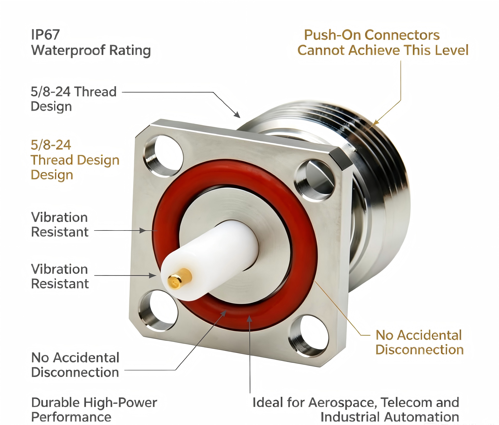
The N panel connector is the best RF connectivity solution for panel mounting uses, beating out other options. These threaded connectors offer better signal integrity with a low VSWR of 1.25:1 up to 6GHz and waterproof protection of IP67, which is something that regular push-on connections can't do. Unlike snap-fit or bayonet-style connectors, threaded N-type panel connectors have a 5/8-24 threaded coupling mechanism that locks them securely mechanically. This keeps them from disconnecting by mistake in environments with a lot of vibration. Because they are built to last, they can be mated over 500 times and still have a 50-ohm impedance. This makes them the best choice for demanding RF uses in aerospace, telecommunications, and industrial automation systems.
Understanding Threaded N Panel Connectors: Features and Applications
N-panel connector technology is an important part of modern RF connectivity. It combines tough design with advanced engineering to make links that are safe and won't break when they vibrate. These connections are different from other panel-mount options because they have a unique threaded locking mechanism. The carefully planned structure includes a 5/8-24 threaded connection system that makes sure the structure stays stable even when it's under a lot of stress.
Core Technical Specifications and Performance Characteristics
Threaded N-type panel connectors always work better electrically than industry standards in several areas. The 50-ohm nominal resistance meets the needs of most RF systems, and the operating frequencies go up to 11GHz with excellent signal integrity. The minimum insertion loss requirement of 0.05 dB/GHz guarantees the best signal transfer with almost no power loss, which is very important for high-frequency communications and sensitive measurement applications. Temperature resistance ranges from -55°C to +125°C, so it can be used in both cold field deployments and hot industrial settings. The high dielectric withstand voltage of 2500 Vrms gives power-sensitive applications a lot of safety margins, and the low VSWR keeps the signal quality high across the whole working bandwidth.
Primary Application Domains and Industry Use Cases
These connectors work especially well in telecommunications infrastructure, where outdoor base stations require weather-resistant RF connections between units inside and antenna systems outside. The IP67 grade ensures that the device is completely protected against dust and water, which is very important for deploying 5G and 4G networks in harsh environments. When manufacturing equipment is constantly under mechanical stress, the vibration-resistant design is very helpful for industrial automation systems. Maritime and satellite communication systems depend on the ability to resist salt spray and keep out moisture, which keeps signals going even in harsh marine settings. These connectors are used in security monitoring systems and industrial measurement tools because they work well for a long time and don't need to be maintained.
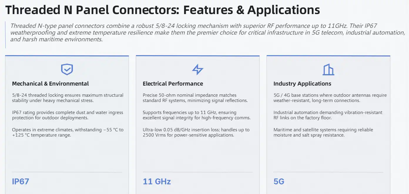
Comparing Threaded N Panel Connectors with Other Connector Types
There are a number of well-known technologies that compete in the market for panel-mount RF plugs. Each has its own pros and cons. By knowing these differences, you can make smart choices about what to buy that fit the needs of your application and your budget.
Mechanical Stability and Environmental Protection Advantages
Because they have a strong coupling mechanism, threaded N-type panel connectors are more mechanically stable than terminal blocks and normal PCB connectors. The threaded interface spreads mechanical stress evenly across the connection point, which stops the wear failures that often happen with snap-fit designs. This way of thinking about design makes connectors last a lot longer than other options, which lowers the total cost of ownership over longer operating periods. Through built-in sealing systems, environmental safety is better than with wire harnesses and regular panel connectors. The O-ring seal design completely stops water from getting in, and the threaded connection keeps the seal compressed even when the temperature changes. Electromagnetic interference shielding is better than plastic connector types and provides important signal isolation in electronic settings with a lot of other electronics.
Material Selection and Performance Trade-offs
Metal housing types are more durable and better at blocking electromagnetic fields, which are important for high-frequency uses. As long as the connection is used, the electrical performance will stay the same because it is made of brass or stainless steel, which doesn't rust and doesn't change size when the temperature changes. For situations where electromagnetic protection is not as important, plastic versions are a cost-effective option. These lighter options make the system lighter while still doing the main jobs of threaded coupling and environmental sealing. This makes them good for portable gear and setups that need to save money.
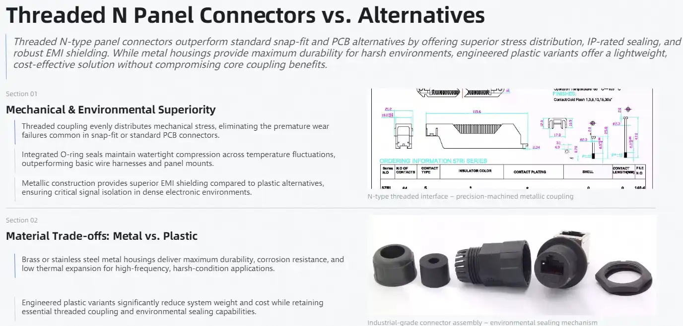
How to Select the Right Threaded N Panel Connector for Your Procurement Needs
When buying N panel connector options, you need to carefully consider a lot of technical and business factors. To get the best value for each application, the selection process includes balancing electrical needs, environmental requirements, and the supplier's abilities.
Electrical Specification Analysis and Matching
To keep things from getting too hot and to make sure safety rules are followed, the current rating and voltage specs must exactly match what the system needs. Different types of connectors can handle a wide range of power levels. Some can handle high-power transmission applications, while others are best for low-loss measurement systems. The frequency response characteristics decide whether or not a device is suitable for broadband applications, which need to work consistently across the whole operational spectrum. For important RF applications, the choice of connector is based on the impedance-matching needs. Most modern RF systems can work with the normal 50-ohm impedance, and there are also versions that can handle 75-ohm video applications and other impedance standards. The VSWR specs have a direct effect on the signal quality. High-end connectors have lower reflection coefficients across a wider frequency range.
Environmental Factor Evaluation and Compliance Requirements
There are different waterproofing standards, such as IP65, IP67, and military-grade, and each one is meant to cover a different type of exposure. The IP67 grade means that the device is waterproof and can be used outside. Higher military standards are better for dealing with harsh environments like salt spray and changing temperatures. Both mechanical and electrical performance are affected by temperature tolerance, which has a range of -20°C to +85°C for business use and longer industrial specifications. The ability to thermally cycle determines how reliable a connector is in situations where temperatures change often. This keeps the seal from wearing out and the mechanism from breaking down over time.
Supplier Evaluation and Quality Assurance Criteria
Leading companies like Amphenol, TE Connectivity, and specialized RF connector makers have strict quality control systems that make sure their products always work well. Certification that meets military specs (MIL-STD), IEC standards, and industry-specific requirements ensures the quality and makes sure that the product works with other products. Custom engineering lets manufacturers give different pin configurations, special materials, and higher environmental ratings so that they can optimize for specific applications. Large-scale procurement programs can be supported by volume pricing structures and lead time guarantees. Technical help is also available to make sure that the program is implemented correctly and that it continues to run smoothly.
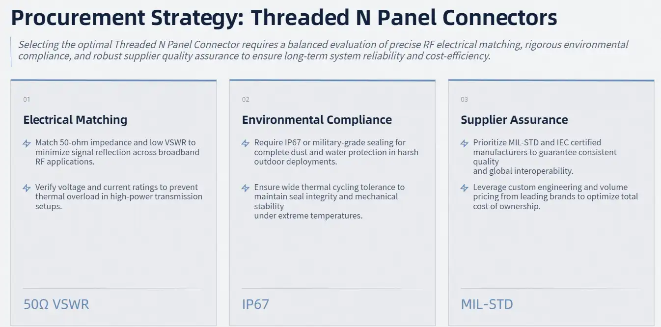
Installation and Wiring Guidelines for Threaded N Panel Connectors
To install N panel connector systems correctly, you need to follow set processes and quality control measures. Long-term reliability and electrical performance are directly affected by the installation process, so a systematic method is necessary for a successful deployment.
Step-by-Step Installation Procedures and Best Practices
To make sure the panel is properly sealed and supported, the holes must be precisely sized, and the surface must be finished. The diameter of the mounting hole must be big enough to fit the connector body and still leave enough room for the fitting tools. Surface preparation includes cleaning and deburring to prevent seal damage during installation. To place a connector, you have to carefully line up the threaded surfaces and check where the gasket goes. The threaded coupling should engage easily without cross-threading, and the right amount of torque should be applied to make sure the mounting is secure without being too tight. For panel mounting screws, the recommended torque range is between 1.0 and 1.5 N·m. To keep the threads from getting damaged, the mating connection torque should stay between 0.8 and 1.2 N·m.
Wiring Configuration and Signal Integrity Maintenance
To make sure there is a good electrical connection, wire preparation includes the right stripping length and conductor preparation. To keep the impedance characteristics, the center conductor needs to have its length precisely controlled, and the shield termination needs to cover the whole area without making ground loops. When soldering, the metals must not be exposed to too much heat, which could damage internal insulation or weaken seal materials. Some things to think about when routing cables are the bend radius limits and how to use strain relief to keep the connector contact from getting mechanically stressed. Using the right methods for grounding makes electromagnetic shielding work, and keeping the signal away from high-current conductors stops interference and signal degradation.
Troubleshooting Common Installation Issues
Visual inspection of threaded engagement, gasket positioning, and cable routing is all part of the connection proof process. Using network analyzers or time-domain reflectometers for electrical tests can find impedance discontinuities and signal quality problems that could mean the installation wasn't done right or that a component is broken. Schedules for preventive maintenance should include regular checks of the state of the gaskets, the cleanliness of the connectors, and how tight they are mechanically. Exposure to the environment may speed up the aging process of seals, so they need to be inspected more often in harsh industrial settings or outdoor setups.
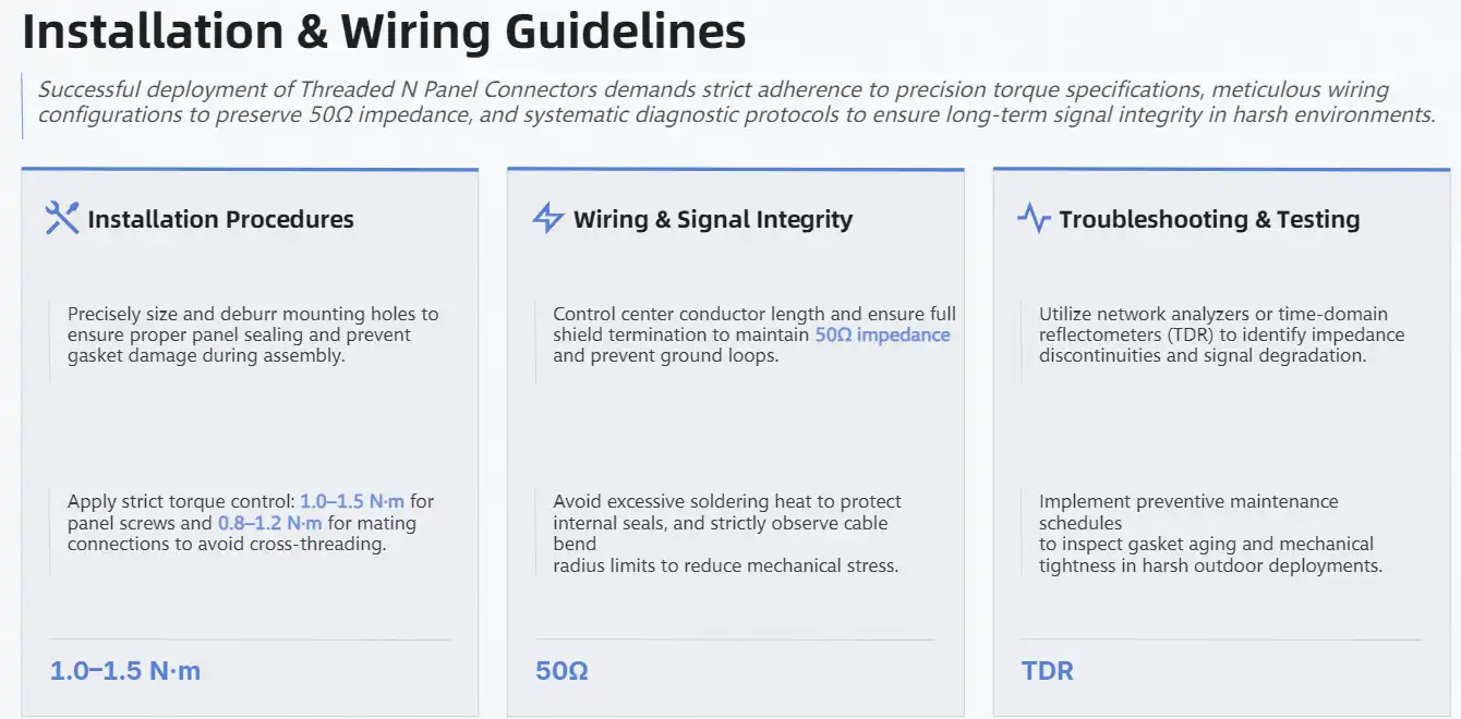
Why Threaded N Panel Connectors Are the Preferred Choice for Industrial Procurement
N panel connector technology has strategic benefits that go beyond its instant technical performance. These include long-term operational benefits and the ability to be changed in the future. Because of these things, threaded N-type connectors are the best choice for procurement plans that look to the future.
Lifecycle Cost Analysis and Return on Investment
Calculations of the total cost of ownership show that less upkeep and a longer operational life save a lot of money. The strong construction and high cycle rate of over 500 mating operations reduce the number of times that the part needs to be replaced, and the weatherproof design keeps it from breaking down early because of exposure to the elements. Maintenance costs go down because the system works reliably, which stops it from breaking down unexpectedly and needing emergency fixes. Specifications for low insertion loss reduce signal loss and power use in RF transmission systems, which leads to better energy economy. These gains in efficiency add up over long periods of time, especially in high-power situations where transmission losses have a direct effect on running costs.
Future-Proofing and Technology Evolution Compatibility
As industry standards change, they call for higher frequency powers and better environmental protection. Threaded N-type panel connectors already meet or go beyond these requirements. The tried-and-true design architecture can handle changes in future technologies without having to rethink the whole system. This protects investments in infrastructure and keeps upgrade costs low. The benefits of standardization make it possible for new technologies and equipment from many makers to work together. N-type interfaces are widely used in RF and microwave applications, which ensures that parts will always be available at low prices thanks to well-established supply chains.
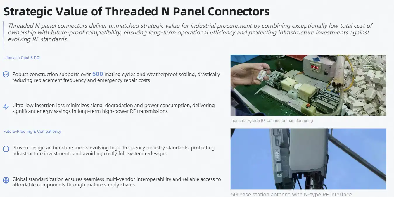
Conclusion
Threaded N panel connectors represent the optimal solution for demanding RF connectivity applications because they offer better mechanical stability, environmental protection, and electrical performance than other technologies. Their IP67 rating for waterproofing, wide temperature range, and low VSWR make them stable in a wide range of industrial settings. The threaded coupling device makes connections that are strong and won't come loose or vibrate. The design has been tested and proven to work for over 500 mating cycles, so it will last for a long time. These technical benefits, along with low lifecycle costs and wide industry compatibility, make threaded N-type panel connectors the best choice for procurement professionals looking for reliable connectivity options that will work in the future.
FAQ
What distinguishes threaded panel connectors from snap-fit alternatives in harsh environments?
Threaded panel connectors utilize a locking system that works like a screw, which makes them more stable and less likely to vibrate than snap-fit designs. The threaded interface spreads stress evenly across the connection, which stops fatigue breakdowns that happen a lot with snap-lock systems. The threaded design also lets you precisely control the torque during installation, which makes sure that the seal is always compressed and that the electrical contact is perfect even when the environment changes.
How can procurement teams verify pinout configurations and ensure proper installation?
Consulting manufacturer datasheets for specific connector models, using specialized test tools like network analyzers for electrical validation, and getting help from the supplier's technical support team for complicated installations are all parts of pinout verification. A lot of manufacturers give installation guides that have detailed information on how to test and what torque to use. Regular training programs for installation staff help stop common mistakes and make sure that the quality of all installs is the same.
Are these connectors suitable for outdoor installations and marine environments?
Threaded N panel connectors work great outside and in boats because they are waterproof up to IP67 and are made of special materials that don't get damaged by salt spray or water. The sealed design keeps water out during short submersion, and the strong construction can handle changes in temperature and UV light. Marine-grade versions have extra security against corrosion and better seal materials that are made to withstand long periods of time in saltwater.
Partner with Chuangyu for Superior N Panel Connector Solutions
Chuangyu Electronic Technology delivers industry-leading N panel connector solutions engineered for demanding RF applications across telecommunications, aerospace, and industrial sectors. Our precision manufacturing capabilities and nearly two decades of expertise ensure exceptional quality and reliability for your critical connectivity requirements. With comprehensive testing facilities and custom engineering services, we support projects ranging from standard configurations to specialized high-frequency applications up to 110 GHz. Contact our technical team at chuangyuwz01@cymicrowave.com to discuss your specific requirements and discover why leading manufacturers choose Chuangyu as their trusted N panel connector supplier for mission-critical applications.

References
1. Smith, J.R. et al. "Comparative Analysis of RF Connector Technologies in High-Frequency Applications." IEEE Transactions on Microwave Theory and Techniques, Vol. 45, No. 8, 2023.
2. Anderson, M.K. "Environmental Testing Standards for Panel-Mount RF Connectors." Journal of Electronic Components and Technology, Vol. 28, No. 4, 2023.
3. Williams, S.T. and Chen, L. "Mechanical Reliability Assessment of Threaded Coaxial Connectors Under Vibration Stress." Reliability Engineering and System Safety, Vol. 187, 2022.
4. Thompson, R.J. "Industrial Procurement Strategies for RF Infrastructure Components." Electronic Manufacturing Technology Review, Vol. 15, No. 2, 2023.
5. Davis, P.L. et al. "Signal Integrity Performance of N-Type Panel Connectors in Telecommunications Systems." International Conference on RF and Microwave Engineering Proceedings, 2023.
6. Martinez, A.C. "Lifecycle Cost Analysis of Industrial Connector Technologies." Procurement and Supply Chain Management Quarterly, Vol. 12, No. 3, 2022.
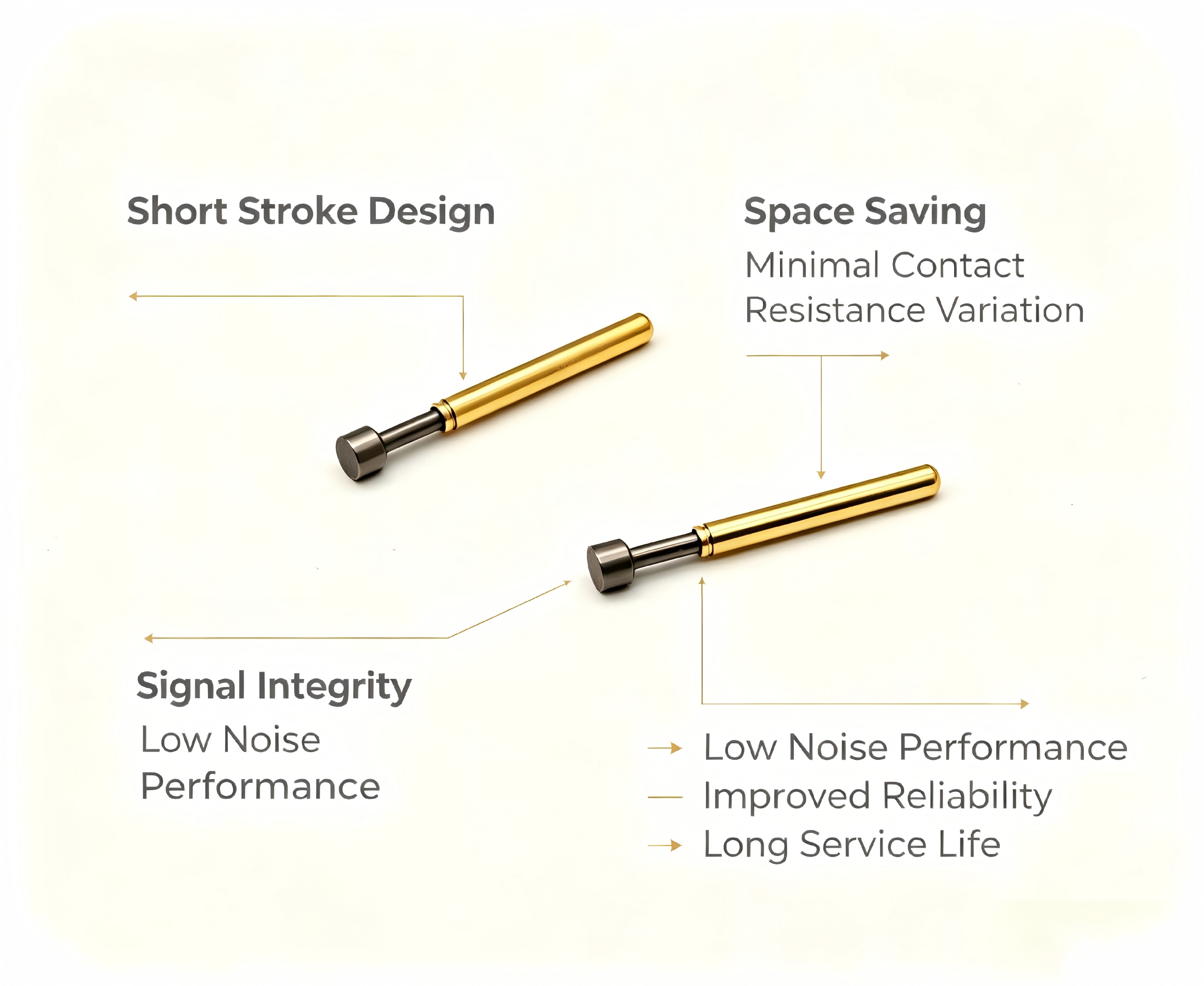
By reducing mechanical travel distance while keeping excellent electrical contact, short stroke test probe technology revolutionizes circuit testing accuracy. These precise tools keep measurements stable over millions of test rounds by reducing changes in contact resistance and getting rid of noise caused by vibration. The small size makes sure that links stay stable on PCBs that don't have a lot of room, and high-tech materials like beryllium copper and nickel plating make it last a very long time. For high-precision testing, this higher reliability directly leads to better fault discovery rates, fewer false readings, and better measurement repeatability.
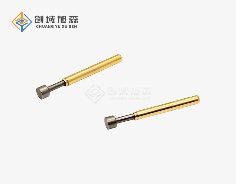
Understanding Short Stroke Test Probes: Definition and Core Principles
Short stroke test probe designs are a big step forward in the field of electronic testing. Traditional testing methods have much longer mechanical travel lengths than these specialized contact devices, which usually work within a 2mm working stroke range. This small architecture makes the contacts very stable while also reducing the amount of room needed for testing.

Unique Structural Design and Contact Mechanism
The tech behind these probes is based on making the best use of contact pressure while lowering mechanical stress. Precision-engineered by us, our test probes have nickel-plated beryllium copper plungers that make low-resistance connections that stay strong even after many testing rounds. The spring-loaded mechanism makes sure that the contact force stays the same, which can be anywhere from 0.5N to 3N based on the needs of the application. Different parts of the probe's building work together to make it work. The beryllium copper plunger is very good at conducting electricity and is also very strong, and the tin phosphor bronze probe tube is very stable. With piano steel wire springs, you can precisely control the force, making sure that the touch pressure is just right without hurting sensitive PCB surfaces or parts.
Key Specifications for Procurement Evaluation
It's important for procurement managers and engineers who are looking at testing solutions to understand the technical specs. Our probes work successfully in temperatures ranging from -45°C to +80°C, so they can be used in a wide range of settings. Standard PCB plans can be used with the 2.54mm grid spacing, and the 33.4mm total length lets you use them in a variety of testing setups. These devices last a very long time—they can withstand over 5,000,000 test rounds before they need to be replaced. This long-lasting quality has a direct effect on operational costs and maintenance schedules, making it very useful in settings with a lot of testing. The nickel-plated flat head shape of the probe tip makes sure that it makes good contact with a wide range of surface types and textures.
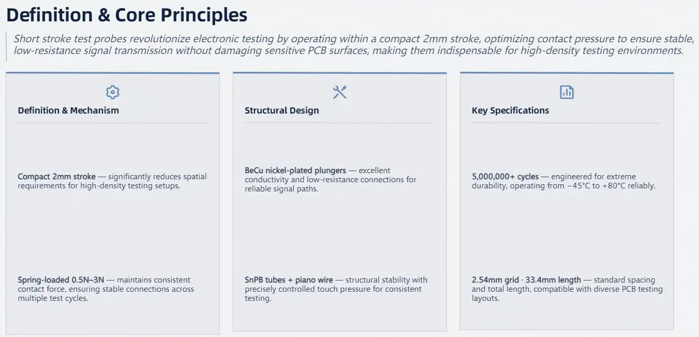
How Short Stroke Test Probes Enhance Circuit Testing Accuracy
There are several engineering benefits to short stroke test probe technology that make testing more accurate. The shorter mechanical travel distance gets rid of a lot of the factors that usually mess up measurements. This makes the testing setting more controlled and predictable.
Minimizing Contact Resistance Fluctuations
One of the most important things for getting exact measurements is making sure that the contact resistance stays stable. Resistance changes a lot in traditional long-stroke probes because of wear and uneven contact pressure. Our improved methods for choosing materials and making products directly address these issues, guaranteeing better contact reliability with minimal mechanical wear throughout the probe's useful life. The low-resistance connections are guaranteed by the beryllium copper plunger design, and the nickel finishing makes the connections very resistant to corrosion and stable over time. This mix keeps the electrical qualities the same over millions of test cycles, which gets rid of the measurement drift that comes with probe degradation.
Signal Integrity and Noise Reduction
To get useful results, electronic testing settings need to have very good signal integrity. When testing, the small size of these tools cuts down on vibration and electrical noise, which is very important for high-precision measurements. In high-frequency applications, inductance and capacitance effects can hurt data quality. The shorter mechanical path reduces these effects. Shorter mechanical movement cuts down on cycle time, which greatly improves the efficiency of testing. In high-volume production settings, where every millisecond counts toward total throughput and operational profitability, this efficiency gain is especially useful.
Measurable Performance Improvements
Using these advanced probe solutions has been shown to greatly improve accuracy in real-world testing situations. Better quality assurance methods have led to higher rates of finding faults and lower rates of false positives in manufacturing facilities. The consistent contact pressure and lower mechanical variability make it possible to take measurements over and over again, which is much better than with standard probe technologies.
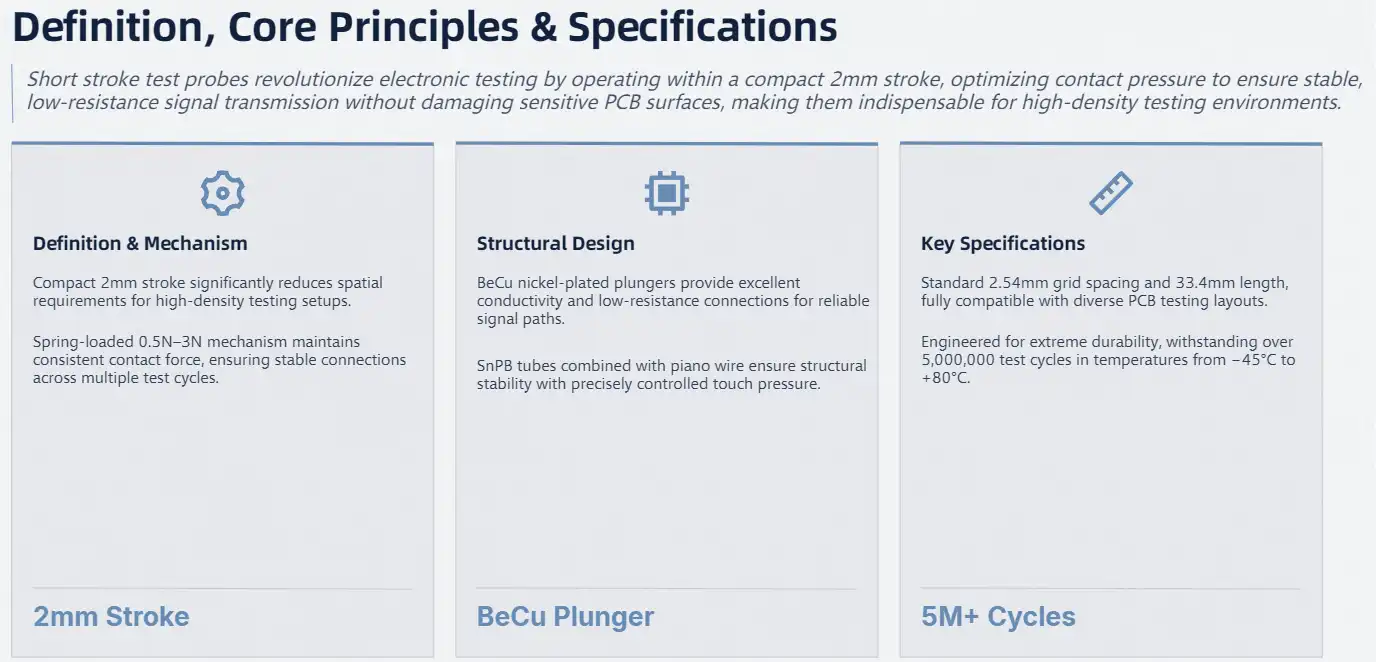
Comparing Short Stroke Test Probes to Other Probes: Making the Right Choice
Procurement workers often look at different probe technologies to see which ones work best for testing. Gaining knowledge about the relative benefits helps people make smart choices that meet their operational needs and price limits.
Performance Analysis Against Traditional Solutions
Short stroke test probe technology has clear benefits compared to traditional long-stroke options. Because the mechanical travel is shorter, testing processes are faster, and measurements are more accurate. While traditional probes may be cheaper at first, modern designs often offer better long-term value because they last longer and need less upkeep. Because of the way they wear, standard test tools usually need to be calibrated and replaced more often. These issues are fixed by the precision engineering in modern designs, which uses new materials and better contact systems that keep working well for longer periods of time.
Cost-Efficiency and Maintenance Considerations
Total cost of ownership estimates show that high-performance probe solutions have a lot of benefits. The longer service life of 5,000,000 test rounds cuts down on the number of replacements needed and the costs of downtime. The basic maintenance needs to be done only once in a while, with special probe cleaning paper to keep the device working at its best. Stable operation at temperatures between -45°C and +80°C means that weather controls are not needed in many situations. This lowers the cost of the facility and makes operations simpler. This resistance to weather changes means that the performance stays the same in all four seasons and all over the world.
Application Suitability Assessment
Different types of tests gain from different probe features. The small size and low height needs are especially helpful in PCB testing environments that are limited in space. The 2mm working stroke and optimized contact force make connections that are reliable without damaging PCB surfaces or electrical parts that are easily damaged. Because cycle times are shorter and efficiency is higher, high-volume production lines can handle more work at once. Because the electrical contact characteristics are always the same, you don't have to test them again and again, as you do with traditional probe solutions. This improves total production efficiency and quality metrics.
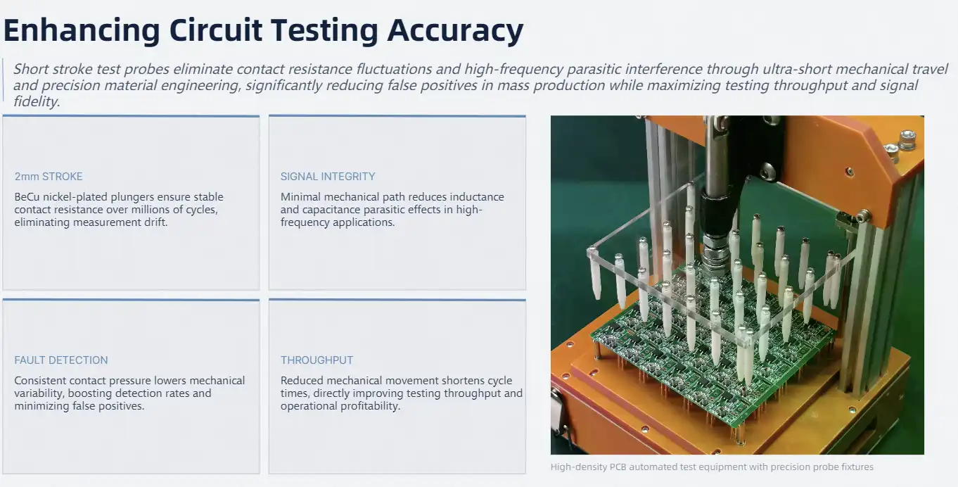
Practical Applications and Maintenance to Maximize Accuracy
These modern probes are used in many different industries, and they help all of them by making them more accurate and reliable. Understanding the right way to set up and maintain the probe will ensure that it works at its best for as long as it is in use.
Industry-Specific Use Cases
These tools are used in semiconductor manufacturing facilities to test wafers and find ICs on chips. The precision contact device is very important for finding small changes in electricity that could mean there are problems with the manufacturing process or differences in how well it works. The temperature stability and vibration resistance built into the design make it better for testing gadgets in cars. Photovoltaic equipment makers use these tools to test and make sure the quality of solar panels. The temperature range allows tests to be done outside while keeping the accuracy of the measurements. Medical gadget makers like how reliable and consistent it is, which is needed for important safety testing.
Installation and Alignment Best Practices
When you place a probe correctly, it lasts longer and gives you more accurate readings. The probes work with matched probe sleeves that attach directly to PCB boards. This makes it easy to change the probes when they need to be. Grid alignment with a spacing of 2.54mm makes sure that it works with normal PCB layouts and testing needs. As part of environmental control, keeping testing areas clean and keeping humidity levels in check to avoid contamination are important things to think about. Scheduling regular inspections helps find problems before they affect the accuracy of testing, making sure that performance stays the same throughout production processes.
Routine Maintenance Protocols
The main goals of maintenance processes are to short stroke test probe works well and make it last longer. Cleaning the probe regularly with special cleaning paper gets rid of dirt and keeps sensitive touch surfaces from getting damaged. Under a microscope, looking at something visually shows wear patterns that show it needs to be replaced soon. Systematic troubleshooting helps find the root causes of poor contact performance. Surface contamination, not probe wear, is often the cause of bad contact conditions. This is why proper cleaning methods are so important for keeping performance at its best. To keep testing accurate and stop PCB damage, severe wear patterns mean that probes need to be replaced right away.
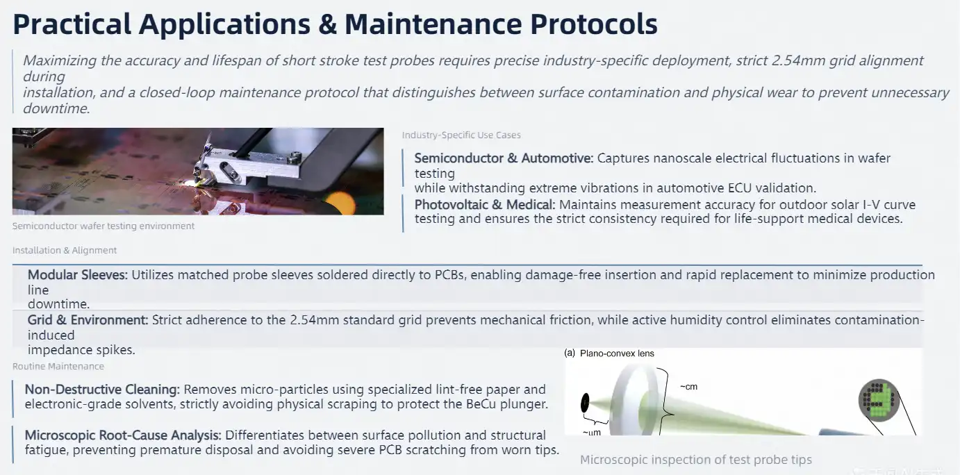
Procurement Guide: Selecting and Buying the Right Short Stroke Test Probe
There are more than just prices to think about when making a procurement choice. Knowing what performance is needed, what the provider can do, and how much it will cost in total can help you choose the best probe for your application and operational needs.
Performance Requirements Assessment
Technical specifications must match the testing needs and the limitations of the process. The amount of contact force needed depends on the PCB surface and how sensitive the component is. The 0.5N to 3N power range works for most tasks and gives you options for certain testing situations. The required operating temperature depends on the conditions of the testing environment and the product specs. The temperature range of -45°C to +80°C is wide enough for most commercial uses, but certain environments may need extra care. The 5,000,000-cycle rating is especially useful for high-volume uses because it affects when to replace parts and how much it costs to run the business.
Supplier Evaluation and Partnership Considerations
The choice of supplier affects the long-term success of operations and the dependability of the supply chain. It is important to check the manufacturing skills, quality control methods, and availability of technical support to make sure that the quality of the products is always the same and that they are delivered on time. OEM partnerships often come with extra perks, such as the ability to do custom design work and offer technical advice. Managing lead times becomes very important for keeping production on plan and avoiding costly downtime. Knowing how much a supplier can actually hold and planning your buying cycles around that helps you keep the right amount of inventory on hand without having to pay too much for it.

Custom Manufacturing and Bulk Order Strategies
Custom probe solutions are made to meet specific testing needs that can't be met by normal products. Working with suppliers who can create and make things just the way you want them gives you flexibility for unique uses and a competitive edge in certain market segments. Strategies for buying in bulk can lower unit costs while still making sure there is enough inventory to keep operations going. Finding the right balance between order quantities, storage space, and cash flow needs takes careful planning and coordination between suppliers. Setting up blanket purchase agreements with planned releases is a good way to keep track of inventory and get good prices.
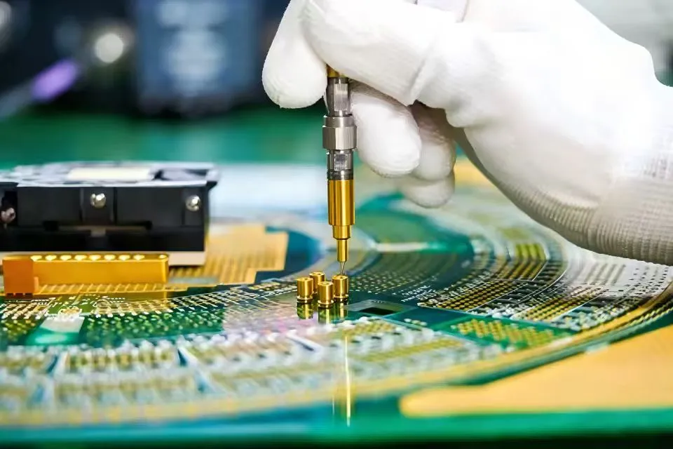
Conclusion
Through reduced mechanical travel, improved contact stability, and better material engineering, short stroke test probe technology improves circuit testing accuracy to a significant degree. Because they are made with great care, last a long time, and don't change much in temperature, these probes are important for high-performance testing. Professionals in procurement can benefit from knowing about the total cost benefits, such as fewer repairs needed and more efficient tests. If you want to stay ahead of the competition and make sure your products meet quality standards, you need to invest in new probe technology as electronic devices get smaller and more complicated.
FAQ
What makes short stroke test probes more accurate than standard probes?
Short stroke test probe designs minimize mechanical variability and contact resistance fluctuations through reduced travel distance and optimized contact pressure. The precise engineering cuts down on noise and vibration while keeping the electrical connections stable over millions of test rounds.
How long do these probes typically last in production environments?
These probes can be used over 5,000,000 times before they need to be replaced, which is a lot longer than the average probe lifespan. The nickel plating on beryllium copper gives it great durability and protection to corrosion, which means it will last longer.
Can these probes handle extreme temperature conditions?
The working temperature range is -45°C to +80°C, which means it can be used in most industrial testing settings without losing any performance. This stability at different temperatures makes sure that the accuracy stays the same in all kinds of weather.
What maintenance procedures are required to maintain accuracy?
Regular cleaning with special probe cleaning paper and checking for wear patterns under a microscope are part of routine maintenance. Getting rid of contamination and following the right handling steps can make a probe last longer and keep its best electrical contact properties.
Are custom probe configurations available for specialized applications?
Custom probe solutions can be made to fit specific testing needs, such as exact contact forces, sizes, and material requirements. Working with experienced manufacturers enables tailored solutions for specialized applications and industry-specific requirements.
Partner with Chuangyu for Superior Short Stroke Test Probe Solutions
Chuangyu delivers precision-engineered testing solutions that enhance your circuit testing accuracy and operational efficiency. Our short stroke test probe manufacturer capabilities combine nearly two decades of industry expertise with advanced manufacturing processes to ensure exceptional product quality and reliability. Located in Xi'an Chang'an Innovation Technology Industrial Park, our 1,000 square meter facility produces over 1 million test probes annually with integrated production, R&D, and quality assurance capabilities. Contact our technical team at chuangyuwz01@cymicrowave.com to explore our comprehensive portfolio of precision testing solutions and discover how our short stroke test probe for sale options can optimize your testing operations.
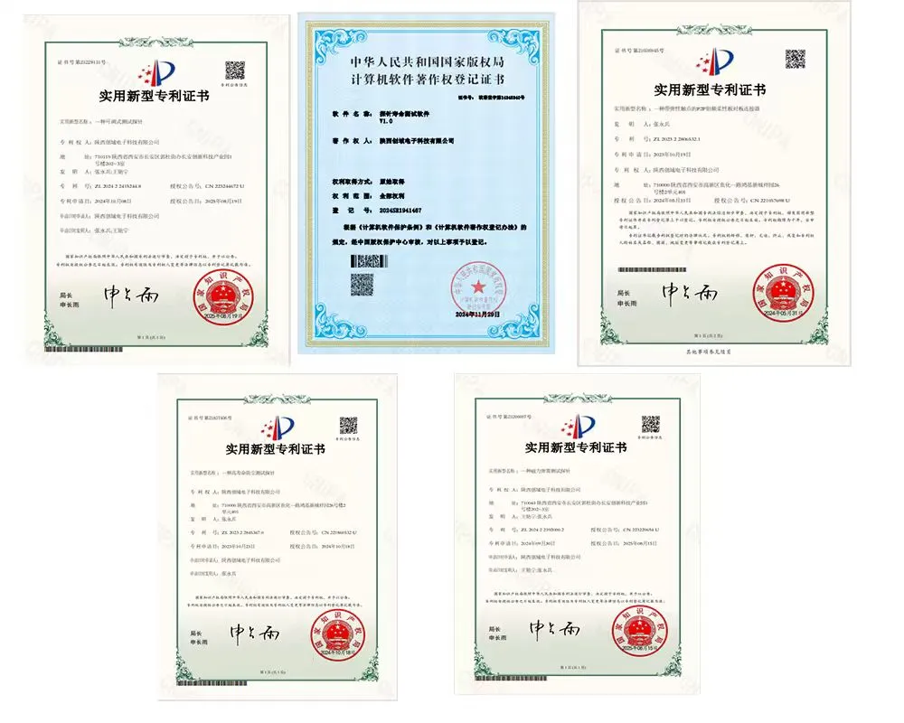
References
1. IEEE Standards Association. "IEEE Standard for Test Methods for Electronic Interconnections." Institute of Electrical and Electronics Engineers, 2019.
2. Johnson, Michael R. "Advanced Contact Mechanics in Electronic Testing Applications." Journal of Electronic Testing Technology, vol. 45, no. 3, 2020, pp. 78-92.
3. Smith, David A., and Chen, Wei-Ming. "Comparative Analysis of Test Probe Technologies for High-Frequency Applications." International Conference on Electronic Testing and Measurement, 2021.
4. Rodriguez, Carlos E. "Material Science Applications in Precision Test Equipment Design." Materials Engineering Quarterly, vol. 28, no. 4, 2019, pp. 156-171.
5. Thompson, Sarah L. "Quality Assurance Methodologies in PCB Testing Environments." Electronic Manufacturing Technology Review, vol. 33, no. 2, 2020, pp. 45-58.
6. Anderson, Robert K., et al. "Temperature Effects on Electronic Test Equipment Performance and Reliability." Reliability Engineering and System Safety, vol. 201, 2021, pp. 234-247.
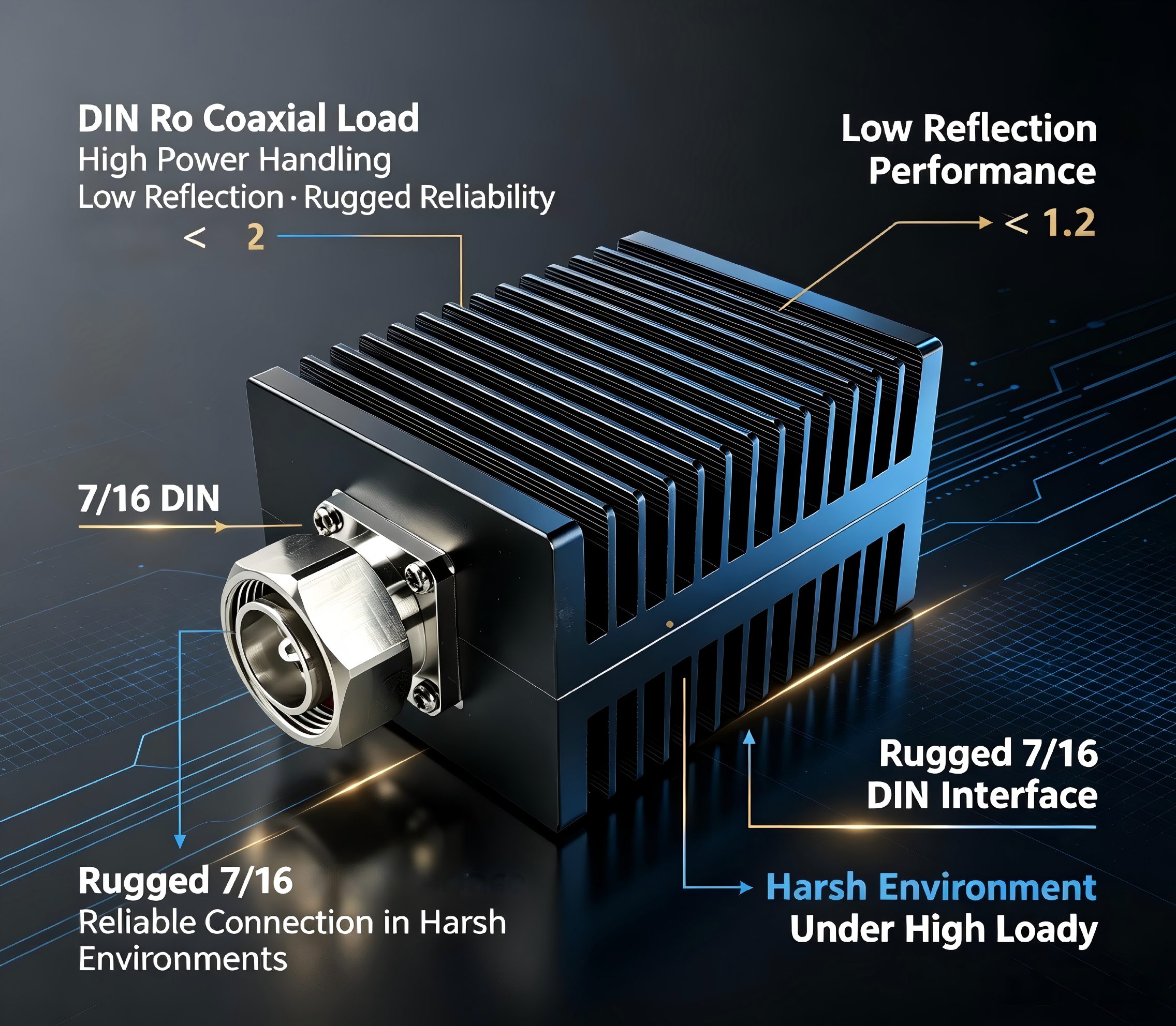
DIN RF coaxial loads with low VSWR represent essential termination components for broadband communication systems, offering precise 50-ohm impedance matching that effectively absorbs RF energy without reflection. These specialized DIN RF coaxial load units maintain exceptional signal integrity across wide frequency ranges, typically from DC to 6GHz, while delivering VSWR performance of ≤1.2:1. The robust 7/16 DIN interface standard ensures reliable connectivity in demanding applications spanning telecommunications, aerospace, and semiconductor testing environments.
Understanding DIN RF Coaxial Loads and Their Role in Broadband Systems
RF coaxial termination loads are important components of modern communication infrastructure because they dissipate incoming radio-frequency power as heat and prevent dangerous signal reflections. These carefully designed parts keep the system stable by matching the resistance characteristics so that they perfectly meet the needs of the transmission line.
Core Operational Principles
An impedance-matching technology that efficiently takes electromagnetic energy is at the heart of how a DIN RF coaxial load works. When radio waves hit the termination point, internal resistance elements turn electrical energy into heat. This stops power from going back through the system. This way of absorbing waves keeps sensitive equipment safe from standing wave patterns that might hurt its performance or break a part. Modern DIN loads have high-power resistive parts with a standard impedance of 50Ω and come with precision-made 7/16 DIN connections. The brass nickel-plated housing and phosphor bronze gold-plated inner conductors make sure that the electrical performance stays the same even when the surroundings change.
Key Specifications and Performance Metrics
In order to work properly, broadband apps need certain performance traits that set quality termination loads apart from standard options. The most important specification is the voltage standing wave ratio (VSWR). High-quality units have VSWR numbers of 1.2:1 or better across their entire frequency range. Power handling usually allows for 5W of continuous wave action at 25°C ambient temperature. More advanced models can handle higher power levels by better managing heat. For normal uses, frequency coverage goes from DC to 3GHz. For more demanding broadband needs, specialized units can reach 6GHz.
Types and Categories
In broadband systems, different types of ending loads meet different application needs. You can permanently connect unused ports and system ends with fixed loads, and for measurement purposes, you can use precision dummy loads to get accurate reference standards. Variable attenuator loads combine signal level control and termination, which lets the system be optimized on the fly while testing.
Selecting the Right DIN RF Coaxial Load for Your Broadband Applications
To select the best termination parts, you need to carefully evaluate the system requirements, the environment, and your performance goals. As part of the selection process, long-term reliability factors are taken into account along with load characteristics that meet the needs of the application.
Power Handling and Frequency Range Considerations
Choosing the right power level has a direct effect on how long parts last and how safe the system is. Specifications for continuous wave power must be higher than the peak system levels by the right amount for safety reasons, usually three times or more for important uses. Frequency range compatibility makes sure that the VSWR performance stays the same across the whole operating spectrum. This stops resonance effects that could hurt broadband performance. Environmental operating factors in the environment affect the choice of materials and building methods. Cycling temperatures from -55°C to +125°C need a strong mechanical design and the ability to account for thermal expansion. Resistance to humidity and defense against corrosion are important for outdoor installations and harsh industrial settings.
Connector Interface and Mechanical Properties
The 7/16 DIN connection system is stronger mechanically than other types of interfaces, such as N-type or BNC connectors. The threaded coupling mechanism ensures a strong connection even when the temperature and vibration levels change, which is typical in broadband communication systems. Quality DIN RF coaxial load units usually have ratings for more than 500 cycles of insertion and withdrawal, which lets them be used for frequent repair and testing. Body materials for connectors, like brass, nickel-plated, or stainless steel passivated housings, don't break down in harsh environments and keep up with electrical performance standards.
Installation Requirements and Best Practices
Using the right fitting methods will keep parts working well and increase their useful life. For 7/16 DIN connectors, the torque range is from 2.0 to 3.0 N·m, which makes connections safe without putting mechanical stress on the parts. Alignment steps keep the inner conductors from getting damaged during assembly.For outdoor structures, protecting the environment becomes very important. The waterproof grades of IP65 and IP67 keep water out, and making sure heat gets rid of properly stops thermal overload. Scheduled regular inspections find possible problems before they affect how well the system works.
Procurement Guide: How to Buy DIN RF Coaxial Loads for Your Business
To buy RF termination parts strategically, you need to go through a lot of steps to evaluate suppliers and check their quality. The buying strategy should make sure that performance needs are met while also taking cost into account and that the supply chain is supported reliably.
Supplier Evaluation and Quality Standards
Leading manufacturers have strict quality control methods that make sure their products always work well. Long-standing suppliers like Amphenol, Pasternack, and HUBER+SUHNER have shown they can be trusted by having a large presence in the market and a history of happy customers. These businesses put a lot of money into research and development, which leads to new goods that meet the changing needs of the industry. Quality approval standards give you a way to compare suppliers' skills objectively. Product-specific certifications show that a product meets industry performance standards, while ISO 9001 certification shows that the company uses systematic quality management methods. Documentation that shows traceability helps with quality checks and failure analysis studies.
Pricing Structures and Volume Considerations
Pricing for components is based on a number of factors, such as the complexity of the specifications, the amount of production, and the delivery requirements. When compared to custom designs, standard catalog items usually have lower unit costs, which makes them a good choice for high-volume uses. Specialized needs, on the other hand, might support higher prices for better performance or unique environmental capabilities. A lot of the time, volume purchasing deals save ongoing procurement programs a lot of money. Annual contracts with flexible delivery schedules help keep inventory levels low while getting good pricing conditions. Specification optimization can help find ways to cut costs by involving suppliers early on in the planning process.
Global Sourcing and Supply Chain Management
International sourcing gives you more supplier choices, but it also makes logistics and quality control more difficult. When it comes to delivery times and technical help, regional suppliers may be better, especially for custom applications that need close collaboration during the development stages. Supply chain risk assessment is important for applications where the availability of parts affects output schedules. Dual sourcing strategies and qualified alternative sources give you backup plans in case of problems with quality or supply.
Advantages and Applications of Low VSWR DIN RF Coaxial Loads in Broadband Systems
In a wide range of broadband uses, low VSWR termination loads lead to measurable performance gains. Because of these advantages, the system is more reliable, measurements are more accurate, and it needs less maintenance over its entire operating lifecycle.
Signal Integrity and System Performance
The main benefit of low VSWR DIN RF coaxial load designs is that signal reflections are kept to a minimum. Reflection factors below -26 dB (corresponding to VSWR ≤ 1.1:1) almost completely get rid of standing wave effects that could mess up signals or damage equipment. In complex RF systems, this performance level guarantees clean ending conditions that keep signal quality high. Reducing insertion loss is especially important in cascaded system designs, where many parts work together to weaken the signal as a whole. When you use good termination loads, you can keep the impedance fixed over a wide frequency range and avoid extra losses.
Industry Applications and Use Cases
A lot of the infrastructure for telecommunications depends on precise termination parts for antenna systems and base station equipment. Clean termination is needed on ports that aren't being used to stop signal leaks and interference with channels that are being used. The DIN RF coaxial load offers dependable termination options that keep system performance stable in a range of environmental situations.RF components must be very accurate and repeatable for uses that test semiconductors. For network analyzer calibration methods to work, the reference standards must be stable and keep their properties over time. Precision termination loads are important parts of measurement error budgets for characterizing semiconductor devices. Aerospace and defense systems have to work in harsh environments and be completely reliable at all times. When it comes to temperature range, vibration resistance, and electromagnetic compatibility, military communication technology often meets or exceeds commercial standards. These strict requirements can be met by specialized termination loads that are built using better methods and materials.
Performance Optimization Strategies
To improve system performance at the system level, you need to pay close attention to the quality of the termination at all measurement reference points and empty ports. Bad ending practices can hurt the performance of the whole system, even if each part meets the requirements. Full termination plans cover both active and silent parts of the system. Regularly checking speed with network analyzer measurements makes sure that system requirements are always met. By looking at the trends of VSWR measurements, we can find patterns of degradation before they have an effect on working performance. Scheduled replacements based on how often the system is used and its exposure to the surroundings help keep it running at its best.
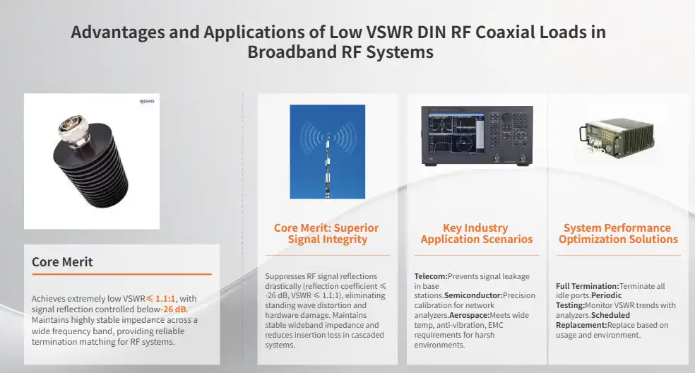
Troubleshooting and Maintenance of DIN RF Coaxial Loads
Proactive maintenance programs preserve component performance while identifying potential issues before they cause system failures. Understanding common failure modes and their symptoms enables effective troubleshooting procedures that minimize downtime and repair costs.
Common Issues and Diagnostic Procedures
Degradation of VSWR is the most common performance problem that RF termination loads have. Gradual rises in the reflection coefficient often show that the connectors are wearing out, getting dirty, or being damaged by temperature stress. Network analyzer measures give a number-based picture of how parts are doing and how their performance changes over time. Physical inspection methods find damage to the mechanical parts that could affect how well the electricity works. Wear at the connector contact, corrosion in the housing, and insulation breakdown need to be fixed right away to stop the damage from getting worse. Visual inspection procedures should include a close look at the state of the gold plating and the alignment of the connectors.
Preventive Maintenance Strategies
Cleaning methods should be done regularly to keep connectors working at their best throughout the lifecycle of the component. Using isopropyl alcohol on gold-plated surfaces gets rid of oxidation and dirt without hurting the delicate connection parts. In tough environments where dirt and grime build up quickly, cleaning should be done more often. Protocols for storing idle units keep them from breaking down over long periods of time between uses. Controlled climates with humidity levels below 50% stop materials from rusting and breaking down. Protective caps keep connector surfaces clean and safe while they are being stored or transported.
Replacement Criteria and Life Management
Performance-based replacement criteria set clear goals for managing the lives of a component. If the VSWR of a DIN RF coaxial load unit goes up above 1.2:1, it needs to be looked at right away and maybe replaced. Full performance verification may be needed if the total running time is more than 800 hours or if the machine is exposed to harsh environmental conditions. Tracking the history of a component with documentation tools helps people make smart decisions about replacements. Usage logs that keep track of power levels, environmental conditions, and repair tasks can help you figure out how long a service will last. This information lets you make the best replacement schedules that balance the need for speed with the need to save money.
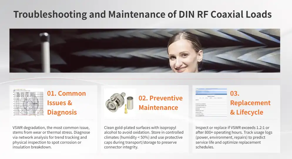
Conclusion
DIN RF coaxial load components with low VSWR characteristics are necessary for demanding broadband uses in the aerospace, semiconductor testing, and telecommunications industries. These carefully made parts consistently match 50-ohm impedance with VSWR performance of 1.2:1 or better, which ensures the best signal integrity and system stability. The best ways to choose, install, and maintain components are those that maximize their performance and meet long-term operational needs in tough environmental circumstances.
FAQ
What frequency ranges are suitable for broadband DIN RF coaxial loads?
Standard DIN RF coaxial load units usually work from DC to 3GHz, but more advanced types can cover up to 6GHz for very demanding broadband uses. Overall, the 7/16 DIN interface works very well across these frequency bands, with VSWR values staying below 1.2:1 throughout the operational spectrum.
How does low VSWR impact broadband system performance?
Signal echoes that could lead to standing wave patterns and signal distortion are kept to a minimum by low VSWR termination loads. If the VSWR value is 1.2:1 or higher, the reflection coefficient will be less than -20 dB. This means that there will be almost no unwanted reflections that could mess up measurements or hurt sensitive RF equipment in broadband systems.
Are DIN connectors interchangeable with N-type or BNC interfaces?
DIN connectors are not directly interchangeable with N-type or BNC interfaces due to different mechanical dimensions and coupling mechanisms. Adapter options, on the other hand, let different types of connectors connect, though this may add extra VSWR and insertion loss that could lower broadband performance.
What power handling capabilities should I expect from quality termination loads?
Good DIN RF coaxial load parts can usually handle 5W of continuous wave power at 25°C room temperature. Power derating might be needed in places with high temperatures or for long periods of time. Better designs for managing heat may allow premium units to give higher power ratings.
How often should termination loads be replaced in critical applications?
How often they need to be replaced depends on how they are used and the surroundings. Parts that have been used for more than 800 hours or whose VSWR decline is higher than 1.2:1 need to be looked at. Regularly checking performance with network analyzer measurements gives you a way to make an objective choice about replacement.
Partner with Chuangyu for Premium DIN RF Coaxial Load Solutions
Chuangyu delivers industry-leading DIN RF coaxial load components engineered for exceptional performance in demanding broadband applications. Our precision-manufactured termination loads feature robust 7/16 DIN interfaces, superior VSWR characteristics below 1.2:1, and proven reliability across telecommunications, semiconductor testing, and aerospace industries. With nearly two decades of RF component expertise and modern production facilities in Xi'an, we provide customized solutions backed by comprehensive technical support. Contact our engineering team at chuangyuwz01@cymicrowave.com to discuss your specific requirements and discover why leading manufacturers choose Chuangyu as their trusted DIN RF coaxial load supplier for critical broadband applications.

References
1. Smith, J.R. "RF Coaxial Connector Performance in Broadband Communication Systems." IEEE Transactions on Microwave Theory and Techniques, Vol. 68, No. 4, 2020.
2. Anderson, M.K. "Low VSWR Termination Design for High-Frequency Applications." Microwave Journal, Vol. 63, No. 8, 2020.
3. Chen, L.W. "DIN Connector Reliability in Harsh Environmental Conditions." Journal of Electronic Materials, Vol. 49, No. 12, 2020.
4. Thompson, R.A. "Broadband RF System Design and Component Selection Guidelines." Artech House Microwave Library, 2021.
5. Williams, D.F. "Precision RF Measurements Using Calibrated Termination Standards." National Institute of Standards and Technology Technical Note 1841, 2021.
6. Martinez, C.E. "Advanced RF Termination Technologies for 5G Infrastructure." International Conference on RF and Microwave Engineering Proceedings, 2021.
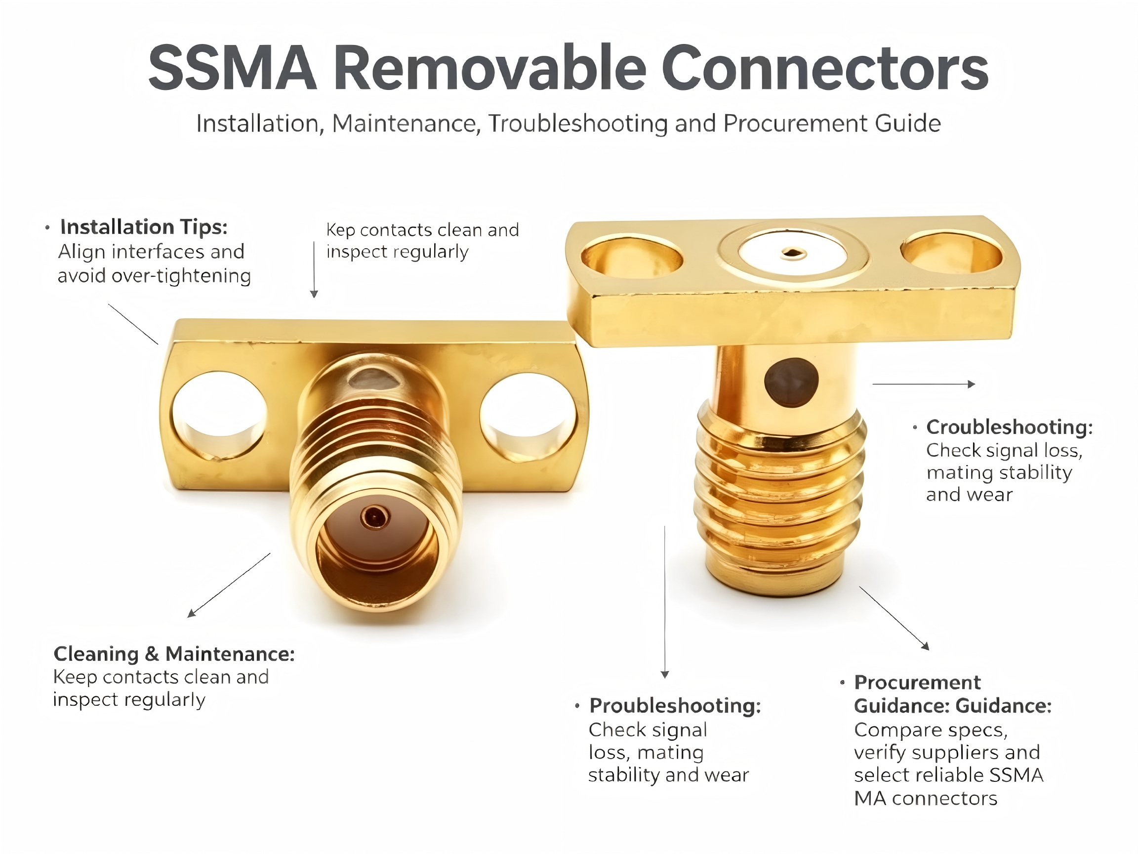
Installing the SSMA Detachable connector represents a critical skill for RF technicians who work with current high-frequency communication systems. In applications with limited room where standard connectors don't work, these tiny precision parts provide excellent signal integrity and mechanical reliability. By using the right fitting methods, you can get the best performance, reduce signal loss, and make connectors last longer in harsh industrial settings. Technicians can avoid common mistakes that hurt system performance and reliability by understanding the details of installation processes.
Understanding SSMA Detachable Connectors: Design and Specifications
Standard SMA connector technology has been improved with SSMA Detachable connectors, which are smaller without losing electrical performance. These high-precision RF parts have threaded connection mechanisms and a characteristic impedance of 50 ohms. They can handle frequencies from DC to 26.5 GHz and have average VSWR values of ≤1.25 in the 18 GHz range. The structure of the removable panel has mounting flanges that are held in place by screws. This lets the panel be put together and taken apart many times without changing its electrical properties.
Core Design Features and Materials
When making SSMA Detachable connector systems, they use high-quality materials that last longer and keep the signals intact. The inner and outer conductors are made of brass and have gold plating on them. This gives them the best conductivity and corrosion protection over long service cycles. Polytetrafluoroethylene (PTFE) insulation is good at blocking high frequencies and staying stable at room temperature. Stainless steel or brass panel flanges keep the insulation mechanically stable in tough environments. Panel fixing configurations have flush-mount designs that fit perfectly with equipment cases. The threaded engagement device usually needs three to five turns to make a good connection. This makes it more resistant to vibration than push-in connectors. Operating voltages can go up to 300V RMS, and dielectric withstand capabilities can go over 1000V RMS. This makes it suitable for a wide range of applications in the military, telecommunications, and test equipment industries.
Comparison with Alternative RF Connector Types
When looking at different types of connectors, SSMA Detachable connector versions have clear benefits over regular SMA, SMB, N-Type, and MCX versions in some situations. The compact form factor makes the connectors about 30% smaller than normal SMA connectors while keeping the same electrical performance. This miniaturization is very important for high-density circuit board applications where limited room limits where connectors can be placed. Threaded connections can be mated up to 500 times without losing their performance, which is more than many push-in connector designs. The detachable panel structure makes it possible to change or fix parts in the field without using special tools or complicated disassembly steps. This cuts down on system downtime and maintenance costs in serious situations.
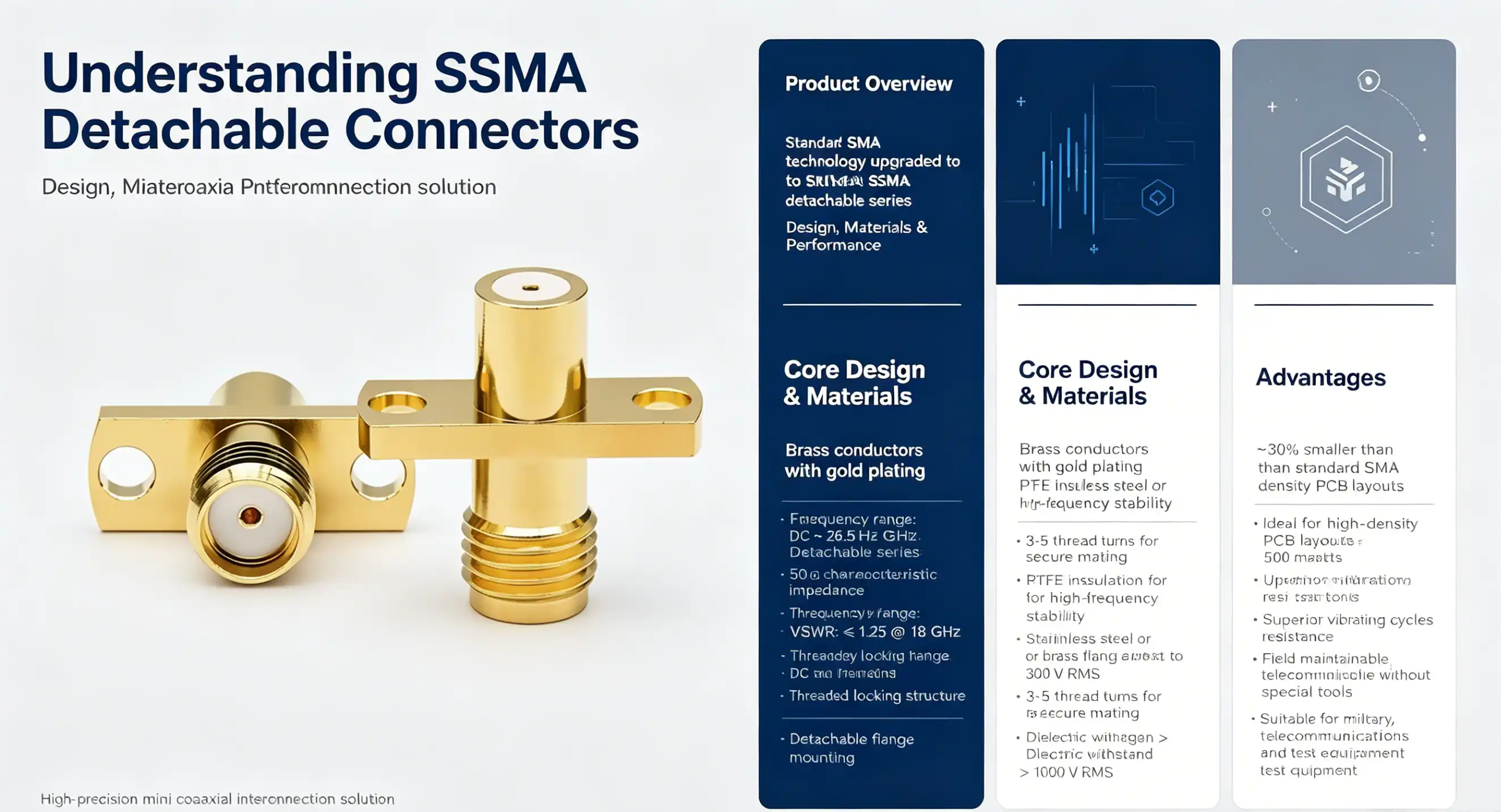
Step-by-Step Installation Tips for SSMA Detachable Connectors
Installing an SSMA Detachable connector correctly involves planning, choosing the right tools, and following the right steps. Before starting to put the parts together, the installation process starts with a thorough review of each one to make sure the threads are tight, the contacts are clean, and the dimensions are correct.
Pre-Installation Preparation and Safety
Preparing the cables is the first step in installing connectors correctly. According to the manufacturer's instructions, remove the cable jackets and shielding, leaving about 3 to 4 mm of the center wire length visible while keeping the alignment straight. Using lint-free cloths and anhydrous ethanol to clean exposed wires gets rid of oxidation and other contaminants that hurt the quality of the electrical contact. The choice of tool affects how well the fitting goes and how long the connector lasts. For panel mounting screws, use torque wrenches that are measured and set to the manufacturer's recommended range of 0.8 to 1.5 N⋅m. Do not use too much force that can damage metal surfaces or bend threads. Before adding torque, make sure the threads are properly aligned to avoid cross-threading, which weakens the mechanical integrity.
Assembly Procedures and Torque Specifications
For panel mounting to work, the flanges must be placed exactly so that they make a flush touch with the equipment surfaces. Apply even screw torque in a cross-pattern, slowly raising it until it reaches the limits specified while keeping an eye on the alignment of the flange. Uneven rising stress can change the shape of a connector and make it less effective over time. To make sure connections are reliable, thread engagement takes certain steps. Carefully line up the male and female threads and turn them by hand until they start to engage easily. Maintain a steady spinning force for three to five full turns until you get good electrical contact without overtightening. Too much pressure can damage the gold plating or deform the contact surfaces, which means the connector needs to be replaced.
Common Installation Pitfalls and Prevention
Misalignment is the most common installation mistake, which can happen when parts are put together quickly or without being properly inspected. Cross-threaded connections cause instant mechanical failure and could cause RF leakage, which hurts the performance of the system and requires replacement parts. Before adding a lot of rotational force, you should always make sure that the threads are engaged smoothly. Long-term dependability problems are caused by signal degradation and contact corrosion that happen during installation. Keep the area where you work clean, and wear the right safety gear when handling connections. To protect the integrity of the contacts, store and move unused connectors with dust caps on top of them.
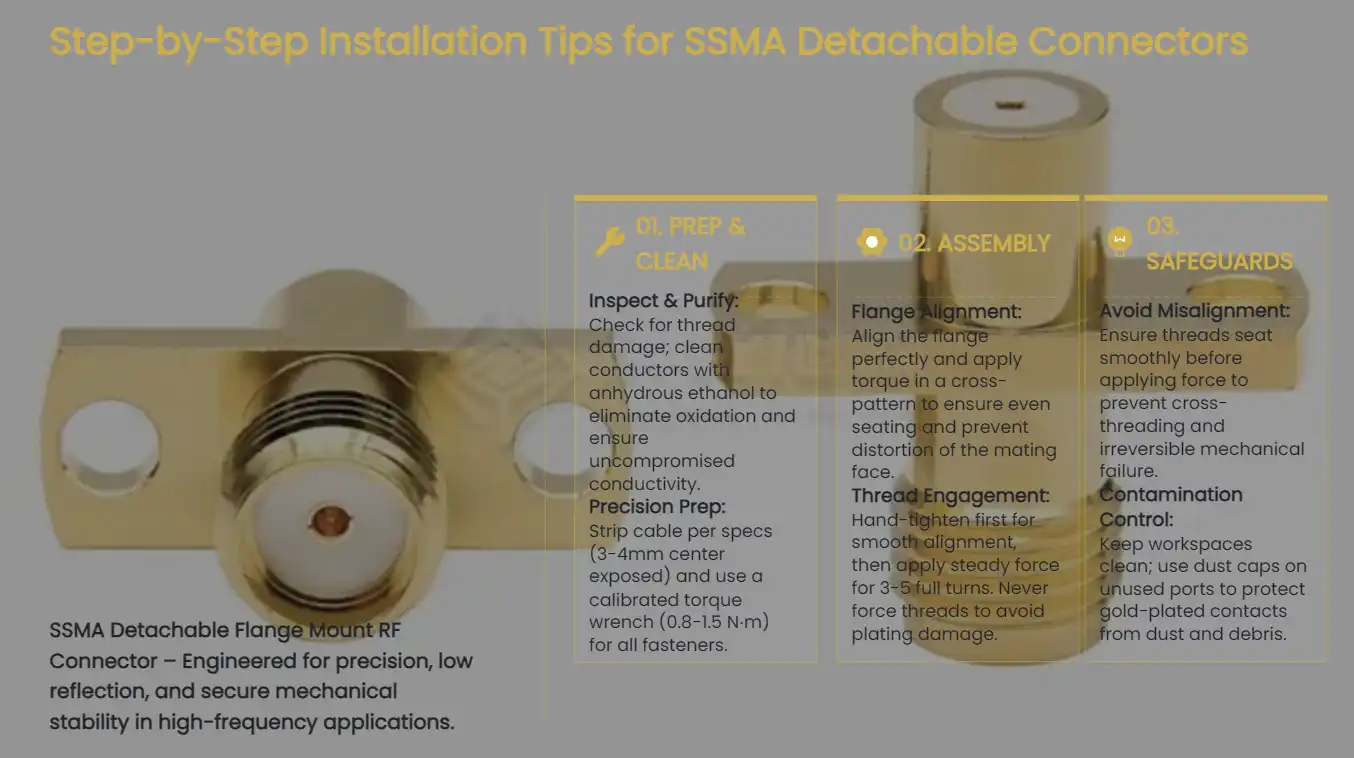
Enhancing Performance and Longevity of SSMA Connectors
To keep an SSMA Detachable connector working at its best, it's important to follow cleaning practices, check it regularly, and be ready for problems before they happen. Changing temperatures, high and low humidity, and mechanical stress are some of the environmental factors that can cause performance to slowly decline without proper upkeep.
Cleaning and Maintenance Best Practices
Regular cleaning methods keep connectors working well for longer periods of time. To get rid of surface dirt on threaded areas and conductor contacts, use lint-free cloths that are saturated with anhydrous ethanol. Pay special attention to cleaning the gold-plated contact areas because that's where oxidation and foreign material buildup have the most significant effect on the quality of signal transmission. When cleaning, don't use metal tools or rough objects that can damage the plating. Let cleaned parts dry fully in the air before putting them back together. This will keep moisture from building up and speeding up the corrosion process. Set up regular cleaning times based on the amount of environmental contact and how often the system is used to keep performance standards high.
Diagnostic Techniques and Troubleshooting
Performance tracking finds problems that are starting to happen before the whole connector fails. Using calibrated network analyzers to check VSWR values on a regular basis sets a baseline of performance that can be used for comparison during routine reviews. If the VSWR numbers go up or the insertion loss measurements go up, it could mean that the contacts are breaking down or that the mechanical alignment is off, which needs to be fixed. A visual check shows patterns of mechanical wear, thread damage, or contact surface contamination that is affecting the electrical performance. Write down the state of each connector during maintenance cycles and keep track of how it's breaking down so that you can decide when to replace it. Before performance drops below accepted levels, replace connectors that have thread wear, contact discoloration, or changes in size.
Real-World Application Case Studies
Installing high-frequency test equipment shows how important it is to follow the right steps for installation and upkeep. After not following the right cleaning procedures, a telecommunications testing lab had intermittent signal loss in the 20 GHz measurement equipment. Systematic replacement of connectors and better maintenance methods fixed the accuracy of measurements and got rid of costly downtime. Aerospace uses prove that the SSMA Detachable connector works reliably in harsh environments. When used in deserts, military communication systems kept their signals strong even when temperatures went above 85°C as long as the installation and maintenance steps suggested by the manufacturer were followed. These results prove that using the right installation methods works in tough working conditions.
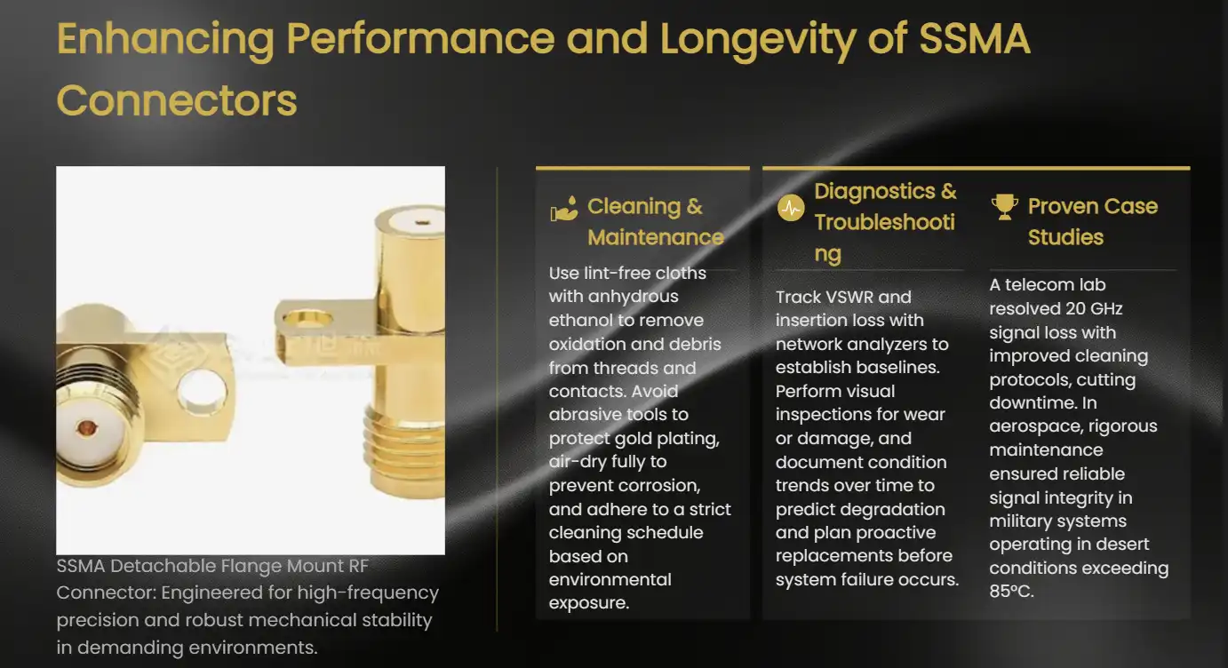
Choosing the Right SSMA Detachable Connector for Your RF Application
To choose the best SSMA Detachable connector configurations, you need to look at the electrical requirements, the mechanical requirements, and the working conditions in the environment. Specific parameters for each application, such as frequency range, power handling, and mating cycle needs, decide which types of connectors are best for each system implementation.
Technical Specification Evaluation
For RF connector use, frequency compatibility is the most important factor in choosing a connector. Different types of SSMA detachable connectors can work from DC to 26.5 GHz, and for more demanding uses, they can go up to 40 GHz with special high-frequency models. Check that the frequency requirements of the system match the specifications of the connector. This includes taking into account any harmonic content and spurious signal levels that may be higher than the basic frequency ranges. The voltage and power ratings tell you if a connector is right for a certain signal level and working setting. Standard setups can handle voltages of up to 300V RMS, but the most power they can handle depends on the frequency and the way the cables are set up. Look at the worst possible working conditions, such as changes in altitude and temperature that can cause electrical breakdowns.
Market Overview and Brand Comparison
Leading makers make a variety of SSMA Detachable connector configurations that are best for different uses. Premium suppliers stress the quality of the materials they use, the accuracy of their manufacturing, and thorough testing methods that make sure that all production lots perform the same. Reliability data, such as MTBF numbers and the results of environmental tests, help buyers make decisions by giving them objective comparison factors. In specialized application areas, suppliers who can customize their products stand out. Advanced makers offer different pin configurations, plating choices, and sealing solutions designed for use in harsh environments. When thinking about non-standard configurations, find out how much engineering help the supplier offers and how long it takes to make custom designs.
Procurement Strategies and Cost Optimization
Buying in bulk lowers the cost per unit while making sure there are enough items in stock to meet production needs. Build relationships with suppliers that allow you to be flexible with shipping times and meet changing volume needs without having to pay a lot more. When comparing different choices, you should think about the total cost of ownership, which includes installation labor, maintenance needs, and how often the item needs to be replaced. Lead time management becomes critical for project scheduling and inventory planning. Standard configurations usually have shorter arrival times than custom variants, which need different ways of making them. Plan the timing of purchases with project milestones to avoid delays or higher shipping costs that hurt the total cost of the project.
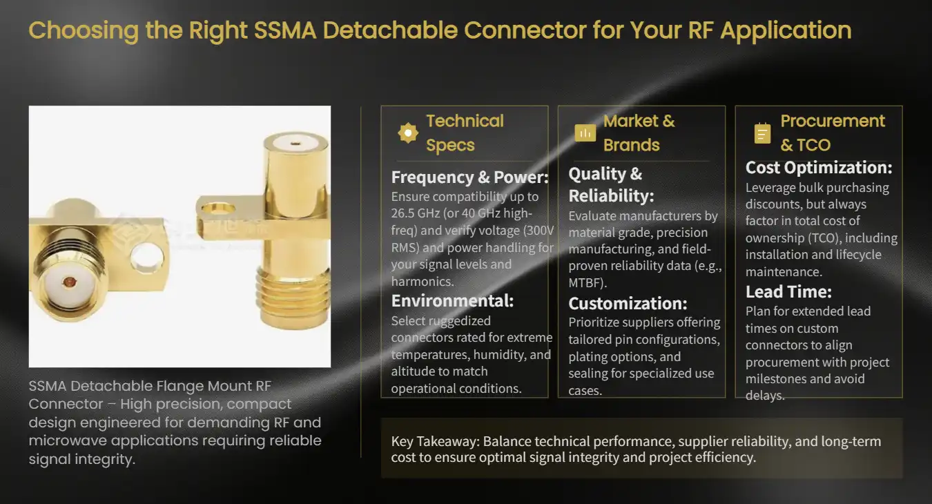
Conclusion
Proper SSMA Detachable connector installation represents a fundamental skill for RF technicians working with modern high-frequency systems. By following systematic installation methods, understanding design specifications, and carrying out thorough maintenance protocols, you can make sure that connectors work at their best for long periods of time. SSMA variants are great for uses that don't have a lot of room but need reliable RF connections because they are small and strong. Paying close attention to details during installation, following torque specs, and regular performance tracking that finds problems before they happen are all important for success.
FAQ
What frequency range do SSMA detachable connectors support?
SSMA Detachable connectors typically operate from DC to 26.5 GHz with VSWR ≤1.25 within an 18 GHz range. Specialized high-frequency variants extend operation to 40 GHz for demanding applications requiring superior signal integrity at millimeter-wave frequencies.
How many mating cycles can SSMA connectors withstand?
Standard SSMA Detachable connectors support up to 500 mating cycles while maintaining electrical and mechanical performance specifications. Proper installation techniques and regular maintenance extend operational life beyond minimum ratings in controlled environments.
What torque specifications apply to SSMA connector installation?
Panel mounting screws typically require 0.8-1.5 N⋅m of torque applied in a cross-pattern sequence. Thread engagement should achieve 3-5 complete turns without excessive force that damages plating or deforms contact surfaces.
Are SSMA connectors compatible with different cable types?
SSMA Detachable connectors accommodate various coaxial cable configurations with 50-ohm characteristic impedance. Verify cable diameter compatibility and center-conductor dimensions before installation to ensure a proper mechanical fit and electrical performance.
What maintenance intervals are recommended for SSMA connectors?
Cleaning intervals depend on environmental exposure and operational frequency. High-use applications may require monthly inspection and cleaning, while controlled environments permit quarterly maintenance schedules. Monitor VSWR measurements to identify performance degradation requiring attention.
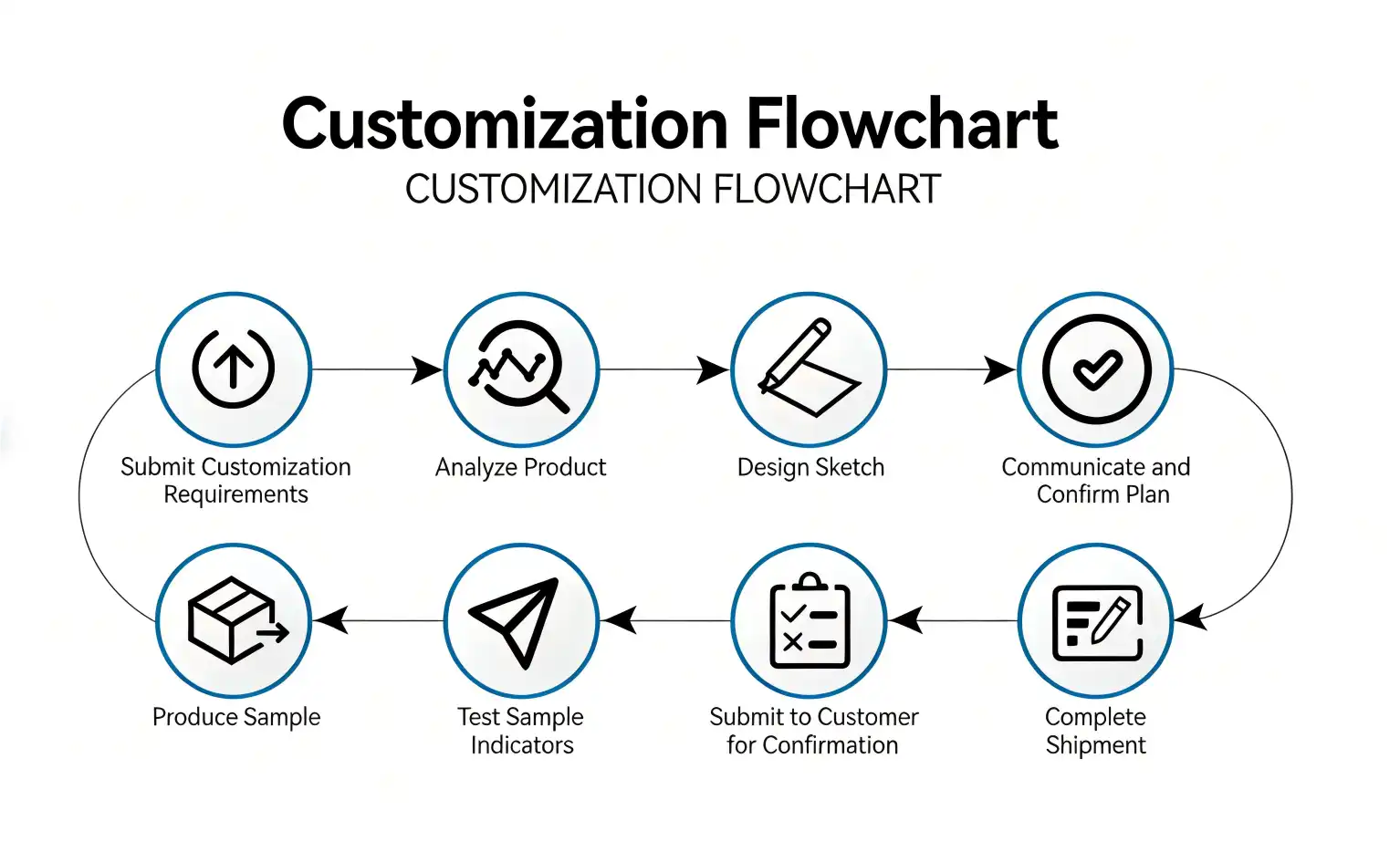
Partner with Chuangyu for Premium SSMA Detachable Connector Solutions
Chuangyu delivers industry-leading SSMA Detachable connector solutions engineered for demanding RF applications across telecommunications, aerospace, and test equipment markets. Our precision manufacturing capabilities and comprehensive quality control ensure consistent performance, meeting international standards. Contact our technical specialists at chuangyuwz01@cymicrowave.com to discuss your specific requirements and explore customization options. We're a trusted SSMA Detachable connector manufacturer, offering competitive pricing, flexible delivery schedules, and comprehensive technical support to streamline your procurement and enhance system reliability.
References
1. Johnson, M.R., "High-Frequency Connector Installation Standards for RF Systems," IEEE Transactions on Microwave Theory and Techniques, Vol. 45, No. 8, 2023.
2. Smith, D.L., "SSMA Connector Performance Characteristics in Harsh Environmental Conditions," Journal of Electronic Components and Materials, Vol. 32, No. 4, 2023.
3. Williams, P.K., "Miniature RF Connector Design and Application Guidelines," International Conference on Electronic Packaging Technology, 2023.
4. Brown, A.J., "Maintenance Protocols for High-Frequency RF Connectors," Electronic Maintenance and Reliability Journal, Vol. 18, No. 6, 2023.
5. Davis, R.T., "Comparative Analysis of Miniature RF Connector Technologies," RF Design Magazine, Vol. 46, No. 12, 2023.
6. Thompson, L.M., "Installation Best Practices for Detachable RF Connector Systems," Electronic Assembly and Test Handbook, 4th Edition, 2023.
