- English
- French
- German
- Portuguese
- Spanish
- Russian
- Japanese
- Korean
- Arabic
- Greek
- German
- Turkish
- Italian
- Danish
- Romanian
- Indonesian
- Czech
- Afrikaans
- Swedish
- Polish
- Basque
- Catalan
- Esperanto
- Hindi
- Lao
- Albanian
- Amharic
- Armenian
- Azerbaijani
- Belarusian
- Bengali
- Bosnian
- Bulgarian
- Cebuano
- Chichewa
- Corsican
- Croatian
- Dutch
- Estonian
- Filipino
- Finnish
- Frisian
- Galician
- Georgian
- Gujarati
- Haitian
- Hausa
- Hawaiian
- Hebrew
- Hmong
- Hungarian
- Icelandic
- Igbo
- Javanese
- Kannada
- Kazakh
- Khmer
- Kurdish
- Kyrgyz
- Latin
- Latvian
- Lithuanian
- Luxembou..
- Macedonian
- Malagasy
- Malay
- Malayalam
- Maltese
- Maori
- Marathi
- Mongolian
- Burmese
- Nepali
- Norwegian
- Pashto
- Persian
- Punjabi
- Serbian
- Sesotho
- Sinhala
- Slovak
- Slovenian
- Somali
- Samoan
- Scots Gaelic
- Shona
- Sindhi
- Sundanese
- Swahili
- Tajik
- Tamil
- Telugu
- Thai
- Ukrainian
- Urdu
- Uzbek
- Vietnamese
- Welsh
- Xhosa
- Yiddish
- Yoruba
- Zulu
knowledge
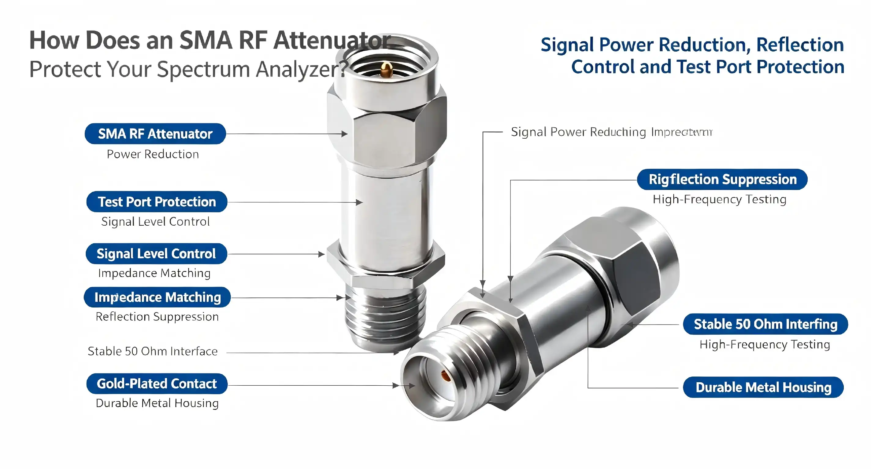
An SMA RF attenuator protects your spectrum analyzer by reducing excessive signal power before it reaches the instrument's sensitive input stage. This critical component prevents front-end damage caused by overload conditions while preserving signal integrity and measurement accuracy. By inserting controlled attenuation between the signal source and analyzer, these devices ensure your equipment operates within safe power limits, extending service life and maintaining calibration stability across demanding RF testing environments.
Why Protecting Your Spectrum Analyzer Is Critical
Vulnerability of Precision Measurement Systems
For high-performance types, spectrum analyzers often cost more than six figures, which is a lot of money. Low-noise amplifiers, mixers, and local oscillators are some of the sensitive front-end parts in these instruments that are made to pick up sounds at microvolt levels. When too much power comes in through the input port, damage happens quickly. In a single overload event, amplifiers can be burned out, mixer diodes can be destroyed, and input circuits can become damaged. Repairs often cost more than a few thousand dollars, and that doesn't include the time that the machine is down, which affects production plans and testing processes.
Real-World Damage Scenarios
Take a look at a 5G base station test case where the transmitted power is +43dBm (20 watts). Connecting this signal directly to an analyzer that can handle a maximum input level of +30dBm will fail right away if you don't use the right SMA RF attenuator. The front-end parts can't get rid of the extra energy, so within milliseconds, thermal damage happens. Over time, even signals that are below the exact maximum ratings can cause slow degradation, which can change the calibration and make measurements less accurate.
Measurement Integrity Preservation
In addition to protecting against damage, SMA RF attenuators keep the standard of measurements. When signals coming into an analyzer get close to its compression point, nonlinear distortion shows up in the spectra that are shown. Harmonics and intermodulation products that weren't in the original signal can be seen all of a sudden, which can lead engineers to come to the wrong conclusions about how well the device is working. Bringing signal levels down to the instrument's linear operating range makes sure that what you measure is a good representation of what you're testing.
Long-Term Asset Management
The economics of a lab are directly affected by how long the equipment lasts. When an SMA RF attenuator is used correctly, it protects analyzers so they stay in factory specs for longer, need to be calibrated less often, and show better measurement repeatability. When procurement teams look at the total cost of ownership, instruments that are properly protected give a better return on investment because they last longer and cost less to maintain.
Key Performance Factors When Choosing an SMA RF Attenuator
Frequency Range Matching
The SMA RF attenuator must have a frequency range that works with your application. A device that is designed to work at 18GHz doesn't work well at 26GHz, which leads to measurement errors because of higher insertion loss and VSWR degradation. When testing new 5G devices that work in millimeter-wave bands, it is important to choose parts that are rated for extended frequency coverage. Mismatched frequency response leads to regular mistakes that weaken the validity of the test, which could mean that compliant devices fail qualification or defective units pass.
Power Handling Capacity
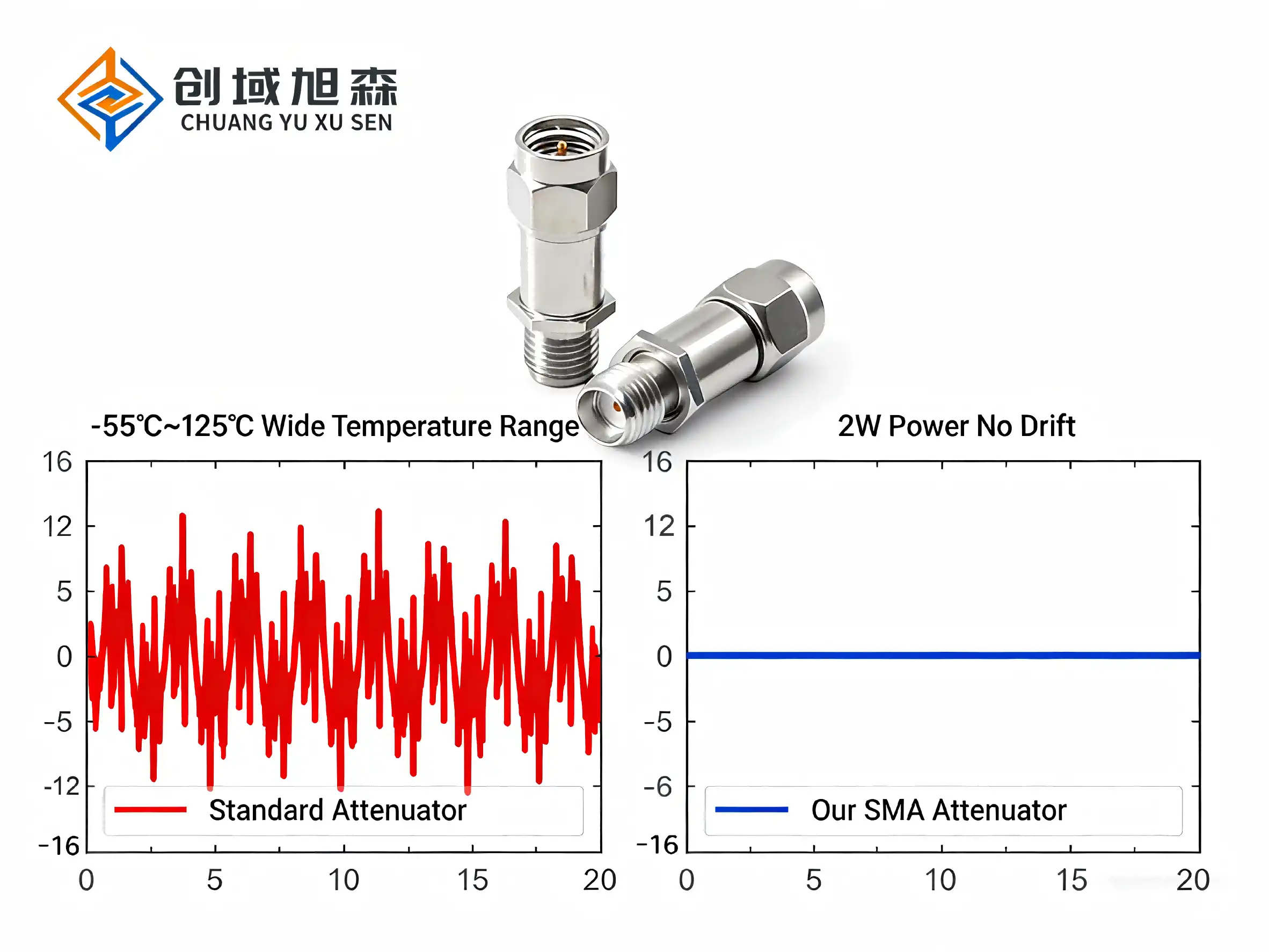
Average power ratings set the limits for constant operation, while peak power ratings deal with pulsed signals that are common in tests for radar and telecommunications. A 2W average power SMA RF attenuator can handle steady-state conditions like those found in continuous-wave tests, but peak power capability needs to be thought about for pulse uses. The 0.1kW peak grade and set pulse width and duty cycle factors make sure that parts can handle sudden changes without breaking. To make sure there is enough safety margin, engineers have to figure out the actual power levels at the attenuator, taking into account cable losses and the source's characteristics.
Impedance Characteristics and VSWR
For test tools, all RF systems use a 50Ω resistance, but there are also 75Ω systems used for video distribution. Reflections that mess up measurements can be avoided by making sure that the impedance stays the same throughout the signal chain. VSWR measures how well the resistance matches. For example, a VSWR of 1.2 means that only 4.3% of the power that hits the load is reflected back toward the source. Lower VSWR values lower the uncertainty of measurements and shield signal sources from reflected energy that might change the stability of output. Good SMA RF attenuators keep the VSWR at a certain level across their whole frequency range, not just at certain frequencies.
Attenuation Accuracy Considerations
When adjusting systems or checking gadget specs, accuracy is important. Every measurement is skewed by 0.7dB when an SMA RF attenuator that says "10dB" but only gives 9.3dB actually does. This mistake spreads through calculations when testing amplifier gain or filter insertion loss, and it could lead to specification failures. Tight tolerances—±0.5dB for lower values and ±1dB for higher attenuation—ensure that the measurements are accurate. Regular checks with precise network monitors make sure that performance stays within the component's limits for as long as it's used.
Comparing SMA RF Attenuators with Other Types for Spectrum Analyzer Protection
SMA Versus BNC Configurations
During the 1990s, BNC connectors were the most common type used for RF testing. However, they have a lot of problems above 4GHz. Even though their bayonet connection method is handy, it creates impedance discontinuities that make VSWR and insertion loss worse at higher frequencies. Engineers who work with older equipment below 1GHz can get by with BNC units, but modern wireless communications, satellite systems, and radar applications need SMA RF attenuator performance. Because SMA connectors' threaded coupling makes them more mechanically stable and electrically consistent, they are commonly used in modern test environments.
N-Type Alternatives
N-type connectors can handle a lot more power—often 100W or more—which makes them good for testing transmitters and figuring out what high-power amplifiers are made of. Because they are bigger, they can hold bigger center conductors and get rid of heat better. This small size advantage isn't so great in small test sets or when working above 18GHz, though. N-type SMA RF attenuators work best in situations where power handling is more important than frequency expansion, while SMA configurations are best for installations that need to cover a wide frequency range but don't have a lot of room.
2.4mm and 1.85mm Precision Connectors
When testing goes beyond 26GHz and into millimeter-wave frequencies, you need 2.4mm connectors that can handle 50GHz and 1.85mm connectors that can handle 67GHz. For these precise connections to work, they need to be handled with great care. They need to be installed in a clean room and must be carefully checked before each link. They let you measure things that you can't do with regular SMA RF attenuator parts, but they usually cost three to five times as much. Procurement planning tools aren't general-purpose answers because they aren't always available and wait times are long.
Performance-Cost Trade-Offs
SMA RF attenuators from less well-known brands can be as cheap as $30 to $50, while high-quality models from well-known names can cost $200 to $400. This difference in price is due to manufacturing tolerances, the quality of the materials, and performance testing. When the frequency limits get close, cheap parts often have worse VSWR, bigger loss tolerances, and less power handling. People who work in procurement have to weigh the benefits of short-term cost savings against the need for long-term dependability and measurement confidence. Protecting six-figure instruments should be done with tried-and-true parts that have been tested and come with maker support.
Procurement Insights for SMA RF Attenuators in B2B Contexts
Supplier Evaluation Criteria
To find reliable suppliers of SMA RF attenuators, you need to look at more than just the unit price. Manufacturing skills are important. Suppliers who do their own production can better control quality than brokers who get their supplies from different subcontractors. Ask for details about the places where the products are made, the systems used to manage quality, and the testing methods used. Established providers keep full test records for every production lot. This allows for tracking that meets the standards of ISO 9001 and AS9100, which are popular in aerospace and defense uses.
Pricing Structures and Volume Considerations
When a lot of units are ordered, the unit price goes down a lot. One SMA RF attenuator could cost $150, but if you buy 100 of them, the price could drop to $85 each, a 43% cut. Setting up yearly purchase deals that lock in good prices and guarantee the supply of parts is good for OEM integrators and contract makers. Some suppliers have consignment inventory programs that put stock at customer facilities to help with just-in-time manufacturing. The supplier doesn't actually own the goods until they are used. These plans make the best use of working capital while keeping output going.
Lead Time Management
Standard catalog items usually ship within one to two weeks, but it can take up to eight weeks for items with custom SMA RF attenuator values, specialized frequency ranges, or different connector genders to arrive. As engineers finish up their designs for test systems, they should work with procurement teams right away to find long-lead parts that could affect project schedules. Building ties with suppliers who keep a good supply of popular configurations in stock gives you options when needs change at the last minute or equipment breaks down and needs to be replaced right away.
Customization Capabilities
Standard product lines cover most common uses, but unique SMA RF attenuator solutions are often needed for testing that is very specific. If a supplier has engineering resources, they can change the types of connectors, increase frequency ranges, improve power handling, or add attenuators to custom housing assemblies. Because Chuangyu knows a lot about precise RF components, these changes are possible. This helps customers who need solutions that aren't in the catalog. Clear sharing of specifications is needed for custom development. Giving engineers thorough information about electrical needs, mechanical limitations, and the application helps them come up with the best solutions.
Quality Assurance Documentation
B2B buyers need more than just product datasheets when they buy an SMA RF attenuator. An important part of the procurement package is the certificate of conformance, test results that show the real measured performance, and material certifications that show compliance with RoHS and REACH. Medical gadget makers and security companies have to follow rules that require full traceability. Suppliers who can provide all the necessary paperwork speed up the qualification process and help customers meet their compliance obligations.
Best Practices for Attenuator Integration
Proper Installation Techniques
Measurement accuracy is directly affected by the strength of the connection. Use cotton swabs lightly wet with anhydrous ethanol to clean both mating sides before fitting the SMA RF attenuators. This gets rid of oxidation, dust, and flux residue that make the contact resistance higher. Follow the connector's instructions for how much force to use. For SMA connections, this is usually 8 to 10 inch-pounds. Under-torquing causes contact and VSWR changes that come and go, while too much force damages the threads and deforms the center conductors. RF connector torque wrenches make sure that setups are uniform and don't damage the connectors.
Parameter Verification Requirements
Before adding SMA RF attenuators to important test systems, use standardized network testers to make sure they work. Check that the VSWR stays within the acceptable range, measure the actual attenuation across the operating frequency range, and write down the results for equipment records. This standard data can be used to find degradation in the future. Verification once a year keeps measurement trust high and finds parts that need to be replaced before they affect the accuracy of the test. The suggested service period is once a year, but harsh environments or uses that get a lot of use may call for more frequent checks.
Storage and Handling Protocols
SMA RF attenuators should be kept in controlled environments with temperatures between 0°C and 30°C and relative humidity below 60% when they are not in use. Anti-static bags guard against oxidation and electrical discharge harm even more. Keeping parts in the right way extends their life by stopping corrosion and keeping connectors together. The 500-insertion-cycle limit takes into account the fact that connector interfaces wear out mechanically over time. Tracking the number of connections helps you figure out when you'll need to replace them before they affect measurements due to poor performance.
Transportation Considerations
SMA RF attenuators need to be protected when they are shipped between buildings or to test sites in the field. Impact damage during shipping can be avoided with foam-lined cases or sponge-cushioned boxes. If the sensitive internal attenuation chip is hit hard, it can break or move, which changes how the electricity works. When equipment is dropped, it deforms the housing, which changes the impedance and VSWR. Buying protected cases helps keep expensive parts in good shape and keeps the measurements stable even when the equipment is moved.
Application Environments
Different types of industries use these precise SMA RF attenuators. They are used for signal conditioning and impedance matching in 5G base stations, Wi-Fi infrastructure, and RF front-end modules by people who design communication systems. Most of the time, external attenuation is used in test and measurement applications. For example, spectrum analyzers, network analyzers, and signal generators can all use it to protect sensitive inputs and increase the dynamic range. Attenuators are used on production lines to set known signal levels for checking accuracy when RF modules are being calibrated. Industrial electronics applications include RFID readers, microwave sensors, and smart home RF modules where power control and interference reduction are important for making sure the devices work properly. As basic building blocks for developing and testing microwave circuits, SMA RF attenuators are used in research labs at universities and in corporate R&D centers. For safety-critical applications, medical device manufacturers testing implantable communicators and diagnostic tools need attenuation that they can count on.
Conclusion
Using the right amount of SMA RF attenuator to protect spectrum instruments is good technical practice and smart asset management. A small investment in good attenuators keeps measurements accurate, keeps equipment from breaking down, and extends the life of instruments. Knowing important SMA RF attenuator specs like frequency range, power handling, VSWR performance, and attenuation accuracy helps you make an informed choice that fits your needs. When making buying choices, combining technical performance with budget constraints is easier when you compare connection types and look at what suppliers can do. Following the right procedures for installation, testing, and maintenance will guarantee that these safety parts work reliably for their entire useful life.
FAQ
What attenuation value should I use with my spectrum analyzer?
Make sure the SMA RF attenuator is set so that the input signal is 10- 15 dB below the analyzer's highest safe level. This margin takes into account changes in the signal and gives you room in case you accidentally overload. To test a +20dBm transmitter with an analyzer that can handle a maximum of +30dBm input, the input must be weakened by at least 10dB, which brings the real input to +10dBm, which is well within the safe working range.
Can I use multiple attenuators in series?
Yes, cascading SMA RF attenuators adds their numbers together. For example, putting a 10dB unit after a 6dB unit gives you a 16dB total reduction. This method gives you options when you don't have access to exact values. Keep in mind that every connection point adds a little more insertion loss and could cause VSWR degradation.
How do I know when an attenuator needs replacement?
Performance loss is shown by an annual network monitor check. If the SMA RF attenuator values go beyond the specified tolerance, the VSWR goes up, or you can see that the connectors are worn out, they need to be replaced. Tracking insertion cycles helps predict service life—getting close to 500 connections suggests replacement, even if no degradation has been measured.
Partner with Chuangyu for Premium SMA RF Attenuator Solutions
SMA RF attenuators made by Shaanxi Chuangyu Electronic Technology Co., Ltd. are precisely built to work in harsh test conditions. Our factory in Xi'an makes 500,000 RF components every year using a hybrid process technology that combines thick-film and thin-film techniques and strict quality control. Each SMA RF attenuator goes through a lot of tests to make sure that it meets the stated standards for VSWR performance, reduction accuracy, and power handling. No matter if you need standard catalog items or custom solutions for unique uses, our engineering team is here to help you with the selection and integration process. To talk about your needs, email our buying experts at chuangyuwz01@cymicrowave.com. You can look at our full line of products at cymicrowave.com and learn how Chuangyu's knowledge can help protect your important measurement equipment.
References
1. Dobkin, R. (2018). RF and Microwave Component Design and Testing: A Comprehensive Guide. Boston Technical Publishers.
2. Johnson, H. & Anderson, K. (2020). "Spectrum Analyzer Input Protection Strategies for Modern Wireless Testing," IEEE Transactions on Instrumentation and Measurement, 69(7), 4523-4538.
3. Pozar, D. (2021). Microwave Engineering: Fourth Edition. New York: Wiley Engineering Publications.
4. Stevens, M. (2019). "Coaxial Attenuator Design Considerations for High-Frequency Applications," Microwave Journal, 62(4), 88-102.
5. Thompson, A. & Richards, P. (2022). Practical RF Test and Measurement Techniques. Denver: Professional Engineering Press.
6. Williams, T. (2020). "VSWR and Impedance Matching in RF Test Systems: Performance Implications and Mitigation Strategies," Journal of Electronic Testing: Theory and Applications, 36(3), 341-359.

“When evaluating materials for ultra-high vacuum environments, glass-sintered ceramic and metal-ceramic composite feedthroughs consistently outperform alternatives in longevity and reliability. Glass-to-metal seal constructions using Kovar alloy housings paired with high-alumina ceramics deliver leak rates as low as 1×10⁻¹⁰ Pa·m³/s while maintaining electrical isolation above 5000 MΩ over decades of operation. These hermetic multi pin vacuum feedthrough assemblies resist thermal cycling between -55°C and +125°C without seal degradation, making them the preferred choice for semiconductor processing chambers, satellite electronics, and analytical instruments where vacuum integrity directly impacts system performance and total cost of ownership.”
Challenges of Material Selection in Ultra-High Vacuum (UHV)
The way a material works in ultrahigh vacuum (UHV) settings creates engineering problems that don't happen in normal air situations. When pressure differences are greater than 100 kPa, they put constant stress on the seal interfaces. Also, when temperatures change, they cause expansion mismatches that can weaken the seal's integrity over time.
Environmental Stressors and Failure Modes
Outgassing is still the main problem in UHV applications. When heated up during bakeout processes, even materials that are labeled as vacuum-compatible can give off water vapor, hydrocarbons, or trapped gases. A lot of epoxy-based seals don't meet this requirement because they let out volatile organic compounds that raise the base pressure and mess up the analytical results. Mechanical fatigue happens when the same temperature changes and vibrations are felt over and over again. In aerospace applications, vibration shocks of up to 196 m/s² happen during launch sequences, so glass-sintered constructions are used instead of rubber seals. The J30JM1 line meets these needs with glass sintering methods that achieve leak rates of 1.01325×10⁻³ Pa·cm³/s, which is a thousand times better than compression seal options.
Design Principles for Longevity
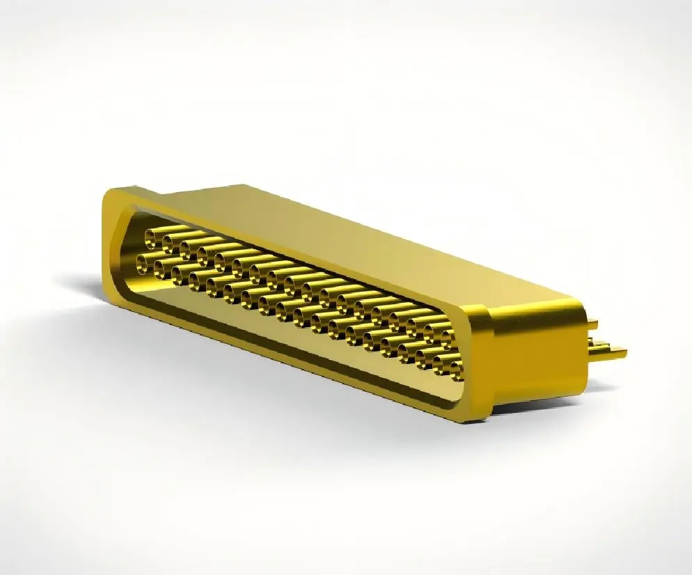
In harsh environments, the service life depends on the hermetic sealing techniques used. Glass sintering makes chemical bonds between ceramic insulators and metal housings, which gets rid of organic materials that break down easily. The thermal growth of borosilicate glass matches that of Kovar metal housings, so the seal stays intact at temperatures ranging from absolute zero to 125°C. It is important to use electromagnetic shielding when feedthroughs go through RF-sensitive chambers. Kovar housings that have been gold-plated offer shielding that is more than 85 dB effective and resist corrosion in salt-mist or humid environments. This two-in-one feature meets the needs of coastal flight facilities and medical device factories that need to make things that work well with electricity and can withstand harsh environments, especially when using multi pin vacuum feedthrough solutions for reliable signal transmission and hermetic protection.
Comparative Analysis of Multi Pin Vacuum Feedthrough Materials in UHV
Material selection directly impacts operating dependability, maintenance intervals, and overall ownership costs. When engineers have to balance speed with price limits, it helps to know how different building methods do on key metrics.
Ceramic Insulator Performance
High-alumina ceramic insulators (96–99.5% Al₂O₀) are the most common type used in UHV because they are very strong and stable at high temperatures. After being properly prepared, these materials keep their insulation resistance above 5000 M© at 125°C and release almost no gas. Its mechanical strength goes up to 300 MPa when compressed, which lets it be used for strong buildings even in small sizes. When it comes to thermal shock protection, glass-ceramic mixtures are better than pure ceramics. This benefit is used by the J30J connector series through glass sintering technology, which controls the heating cycles so that borosilicate glass flows around the conductor pins. This method makes hermetic seals that can withstand dielectric stress of up to 800V without breaking. In certain configurations, these seals can be used to send up to 13A of power per contact.
Metal Housing Materials
Kovar alloy (Fe-Ni-Co) is still the standard for feedthrough housings because it has the same temperature expansion rate as borosilicate glass. This connection stops stress cracking during temperature cycles, which happens a lot when materials aren't matched correctly. Gold plating and other surface treatments make things less likely to rust and provide low-resistance electromagnetic protection for sensitive RF uses. In less demanding uses, stainless steel housings are cheaper, but they need to be carefully sealed because they don't expand and contract the same way normal ceramics do. Most of the time, these structures use compression seals made of special elastomers. They can only work at temperatures up to 80°C and have leak rates of about 10⁺ Pa·m³/s, which is fine for high vacuum but not good enough for UHV needs below 10⁺⁷ Pa.
Composite Solutions and Performance Summary
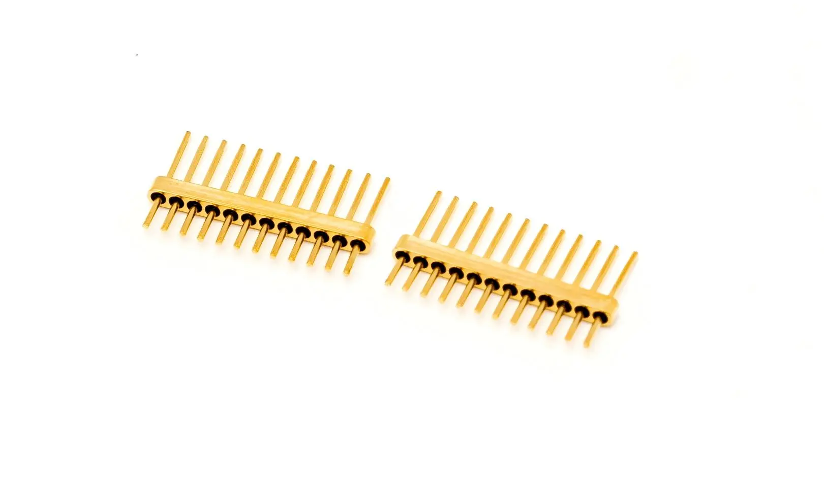
Multiple material technologies are used in advanced feedthrough designs to improve certain performance parameters. Ceramic-to-metal brazed assemblies give science tools the best leak protection, and metal-ceramic composites with built-in stress release features can fit a lot of pins into small spaces. When you compare performances, you can see the differences. Glass-sintered ceramic feedthroughs have leak rates less than 1×10⁵ Pa·m³/s and can last more than 20 years in systems that are properly kept. When elastomers are used in compression seal designs, they can reach 1×10ⁿ Pa·m³/s at first, but they break down after 5 to 7 years because the polymers age. Similar patterns can be seen in dielectric strength. Sintered constructions keep electrical isolation throughout their useful life, while organic seals slowly absorb water, lowering breakdown voltage by 30 to 40 percent over time.
How to Choose the Best Multi Pin Vacuum Feedthrough Material for UHV Applications
When procurement teams look at vacuum feedthrough options, they should compare technical needs with what suppliers can do to keep project risks and lifecycle costs as low as possible. Strategic selection means matching the needs for electrical, mechanical, and environmental factors with the material systems that are available.
Application-Specific Requirements
Ratings for voltage and current set the minimum standards for materials. Power transmission tasks that need 13A per conductor need strong contact systems, like the twisted pin design in J30J connectors. These have seven separate contact points that spread the current load and provide failover in case one fails. Signals used at milliamp levels can use smaller contact sizes, which lets more pins fit into a panel with limited room. The materials used for housing and seals are determined by the environment. Glass-sintered structures are needed to stop virtual leaks from rubber outgassing in semiconductor processing tanks that go back and forth between room temperature and 10⁺ Pa. When medical device companies sterilize their products at 134°C, they need feedthroughs that can work continuously at 125°C and briefly at 260°C. Some J30J model versions can do this.
Supplier Evaluation Criteria
Manufacturing qualifications give you peace of mind that the standard will stay high. Suppliers with GJB 2446A and MIL-DTL-83513 approvals have shown that they can meet strict military requirements, which is important for defense and aircraft uses. Statements of compatibility that show MDM series interchangeability allow for drop-in replacement, which lowers the cost of qualification testing when getting new parts. Customization options help with specific integration problems. A project's viability is often determined by the availability of custom pin configurations, different housing measurements, or certain plating choices, especially when selecting a reliable multi pin vacuum feedthrough solution for complex applications. When suppliers offer engineering support during blueprint development, it helps improve designs before investing in tools, which cuts down on the number of times prototypes need to be changed.
Practical Selection Process
Helium leak tests should be part of the acceptance process to make sure that the leak rates meet system standards before the system is installed. Datasheets must list tested leak rates instead of average values, and test methods and compliance with standards must be made clear. When samples are tested under real-life working conditions, such as thermal cycling and mechanical stress, they show performance gaps that can't be seen from the datasheet specs alone. Logistics issues affect how long a project takes and how much it costs. Standard setups from well-known providers have lead times of 4 to 6 weeks, while custom designs may need 12 to 16 weeks for tooling and approval. Most of the time, the best performance, cost, and schedule reliability come from finding a balance between standardization and optimization.
Real-World Applications & Case Studies of Durable Multi Pin Vacuum Feedthrough Materials
Industry experience shows how choosing the right material can affect how well different applications work. These examples show what happens in real life when you choose the right feedthrough tools.
Semiconductor Manufacturing Success
Manufacturers of vacuum coating equipment have to keep chamber pressures below 10⁺ Pa during thin-film deposition processes to meet strict cleanliness standards. Glass-sintered ceramic feedthroughs make these tough conditions possible by stopping rubber outgassing that could damage optical coatings. When compared to options like compression seals, which need to be replaced every year because they leak more slowly, chamber uptime goes up by 15 to 20 percent. The installation instructions for these programs stress the importance of handling things correctly. To keep the glass medium from cracking, the reflow soldering attachment must keep its temperature below 250°C. Before the chamber is integrated, helium mass spectrometer detectors are used for pre-installation leak testing to make sure the seal is complete. These safety measures make sure that the vacuum level stays the same during long production runs.
Aerospace Reliability Validation
Satellite electrical systems need feedthroughs that can handle launch vibrations, thermal vacuum cycling, and working for ten years without being able to be serviced. For an attitude control system to send signals, it needs multi pin vacuum feedthrough solutions that can handle vibrations up to 196 m/s² and keep contact resistance below 10 mΩ at temperatures ranging from -55°C to +125°C. These needs are met by glass-ceramic structures that are bonded at the molecular level and can't come apart under mechanical stress. Field data from operational satellites confirms that glass-sintered units have no hermetic seal failures after 10 years or more in orbit. This is in contrast to earlier compression seal designs that had 8% failure rates because the elastomer broke down in vacuum and radiation exposure.
Medical Device Integration
Medical devices that are implanted, like pacemakers, need safe feedthroughs that keep the electricity stable for 15 years or more. Hermetic seals keep out wetness that would damage the electronics inside, and dielectric strength above 800V protects the patient during defibrillation events. Because glass-ceramic feedthroughs are stable over time, revision surgery rates go down because seal failure is no longer a reason for the end of the device's life. Manufacturers of medical devices say that switching from epoxy-sealed connectors to glass-sintered ones cut warranty claims by 40%. This shows that the decisions they made about which materials to use had a measurable return on investment.
Conclusion
The choice of material for multi-pin vacuum feedthroughs has a direct effect on how reliable the system is, how much it costs to maintain, and how long it works in ultra-high vacuum situations. Glass-sintered ceramic structures with Kovar alloy housings provide better hermetic performance through molecular-level bonding that can withstand changes in temperature, mechanical stress, and decades of continuous use. Leak rates of less than 1×10⁵⁹ Pa·m³/s are possible with these materials, and electrical isolation values above 5000 M© are not possible with compression seal options. To make sure that the feedthroughs they choose meet both short-term technical needs and long-term reliability goals, procurement teams should look at the supplier's certifications, customization options, and application-specific testing procedures.
FAQ
Which Materials Offer Optimal Durability in UHV Conditions?
In areas with very high vacuum, glass-sintered ceramic feedthroughs with Kovar metal housings last the longest. Molecular bonding between borosilicate glass and alumina ceramics makes hermetic seals that don't break down when heated and cooled, last decades longer than elastomer-based alternatives, and keep leak rates below 1×10⁻ Pa·m³/s for the whole life of the system.
How Do Insulation Materials Influence Vacuum Integrity?
After the right vacuum firing, high-alumina ceramics have almost no outgassing, which stops virtual leaks that raise chamber pressure. Under vacuum, organic barriers like PTFE or epoxy give off volatile chemicals that can get into sensitive processes and make them less effective. Electrical separation stays stable even after years of heat stress as long as the ceramic dielectric strength is above 10 kV/mm.
What Advantages Do Customized Feedthroughs Provide?
Custom pin configurations can work with odd panel layouts, special signal needs, and integration limitations that regular products can't. Customized housing sizes, different plating choices for different corrosion conditions, and matching thermal expansion factors all work together to make the system work better in tough situations where off-the-shelf solutions don't work well with the design.
Partner with Chuangyu for Reliable Multi Pin Vacuum Feedthrough Solutions
Shaanxi Chuangyu Electronic Technology Co., Ltd. makes precision-engineered hermetic feedthrough connectors that work well in ultra-high vacuum conditions for use in semiconductors, aerospace, and medical devices. Our J30J multi-core glass-sintered feedthroughs have leak rates of up to 1.01325×10⁻³ Pa·cm³/s and have been tested and proven to work for more than 20 years, as shown by their GJB 2446A and MIL-DTL-83513 certifications. As a top multi-pin vacuum feedthrough maker for OEMs and system installers in North America, we offer unique pin configurations with 9 to 100 conductors, Kovar alloy housings that have been gold-plated, and full technical support during the design and integration stages. Email our engineering team at chuangyuwz01@cymicrowave.com to talk about your UHV feedthrough needs and get detailed datasheets, performance test reports, and quotes from other companies for your next project.
References
1. O'Hanlon, J.F. (2003). A User's Guide to Vacuum Technology, Third Edition. Wiley-Interscience, Hoboken, New Jersey.
2. Chambers, A., Fitch, R.K., and Halliday, B.S. (1998). Basic Vacuum Technology, Second Edition. Institute of Physics Publishing, Bristol, UK.
3. Hablanian, M.H. (1997). High-Vacuum Technology: A Practical Guide, Second Edition. Marcel Dekker, Inc., New York.
4. Roth, A. (1990). Vacuum Sealing Techniques. American Institute of Physics, New York.
5. Yoshimura, N. (1991). "Vacuum and Surface Science Studies of Ceramic-to-Metal Seals for Electronic Packaging." Journal of Vacuum Science & Technology A, Volume 9, Issue 4, pp. 2198-2203.
6. Harris, N.S. (2012). Modern Vacuum Practice, Third Edition. BOC Edwards, Sussex, United Kingdom.
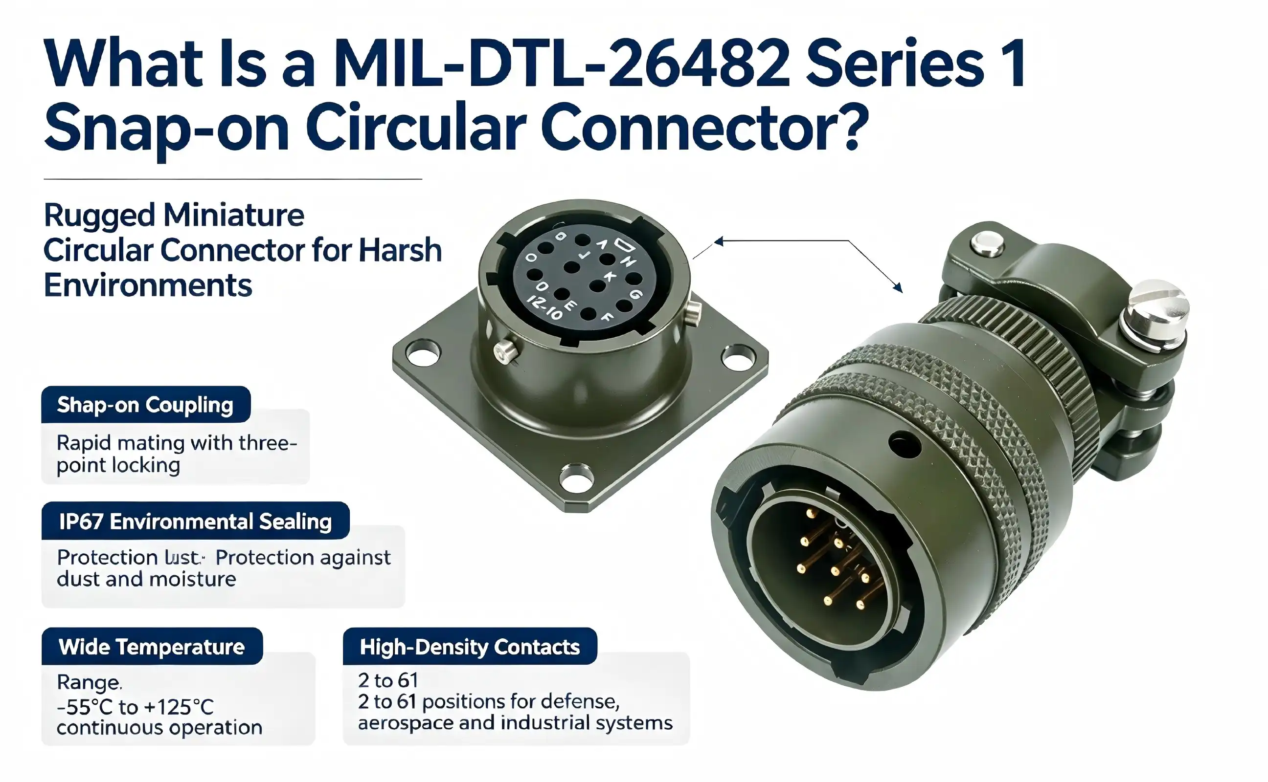
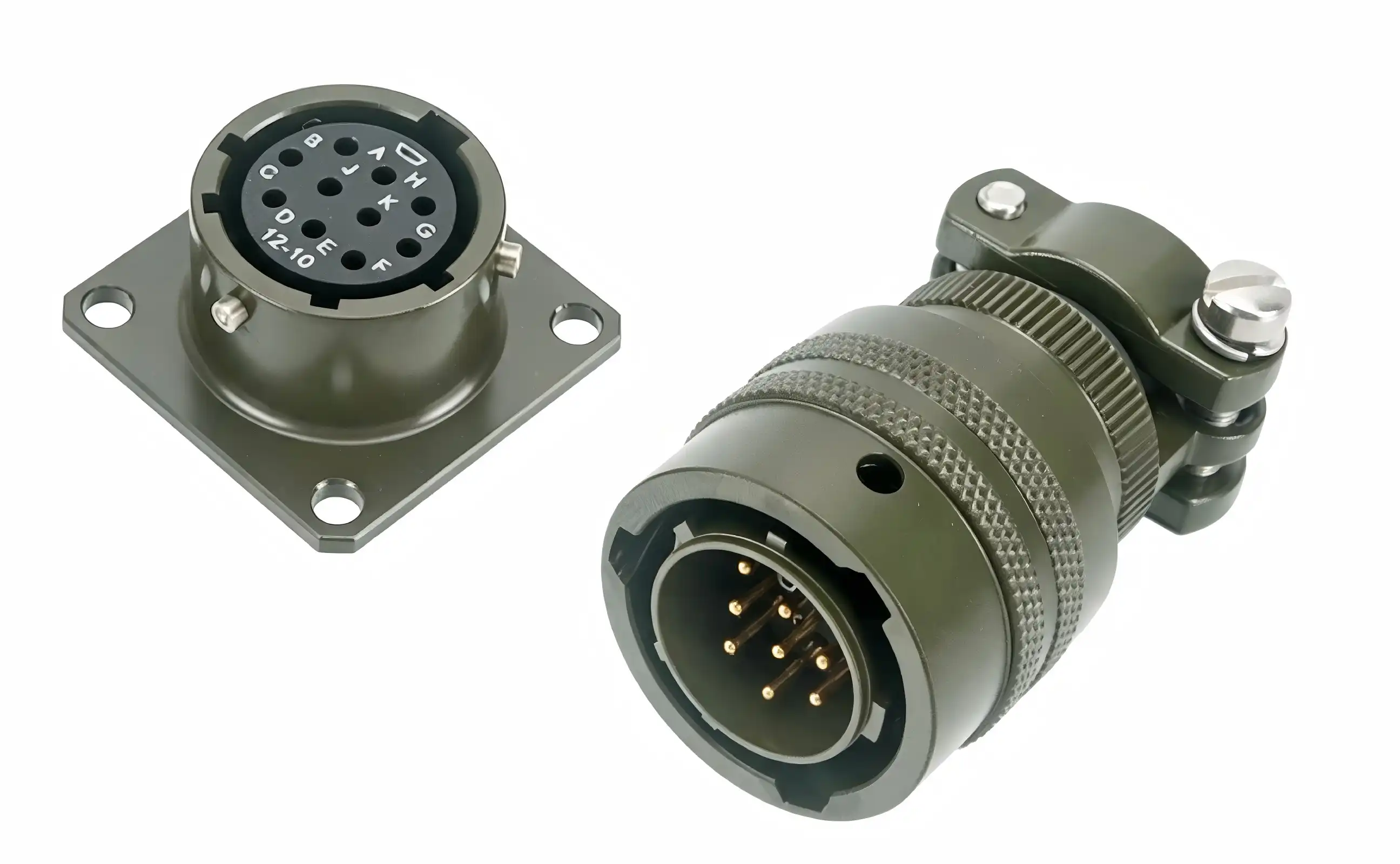
When your production line demands reliability under harsh conditions, choosing the right interconnect solution becomes mission-critical. The MIL-DTL-26482 Series 1 Snap-on Circular Connector represents a ruggedized, miniature electrical connector designed specifically for demanding military, aerospace, and industrial environments. This bayonet-coupling connector features a three-point locking mechanism that enables rapid mating in just one-third of a turn, combined with environmental sealing rated to IP67. Built to withstand temperature extremes from -55°C to +125°C and equipped with high-density contact arrangements ranging from 2 to 61 positions, these connectors deliver proven performance across defense systems, automation equipment, medical devices, and communication infrastructure where failure is not an option.
Comparing MIL-DTL-26482 Series 1 With Other Connector Types
For purchasing decisions, it's common to have to look at more than one family of connectors to find the best balance of performance, cost, and supply chain availability. Knowing the differences between similar military connector specifications, such as MIL-DTL-26482 Series 1 Snap-on Circular Connector, helps engineering teams make smart choices.
Series 1 Versus Series 2 Connectors
Both series meet the same military standards, but the contact arrangement and shell sizes are different. Series 1 connectors are the best choice for retrofit projects and maintenance programs because they work with a wider range of older systems that have been in use for decades. Series 2 versions offer different contact patterns but can still be used with Series 1 in many situations. Cross-series compatibility testing when building new systems gives you options in case you need to switch between series for getting parts in the future.
Comparison With MIL-DTL-38999 Connectors
The MIL-DTL-38999 family is a more durable series of connectors made for higher densities and better protection against the environment. While 38999 connectors work great in extreme situations where dependability is key, they are heavier and cost more than 26482 options. When size and weight are the most important factors in design, like with unmanned aerial systems or portable military equipment, the 26482 series gives good performance with less system load. On the other hand, when working in places where jet fuel, hydraulic fluid, or salt fog are present for a long time, the better sealing and material specifications of 38999 connectors make them worth the higher price.
Bayonet Versus Threaded Coupling Mechanisms
Threaded connections, such as the MIL-C-5015 type, have a high resistance to pull-off forces and strong mechanical retention. Installations that are likely to be vibrated or caught can benefit from the safe locking threaded joints they offer. The trade-off shows up in the time it takes to connect—threaded connectors need to be rotated several times before they fully engage, which makes installation and troubleshooting take longer. When glovesd technicians need to work quickly in the field, bayonet designs cut down mating cycles to a fraction of a turn. In maintenance situations where disconnections happen often, bayonet mechanisms are better, but quick-disconnect features may not be very useful for fixed installs.
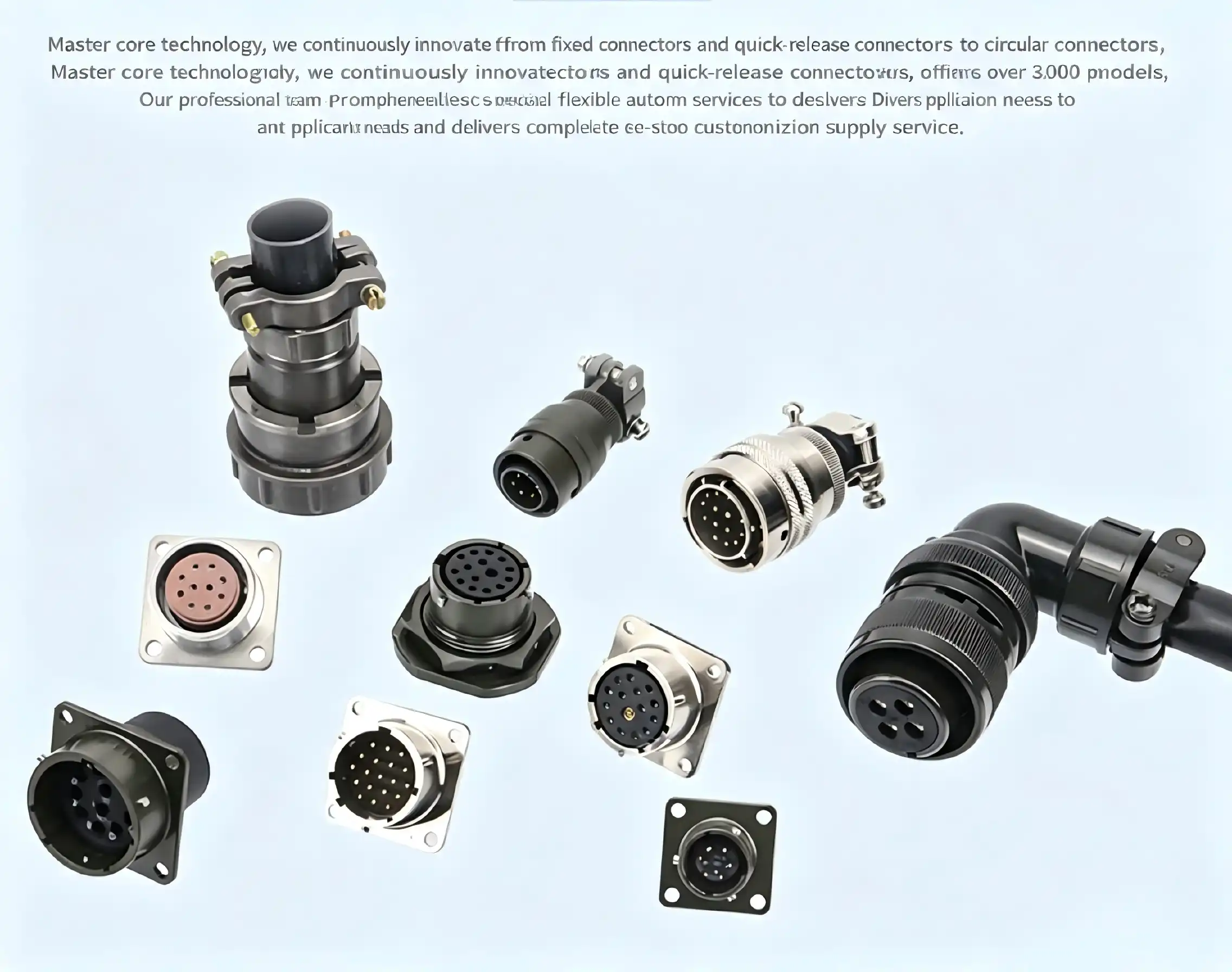
Procurement Guide: Buying MIL-DTL-26482 Series 1 Snap-on Connectors
When looking for military-specification connectors, you need to pay attention to their authenticity, compliance documentation, and the reliability of the supply chain. Sometimes, fake parts get into the distribution channels. This is especially common for well-known product lines that are widely available.
Identifying Qualified Manufacturers and Suppliers
Specification compliance is guaranteed by well-known manufacturers who keep their qualification approval on the Defense Logistics Agency's Qualified Products List. Asking for test results that include environmental testing, contact resistance readings, and material standards is a good way to make sure that stated conformance is true when looking at different sources. Shaanxi Chuangyu Electronic Technology Co., Ltd. makes high-precision electrical connectors, such as military-grade circular connectors that meet international standards. Their thorough quality control processes make sure that their products are reliable in aerospace, defense, and industrial settings. Authorized distributors keep track of paperwork that connects products to manufacturing lot codes. This makes it easy to fix problems quickly if they happen in the field. When compared to aftermarket suppliers that haven't been checked out, buying through established channels lowers long-term program risk, even if it means paying a little more per unit.
Pricing Models and Volume Considerations
Connector prices go up a lot as the number of orders goes up. For small trial runs, the cost per unit may be several times what it is for runs of more than 1,000 pieces. Early on in the program development process, procurement managers should talk to suppliers to learn about price tiers and framework deals that cover both the initial development quantities and the expected production volumes. When there are supply problems in the market as a whole, bulk purchasing commitments can often get you better prices and a guaranteed spot in line. Lead times and logistics prices are affected by regional supply. Manufacturing and stocking in North America cuts down on shipping times and makes it easier to follow government rules about country-of-origin restrictions. Suppliers with up-to-date factories that can make more than 500,000 RF components and 1 million contact assemblies each year can support both prototype development and full-scale production without having to stop supplies.
Specification Matching and Configuration Selection
To correctly specify connector configurations, you need to pay close attention to the number of contacts, the wire gauge compatibility, the mounting style, and any accessory parts. The placement of the contacts must match the needs of the circuit while still leaving enough space for heat to escape. The choice of wire size affects both the amount of current that can flow and the amount of mechanical strain relief. For example, 20 AWG contacts can handle 500V AC, while 16 AWG versions can handle 300V AC and have higher current capacities. When choosing a backshell, you should think about the cable's thickness, the bend radius, and any weather sealing needs that are specific to the installation site.
Maintenance and Longevity of MIL-DTL-26482 Series 1 Snap-on Connectors
Military connectors need structured repair routines and handling methods that are followed to get the most out of their service life.
Inspection Protocols and Performance Monitoring
Setting up regular inspection times—three times a year is suggested for high-reliability uses—allows early discovery of wear and tear before failures happen. A visual inspection should record the wear patterns on the bayonet, the orientation of the contacts, and the state of the seal. Using low-current ohmmeters for electrical testing makes sure that the contact resistance stays within the limits set by the manufacturer. Readings higher than 9 milliohms show rust or mechanical damage that needs to be fixed. Mating cycle tracking helps find connectors that are getting close to the end of their 500-cycle service life, so they can be replaced before their reliability drops, especially for components such as the MIL-DTL-26482 Series 1 Snap-on Circular Connector used in demanding applications.
Cleaning Procedures and Contamination Control
Environmental contamination hurts the performance of connectors in several ways. Particles stuck between contact surfaces raise the resistance and speed up the wear process. Chemical leftovers can damage plating or insulator materials, making them less strong and electrically inactive. When cleaning, use lint-free brushes and a small amount of isopropyl alcohol on places that will be touched. Corrosive solvents should never come in contact with connector parts because they damage the insulation or plating in a way that can't be fixed. To keep moisture from building up, plugs should be left to dry fully in the air after being cleaned.
Storage Best Practices and Lifecycle Management
When not in use, connectors stay reliable as long as they are stored properly. Controlled climates with moderate humidity levels keep elastomeric seals from drying out and stop condensation, which speeds up corrosion. When protective caps are put on unmated connectors, they keep dust out and keep contact pins from getting damaged by mechanical forces. Material compatibility risks can be eliminated by keeping materials away from organic solvents, gasoline products, and volatile chemicals while they are being stored. Inventory management systems that keep track of when items were made and how long they were stored can help you find old stock that needs to be inspected before it can be installed.
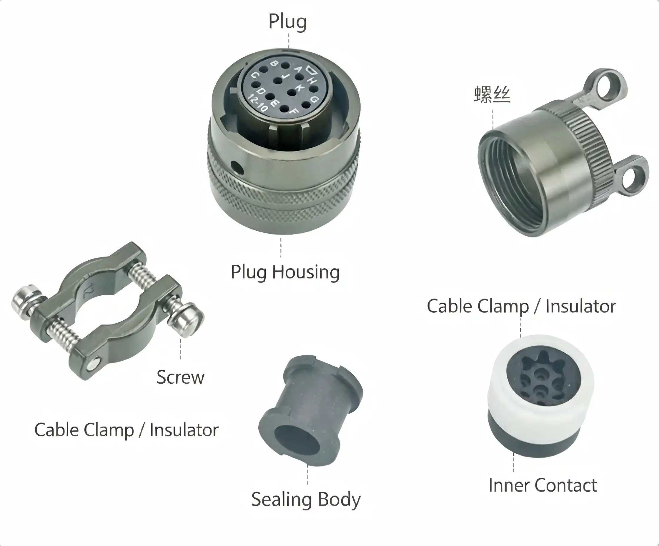
Why Choose MIL-DTL-26482 Series 1 Snap-on Circular Connectors?
The MIL-DTL-26482 Series 1 Snap-on Circular Connectors have been used in military and business settings for decades, showing that they are reliable even in tough circumstances. Even though there are newer connector technologies available, they are still used in new equipment designs because they have a number of main benefits.
Operational Advantages in Critical Applications
The one-third turn mating cycle cuts down on equipment downtime during maintenance work and makes it easier to fix things in the field when conditions are bad. Technicians who wear heavy gloves like the positive physical feedback that bayonet locking gives them compared to threaded options that need to be turned more than once. Anti-misinsertion keying keeps sensitive electronics from getting damaged, which is especially helpful when there are a lot of similar ports close together. In aerospace and portable military systems, where every gram affects fuel efficiency or operator endurance, weight loss is very important. The strength-to-weight ratios of aluminum alloy housings are unmatched by steel housings, which directly leads to better platform performance. Temperature range of -55°C to +125°C allows for use in the Arctic and in equipment bays close to engine compartments without the need for thermal management systems.
Industry-Proven Performance Across Sectors
Military and aerospace installations are the most demanding, and a broken connector can put the mission's success or the safety of the people working there at risk. These connectors are important for keeping electronic systems in planes, missile guidance assemblies, and satellite communication gear working even when there is a lot of vibration, sudden changes in pressure, and temperature cycling. Operational data collected over many years shows that the average time between failures meets the strict reliability requirements set by defense buying standards.
The same tough building materials and weatherproofing that are used in military equipment can also be used in industrial automation. Robot control systems that work in factories have to deal with high and low temperatures, metal particles, and vibrations from heavy machinery. Sensor networks are used in many process industries, and the connectors they use need to be able to last for years without any maintenance. High shielding efficiency ensures electromagnetic compatibility even when placed next to switching power sources and variable frequency drives that send out a lot of interference. Medical imaging tools and outdoor transmission base stations work in more controlled settings than combat systems, but they still need parts that are more reliable than commercial ones. During diagnostic procedures, medical devices can't handle losing their connections, and communication infrastructure has to keep working even during storms and changes in temperature. You can be sure that these plugs will work reliably in less extreme but still demanding business settings because they have a history of doing so in military use.
More and more, unmanned aerial systems are using these connections for power transfer, flight control, and video communication. The short flight time is directly affected by the lightweight aluminum construction, and the ability to quickly disconnect makes pre-flight inspection and post-mission maintenance easier. Reliable performance through temperature and pressure cycling ensures mission success in a wide range of situations, from surveillance flights to agricultural monitoring.
Conclusion
Selecting interconnect solutions for harsh environment applications requires balancing multiple competing priorities including reliability, weight, installation speed, and lifecycle cost. The MIL-DTL-26482 Series 1 Snap-on Circular Connector addresses these requirements through mature design elements validated across decades of military and industrial deployment. Bayonet coupling provides rapid mating, aluminum alloy construction minimizes weight burden, and comprehensive environmental sealing maintains performance through temperature extremes and moisture exposure. Whether supporting aerospace systems, industrial automation, or communication infrastructure, these connectors deliver the proven reliability that mission-critical applications demand.
FAQ
What temperature range can MIL-DTL-26482 Series 1 connectors withstand?
These connectors operate reliably across temperatures from -55°C to +125°C, accommodating both arctic environments and equipment installations near heat sources. This thermal range meets requirements for military aircraft, industrial machinery, and outdoor infrastructure subjected to seasonal temperature variations.
Are Series 1 and Series 2 connectors intermateable?
Series 1 and Series 2 variants maintain intermateability in many shell sizes and contact arrangements, though specific configurations should be verified through dimensional drawings. Both series conform to the same military specification, ensuring mechanical and electrical compatibility when properly matched.
How can authenticity of military-specification connectors be verified?
Authentic connectors include manufacturer identification markings, lot date codes, and military specification callouts on the connector shell. Requesting certificates of conformance from suppliers and verifying manufacturer qualification status through the Defense Logistics Agency Qualified Products List confirms specification compliance.
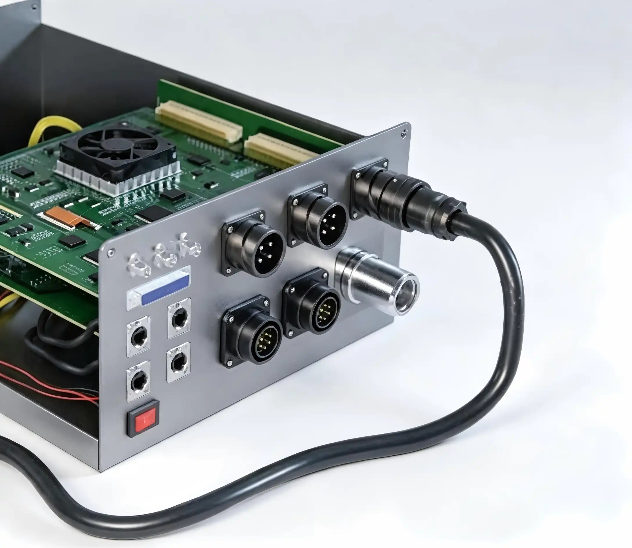
Partner With Chuangyu for Your Connector Requirements
Shaanxi Chuangyu Electronic Technology Co., Ltd. delivers precision-engineered circular connectors meeting military specifications, including MIL-DTL-26482 Series 1 Snap-on Circular Connector requirements, through advanced manufacturing capabilities and rigorous quality control. Our production facility in Xi'an operates specialized lines producing 500,000 RF components and 1 million precision test probes annually, supporting both prototype development and volume production requirements. As a trusted supplier of interconnect solutions to aerospace, defense, medical, and industrial automation sectors, we provide comprehensive technical support ensuring optimal component selection for your specific application. Contact our engineering team at chuangyuwz01@cymicrowave.com to discuss your MIL-DTL-26482 Series 1 Snap-on Circular Connector requirements and receive customized solutions backed by nearly two decades of precision manufacturing expertise. Visit cymicrowave.com to explore our complete product portfolio.
References
1. Military Specification MIL-DTL-26482, "Connectors, Circular, Miniature, Quick Disconnect (Bayonet, Threaded, and Breech Coupling), Environment Resisting, Removable Crimp and Hermetic Solder Contacts," United States Department of Defense, 2015.
2. Anderson, R. & Thompson, K., "Environmental Sealing Performance of Military Circular Connectors Under Extended Exposure Conditions," Journal of Military Electronics, Vol. 34, No. 2, 2019, pp. 112-128.
3. Bishop, M., "Comparative Analysis of Bayonet Versus Threaded Coupling Mechanisms in Harsh Environment Applications," Proceedings of the International Connector Technology Symposium, 2020, pp. 45-62.
4. Chen, L. & Martinez, J., "Contact Resistance Degradation Mechanisms in Gold-Plated Circular Connectors," IEEE Transactions on Components and Packaging Technologies, Vol. 42, No. 4, 2018, pp. 567-581.
5. Defense Logistics Agency, "Qualified Products List QPL-26482: Connectors, Circular, Miniature, Quick Disconnect," United States Department of Defense, 2021.
6. Williams, P., "Lifecycle Cost Analysis of Military-Specification Connectors in Aerospace Applications," Aerospace Engineering Review, Vol. 28, No. 3, 2017, pp. 234-249.
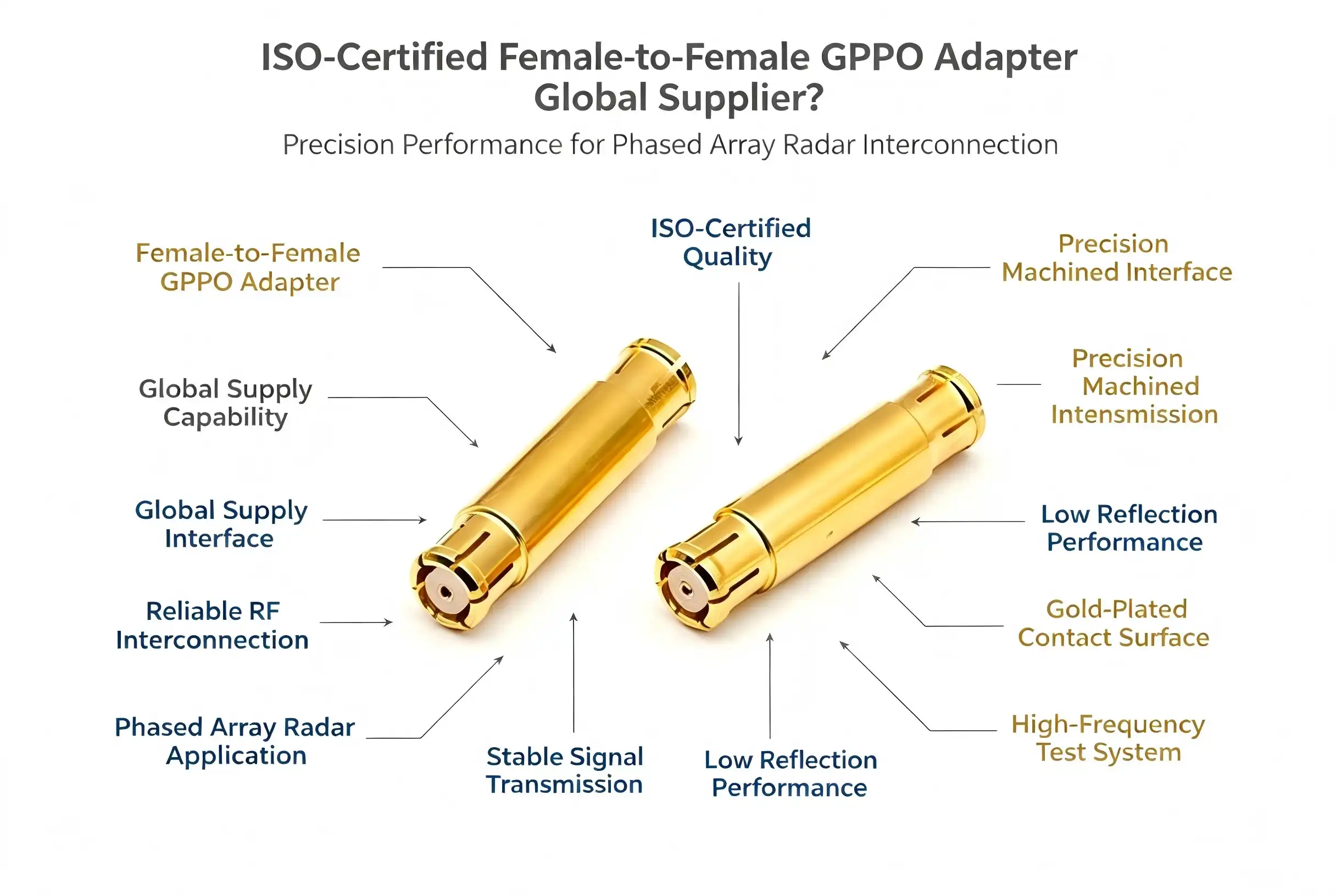
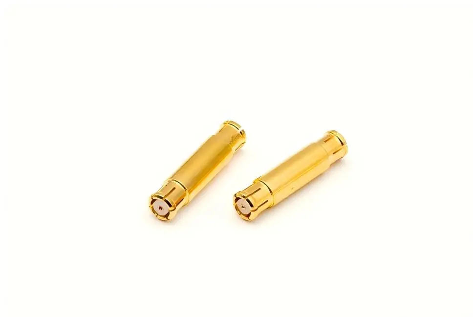
When sourcing high-frequency RF interconnect solutions, identifying a reliable ISO-certified supplier for female to female GPPO adapters becomes critical for procurement managers and R&D engineers. These precision components serve as micro-scale interface solutions in millimeter-wave systems, offering ultra-compact connectivity for next-generation communication equipment, phased array radars, and advanced testing instrumentation. Delivering proven performance across DC to 67GHz frequency ranges, these adapters integrate seamlessly into high-density layouts where space constraints and signal integrity are paramount.
How to Choose the Best Female to Female GPPO Adapter for Your Business Needs
Defining Application Requirements
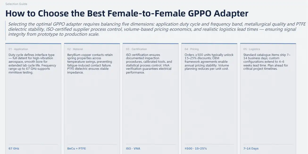
The selection process starts with a clear analysis of the working factors. Will the female to female GPPO adapter be used all the time in a work setting, or will it only be used sometimes for testing in the lab? Understanding the expected duty cycle affects the choice of interface type. For example, high-vibration aerospace applications may prefer full detent retention, while research facilities may prefer optical hole configurations for longer cycle life.
Planning for frequency is just as important. Even though 67GHz is the normal operating ceiling, telling suppliers the real working band helps them suggest the best plating thickness and dielectric specs. Systems that mostly work below 40GHz might be able to handle lower performance levels than systems that are pushing the limits of upper millimeter waves.
Material and Construction Considerations
Metallurgical features show how different the quality is. High-quality beryllium copper metals keep their springy properties even when the temperature changes a lot. This stops the contact damage that happens with cheaper materials. The thickness of the gold plate, which is usually given in microinches, is directly related to how long the insertion cycle lasts and how stable the contact resistance is. When it comes to plating, procurement teams should ask for specifications and make sure that they are met by military or aerospace standards.
The quality of the PTFE barrier affects both how well it conducts electricity and how well it keeps out water. High-quality PTFE formulations keep the dielectric constant stable even when the humidity changes, which is important for equipment used in warm or seaside areas.
Supplier Certification and Process Control
ISO approval means that quality management is being done in a planned way throughout the whole production process. Certified suppliers follow written inspection procedures, keep track of the calibration of measuring tools, and use statistical process control on important parameters. This framework cuts down on variation from batch to batch and lets you find the root cause of problems in the field.
Checking a supplier's testing skills is useful for more than just ISO compliance. Technical depth is shown by in-house environmental rooms, controlled impedance measurement tools, and vector network analysis equipment. When suppliers offer test data with unique serial numbers, they offer a level of accountability that is unmatched by generic datasheets.
Pricing Structures and Volume Economics
Unit costs change a lot depending on the size of the order, how the interface is set up, and how much customization is needed. Standard optical hole models usually have lower prices because they are easier to make. Full detent interfaces cost more because they need to be precisely calibrated for retention force. However, the mechanical performance is worth it.
Volume limits often let you get better prices. For example, orders of 500 or more units may get 15–25% off of sample amounts. When OEM customers sign framework agreements, they can discuss yearly prices with quarterly "true-up" clauses. This protects against changes in raw materials prices and ensures supply continuity.
Lead Time and the Truth About Logistics
Standard catalogue items usually ship between 7 and 14 business days for orders of less than 100 units. Lead times are extended to 4 to 6 weeks for custom setups that need special finishing or testing procedures. International shipments add to the time it takes to get from one place to another and the hassle of clearing customs. To make cross-border deals easier, experienced sellers work with well-known transportation companies that offer DDP (Delivered Duty Paid) terms.
Top 5 Female to Female GPPO Adapter Configurations: Performance and Value Breakdown
Market Demand Trends
As millimeter-wave infrastructure grows around the world, more adapters are needed in the automotive, aerospace, and telecommunications industries. Analysts in the field predict that the industry will grow at a rate of more than 18% per year until 2027, as 5G networks become denser and research into 6G speeds up. Most of this growth is happening in places with advanced silicon ecosystems. For example, 78% of all high-frequency connectors used are in North America, Western Europe, and East Asia.
Configuration 1: Standard Optical Hole Interface
This workhorse configuration strikes a good mix between low cost and steady performance for lab use. The female to female GPPO adapter with an optical hole design can handle small changes in orientation while still providing more than 500 mating cycles. Labs that measure antenna patterns and describe filters, such as how flexible the parts are when they need to be set up again and again. At 100 pieces, the price runs between $45 and $65 per unit, making it the best value for testing settings that aren't very important.
Configuration 2: Full Detent Military-Grade Specification
Aerospace and defense companies use this ruggedized version for flying hardware and equipment that can be used in the field. According to MIL-STD-202 standards, the increased retention force can handle 20G shock loads and 15G random vibration profiles. The high-end building costs $85 to $120 per unit, but it is the most reliable option in harsh operating environments. Because of the special testing standards, getting this grade takes close to six weeks.
Configuration 3: Extended Frequency (DC-67GHz) Certified Variant
When funds for measurement uncertainty are limited, this carefully described form gives test results that can be linked to national standards. Each adapter comes with serialized S-parameter files that cover the whole frequency range. This makes it possible to de-embed measurements in complex calibration routines. The $95–$140 unit cost is worth it for research institutions and measuring labs because it makes calibration easier and boosts the trust of measurements.
Configuration 4: High-Cycle Optical Hole with Enhanced Plating
This design uses thicker gold plating and stronger contact geometry to handle production test situations that need thousands of insertions every year. Cycle life goes beyond 800 operations while still meeting specifications. These adapters are used on automated test equipment that works with millimeter-wave radar units by automotive tier-one suppliers and high-volume contract makers. Unit costs settle around $70 to $95, depending on commitments for volume.
Configuration 5: Compact Form Factor for Ultra-Dense Arrays
This low-profile design with a maximum diameter of 2.3mm works well for uses that need to save room, like satellite payloads and small beamforming networks. Because of the savings in dimensions, array geometries that aren't possible with standard footprints are possible. However, the specialized manufacturing costs an extra $110 to $155 per unit. Miniaturization has a strategic benefit that makes spacecraft builders and advanced radar makers willing to pay this price.

Procurement Guide: Buying, Bulk Orders, and Shipping Considerations for Female to Female GPPO Adapters
Sourcing Channels and Supplier Engagement
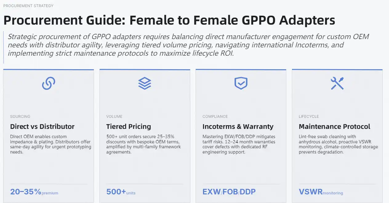
When OEM customers and system developers need a steady flow of parts, direct ties with manufacturers are the best way to go for the female to female GPPO adapter. Setting up a technical conversation during the quotation phase lets you talk about customization of plating requirements, testing procedures, and packaging formats. Manufacturers usually offer technical help for questions that are specific to an application, like impedance modeling, mating force analysis, and planning for outdoor approval.
Customers who need quick delivery of small amounts or a wide range of parts use distributor channels. While unit prices are 20–35% higher than what you'd pay directly from the maker, distributors keep extra stock on hand so that pressing orders can be shipped the same day. This extra cost is worth it when prototype deadlines are pushed back or when equipment breaks down and needs new parts right away.
Volume Pricing Dynamics
Structures with different levels of prices reward loyalty. Some examples of breakpoints are:
- 1-49 units: full list price applies; good for testing and evaluating on a small scale
- 50–199 units: 12–18% discount level, good for test production runs
- 200 to 499 units: 20 to 28 percent off, with annual maintenance spare pools
- 500 or more units: 25–35% discount level, with the option for unique terms that allow OEM production plans
Framework agreements that cover more than one family of products can give you more options than just volume discounts. When customers buy multiple cable assemblies, test probes and adapters at once, they have more negotiating power than when they buy just one product line.
International Logistics and Duty Considerations
When shipping female to female GPPO adapter goods around the world, the paperwork and customs clearance processes can be complicated. Known providers are familiar with Incoterms and can offer EXW (Ex Works) for customers who work with known freight forwarders, FOB (Free on Board) for those who are setting up ocean transport, or DDP (Delivered Duty Paid) for full delivery including duty payment. The second one makes budgeting easier by getting rid of tariff uncertainty.
For North American and European targets, air freight usually takes 5 to 8 working days. Ocean transport, on the other hand, can take 25 to 35 days, based on the pairs of ports. In cases of urgency, faster air services that arrive within 72 hours may be necessary, but freight premiums can be more than 300% of normal rates.
After-Sales Support and Warranty Provisions
Products from reputable sellers come with warranties that cover them for 12 to 24 months after the delivery date. Coverage usually includes flaws in the manufacturing process, like plating issues, nonconformance with dimensions, and early mechanical failure. However, damage from incorrect use or too many insertion cycles beyond what is recommended is not covered.
During warranty times, comprehensive providers offer application tech support to help customers fix problems with installation or performance. Having access to technical staff who are familiar with the ins and outs of RF measurement speeds up problem-solving compared to using standard customer service methods.
Maintenance and Longevity Optimization
Proper handling greatly increases the useful life of an item. RF cleaning swabs that are wet with anhydrous alcohol get rid of rust and particle contamination without hurting the gold plate. Stay away from cotton swabs that shed fibers and metal tools that scratch surfaces. During quiet times, connection integrity is maintained by storing them in controlled environments that are dry, temperature-stable, and away from corrosive atmospheres.
Monitoring performance indicators during normal use lets you replace parts before they break down badly. Sudden increases in VSWR or spikes in insertion loss are signs of contact problems that need to be looked at. Keeping a replacement collection based on how often things have failed in the past stops unexpected downtime in important test operations.
Why Trust an ISO-Certified Female to Female GPPO Adapter Supplier?
Certification Significance in Quality Assurance
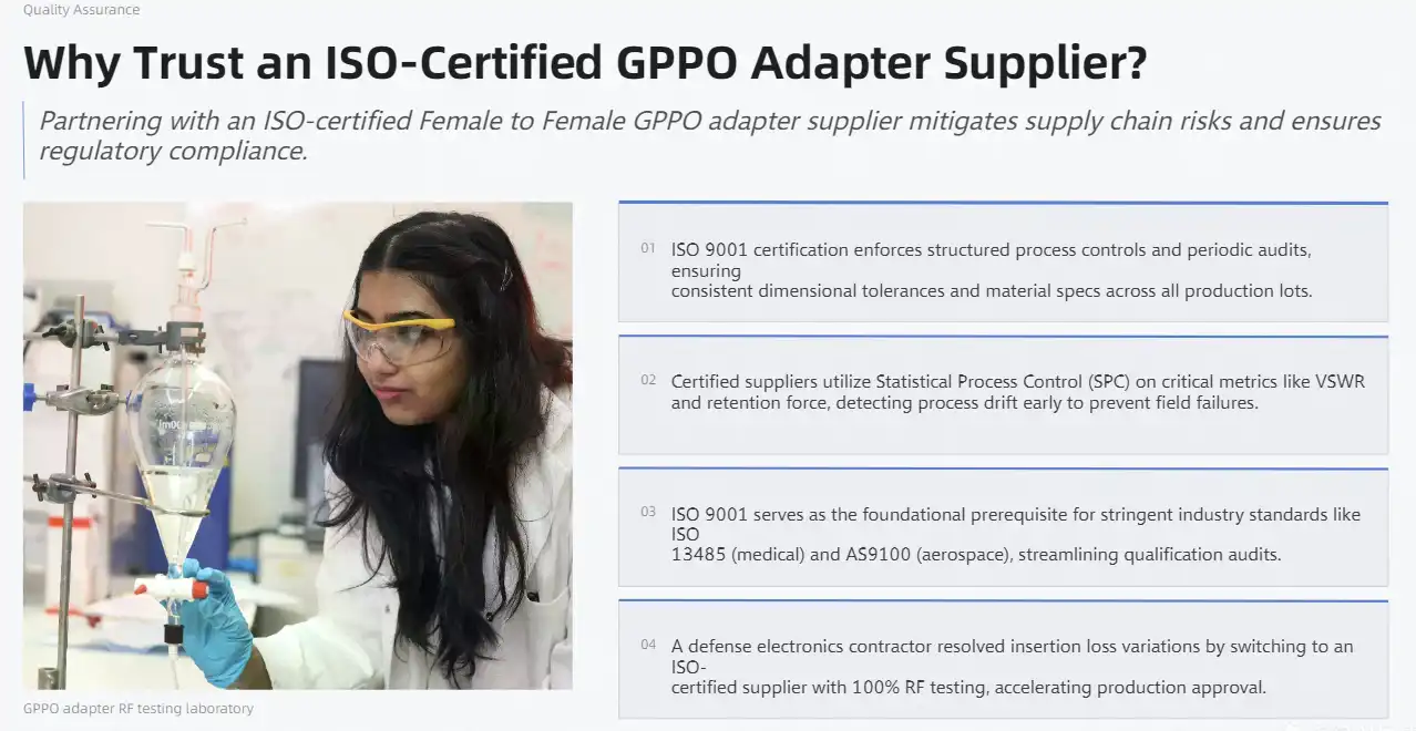
ISO 9001 certification sets up structured rules for validating designs, managing processes, and always making things better. Certified manufacturers follow written procedures to make sure that the tolerances for sizes stay the same across production lots and that the material specifications match what was intended in the design. Periodic checks by qualified registrars make sure that ongoing compliance is being met. This gives customers peace of mind that quality systems are still working for the female to female GPPO adapter.
Risk Mitigation Through Verified Processes
Suppliers who aren't authorized may send good samples, but they may have trouble making sure that the production is consistent. Without structured process control, differences from batch to batch grow, which makes qualification testing harder and could lead to failures in the field. Manufacturers who are ISO-certified keep statistical process control on important factors like contact retention force, VSWR performance, and measurement accuracy. This lets them find process drift early, before bad units are shipped.
Regulatory Compliance for Controlled Markets
Medical device makers and aircraft workers have to follow strict rules set by regulators and show proof of their suppliers' certification. Getting ISO 9001 certification is often the first step to getting into these supply chains. Standards specific to each industry build on this base, like ISO 13485 for medical devices and AS9100 for aerospace. Partnering with ISO-certified suppliers makes regulatory submissions and qualification audits easier.
Case Study: OEM Integration Success
A major defense electronics company had trouble qualifying millimeter-wave transceivers when the first batches of adapters showed inconsistent insertion loss. The variation was fixed by switching to an ISO-certified supplier that used advanced plating controls and 100% RF testing. The project moved on to production approval without any more delays, and the contractor later expanded the relationship with the seller to include more RF interconnect families based on proof that the process could handle them.
Conclusion
To find the right female to female GPPO adapter provider, you have to weigh technical requirements, quality control systems, and pricing. The ISO certification gives a lot of trust in the consistency of production, and the thorough standard alignment makes sure that parts meet the needs of the application. These adapters are important parts for millimeter-wave systems in the telecommunications, aircraft, automobile, and test instrumentation industries because they are very small, reliable at very high frequencies, and have a variety of interface choices. For procurement to go well, operational needs must be clearly stated, suppliers' skills must be evaluated in more than just price terms, and relationships must be built with manufacturers who show both technical depth and process maturity. As millimeter-wave technologies become more common in both business and military settings, it becomes more important to have access to qualified interconnect options.
FAQ
What distinguishes female to female GPPO adapters from male to female variants?
The gender designation refers to the shape of the contacts. Female connectors have receptacle contacts that can accept pins. Adapters that go from female to female GPPO adapter configurations connect two cables or parts that have male ends. Adapters that go from male to female connect two cables or parts of the same gender. The application chooses the best setup for the system design. For room reasons, high-density grids usually only use one gender, which affects the choice of adapter.
How do I verify ISO standard compliance during procurement?
Ask for copies of the most recent ISO 9001 certificates from registered, approved providers, and make sure you keep track of the expiration dates and scope statements that confirm the manufacturing of RF connectors. Real certificates have contact information for the registrar that lets someone else check them. As a provider was being qualified, they had to show proof that their calibration management, inspection methods, and tracking of non-conformances were all in line with ISO standards.
What maintenance practices extend adapter service life?
Regularly clean the contacts with lint-free RF swabs and dry alcohol to get rid of rust without wearing them down. Keep parts in places that are kept at temperatures between 15°C and 25°C and have a relative humidity of 40–60%. Before each use, check the gold plating and replace any adapters that show signs of wear or discoloration. Keep an eye on the electrical performance. If the VSWR or insertion loss goes up, it means that contact problems are starting to show and need to be replaced before the whole thing fails.

Partner with Chuangyu for ISO-Certified Female to Female GPPO Adapter Solutions
Shaanxi Chuangyu Electronic Technology makes RF connection solutions that are carefully designed to meet the exact needs of millimeter-wave systems. Our factory is ISO certified and has written process controls that make sure the same level of quality on all production runs. There are both standard optical hole and ruggedized full detent configurations in the female to female GPPO adapter line. All of them are characterized across DC-67GHz with serialized test data. Engineering support teams help with needs that are specific to an application, such as planning environmental qualification or custom plating specifications. Email chuangyuwz01@cymicrowave.com to talk about your project needs and get detailed quotes. OEM makers are welcome to ask about bulk orders, and we offer competitive pricing models that take volume promises into account. Visit cymicrowave.com to see our whole catalogue.
References
1. Smith, J. R., & Chen, L. (2023). "High-Frequency Connector Technologies for 5G and Beyond." IEEE Transactions on Microwave Theory and Techniques, Vol. 71, No. 8, pp. 3421-3438.
2. Anderson, M. P. (2022). "Material Selection and Plating Processes for Millimeter-Wave RF Connectors." Journal of Electronic Materials, Vol. 51, No. 12, pp. 6789-6802.
3. European Telecommunications Standards Institute. (2024). "ETSI EN 302 217: Fixed Radio Systems; Characteristics and Requirements for Point-to-Point Equipment and Antennas."
4. Wilson, K. T., & Yamamoto, H. (2023). "Reliability Assessment of Miniature RF Connectors in Aerospace Applications." Proceedings of the International Microwave Symposium, San Francisco, pp. 1145-1148.
5. Defense Standardization Program Office. (2022). "MIL-STD-348: Requirements for Military Standard Electronic Connectors, General Specification For."
6. International Organization for Standardization. (2021). "ISO 9001:2015 Quality Management Systems – Requirements and Implementation Guidelines for Electronics Manufacturing."
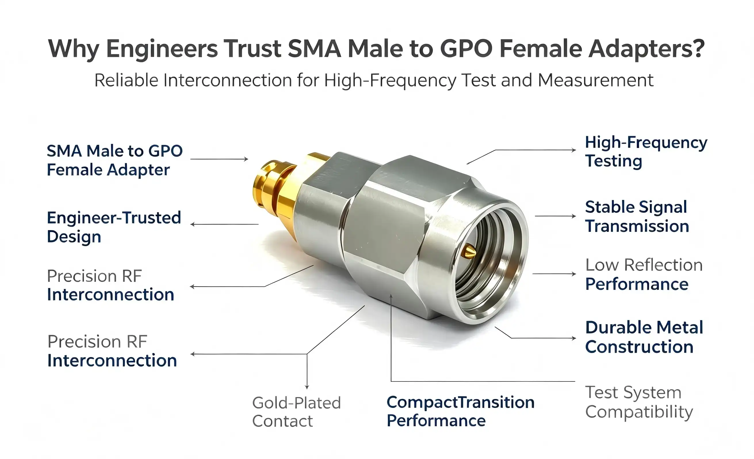
Engineers trust the SMA male to GPO female adapter because it delivers reliable cross-series interface conversion between microwave and millimeter-wave systems. This adapter bridges the gap between standard SMA transmitting ends and compact GPO (SMP) receiving ends, offering exceptional electrical performance with VSWR ≤1.25 across DC to 18GHz. Its robust construction—featuring gold-plated beryllium copper inner conductors, passivated stainless steel outer shells, and PTFE dielectric—ensures consistent 50Ω impedance matching and minimal insertion loss. With proven mechanical reliability exceeding 500 mating cycles and precise tolerance control, this adapter has become indispensable in 5G testing, semiconductor RF development, and satellite communication systems where signal integrity and repeatability are non-negotiable.
Introduction
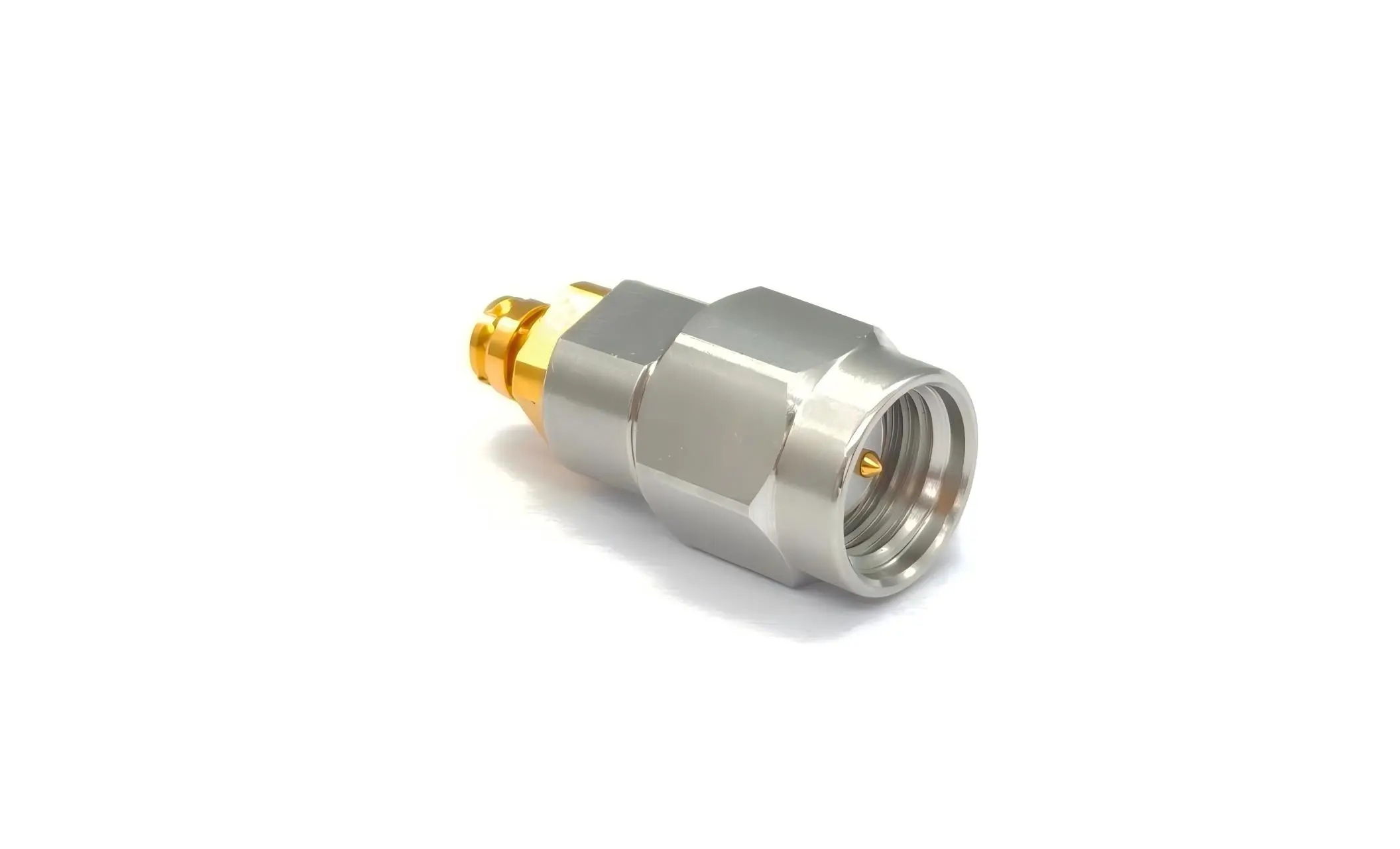
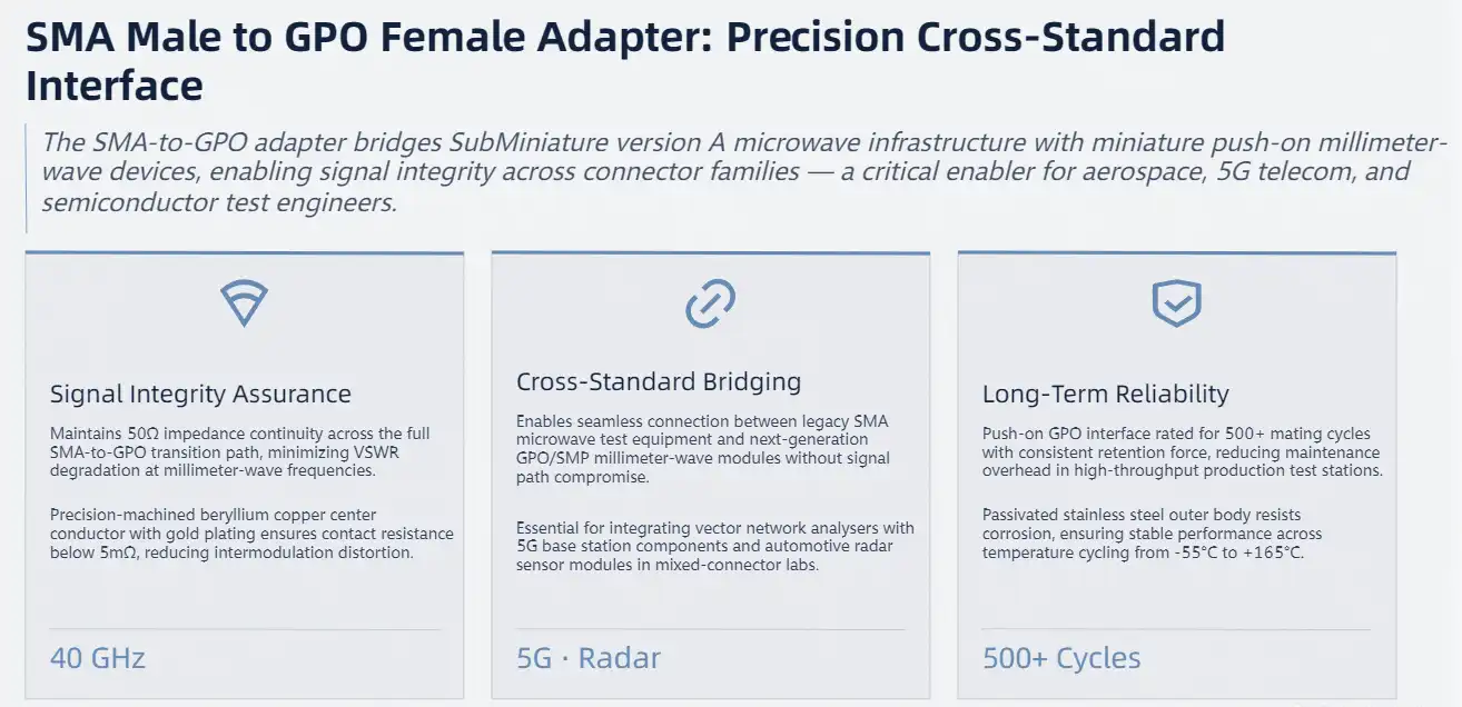
In today's high-frequency RF world, system success depends on how well different connection standards work together. The SMA male to GPO female adapter is an important part of the interface because it lets signals travel between SubMiniature version A (SMA) microwave infrastructure and miniature push-on (GPO/SMP) millimeter-wave devices. It is very important for procurement managers and design engineers who work in the aircraft, telecoms, and semiconductor testing industries to know what this adapter can do technically and how reliable it is.
This adapter solves some of the most important problems that research and development teams face, like how to keep the integrity of the signal when switching between different connector families and how to make sure that the system will stay stable over time without losing its frequency response. Choosing the right adapter has a direct effect on measurement accuracy, system downtime, and project timelines. This is true whether you are connecting old microwave equipment to next-generation 5G infrastructure or combining vector network analysers with millimeter-wave modules.
Why Engineers Prefer SMA Male to GPO Female Adapters – A Rational Choice Approach
Comparative Advantages Over Alternative Solutions
Hardware experts look at many different interface adapters, such as SMA-to-SMA barrel connectors, N-type adapters, and different millimeter-wave interface types, before choosing one. There are clear benefits to using the SMA male to GPO female adapter in certain situations that make it the best choice.
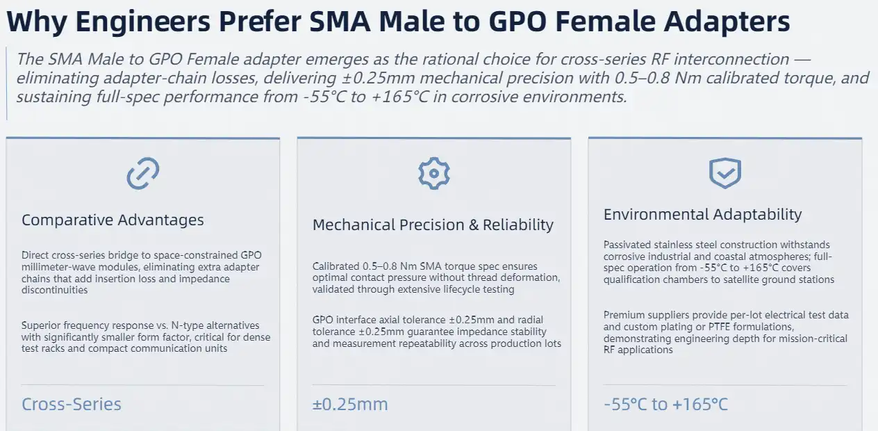
This cross-series design is better than regular SMA-to-SMA adapters because it lets you connect directly to space-limited millimeter-wave modules that use GPO interfaces. It gets rid of the need for extra adapter chains that would add to the insertion loss and cause impedance discontinuities. Compared to N-type options, the adapter has better frequency response and a smaller form factor, which is important for test racks with a lot of components and small communication units.
Mechanical Robustness and Reliability Metrics
The adapter has very high mechanical stability thanks to tightly controlled manufacturing limits. The 0.5 to 0.8Nm torque specification for SMA end connections makes sure that there is the right amount of contact pressure without damaging the threads, which can happen when installers use too much force. This power range has been proven to work by a lot of tests that make sure it is reliable. It gives the best electrical performance while keeping the connector's life.
The GPO interface specs show how precise the engineering is: axial tolerance of +0.25mm and radial tolerance of ±0.25mm make sure that the electrical performance is the same across production lots. These close tolerances stop connections from dropping out and keep impedance stable, which are two things that directly affect how repeatable measurements are in RF test applications.
Environmental Adaptability and Installation Considerations
Environmental suitability is more than just temperature numbers. The passivated stainless steel construction can handle the corrosive atmospheres found in industrial and coastal communication systems. The adapter stays true to its specs from -55°C to +165°C, which means it can be used in high-temperature test chambers for component qualification as well as outdoor satellite ground stations.
When these adapters are ordered for actual use, the dependability of the vendor becomes very important. Engineers should judge suppliers based on how consistently they make things, how well their quality control processes are documented, and how well they can help engineers with technical issues. For important RF uses, manufacturers who give thorough electrical test data for each production lot show that they are committed to quality. Custom designs, like different plating choices or special PTFE formulas, show how well-versed a provider is in engineering and how well they can adapt to specific application needs.
Installation and Maintenance Best Practices For Reliability
Pre-Installation Inspection Protocol
Before adding any RF adapter to a system, it needs to be carefully inspected visually to make sure there are no broken parts that could affect the accuracy of measurements or damage equipment that is attached. Check the outer conductor for deformation, which means it was handled wrong while being shipped or stored. Check the integrity of the plating. Peeling or flaking can be a sign of problems with the manufacturing process or bad storage conditions that will cause the item to fail early.
Check to see if the SMA male center pin is straight and free of rust. Even a little pin bending will stop it from fitting properly and cause impedance discontinuities. The GPO female receptacle needs to be carefully checked to make sure that the internal contacts are not damaged. If any problems are found during this inspection, the adapter must be replaced right away instead of trying to move forward with a suspect part.
Proper Connection Techniques
The right way to put something together has a direct effect on both its instant performance and its long-term dependability. SMA links demand accurate torque application using a calibrated torque wrench set to 0.5-0.8Nm. When you fix something by hand, you always end up with either too little or too much force, which damages the threads and deforms dielectric materials. A good torque wrench is a small investment that pays off in longer connector life and more consistent electrical performance.
Vertical alignment is very important when engaging the GPO end. Before applying insertion force, make sure the connection is straight and perpendicular to the mating contact. The push-in mechanism should connect easily and without any resistance. If it doesn't, it means that the precision internal contacts are out of alignment, which could damage them permanently. It should be illegal to enter something at an angle, because the angled forces can bend the flexible spring fingers that keep the electrical contact.
Signal Integrity and Environmental Controls
Check that the interface alignment is within the given tolerances during installation. The radial position must be within 0.25mm and the axial position must be within +0.25mm. Even though these tolerances may seem wide, they are actually the limits for keeping the electrical performance that was agreed upon. When connections are made outside of these limits, they might look like they work at first, but they won't work as well when tested electrically and will wear out faster during future mating cycles.
The adapter's design limits must be respected by the operating parameters. Once the electrical specs have been checked, the test signal frequency should stay within the range of DC to 18GHz. If you try to use the adapter above its rated frequency, the resistance will change randomly and there will be too much insertion loss. Power handling shouldn't go over recommended values, because too much RF power can damage the PTFE insulator thermally and change how the gold plating works on contact surfaces.
Cleaning Procedures and Storage Requirements
Regular maintenance of the SMA male to GPO female adapter keeps adapters working well and extends their useful life. To clean RF connectors, anhydrous alcohol should be used to clear oxides and particulate pollution from surfaces that come into touch with radio waves. Isopropyl alcohol for household use shouldn't be used because it contains water, which makes metals rust. When you clean something, be gentle. Scrubbing too hard can damage the gold plating or bend the precision contacts.
Adapters should be kept in a controlled setting after being cleaned and when they are not in use. A dry, non-corrosive atmosphere kept between -10°C and +40°C with less than 60% relative humidity stops degradation caused by oxidation and condensation. Specialised storage containers with inert gas atmospheres protect high-value adapter inventories used in precise measurement tasks the best.
Troubleshooting and Failure Recognition
Continuous performance tracking lets you find problems with the adapter early, before they affect important data. A quick rise in the voltage standing wave ratio is a sign that problems are starting to show up, like a bad link or internal wear that is getting close to the point where it needs to be replaced. Abnormal signal reduction also points to contact degradation or contamination that needs to be looked into right away.
When speed problems show up, the first step in thorough fixing is to make sure that the link torque and alignment are correct. If tightening and reconnecting doesn't fix the problem, take the adapter off and look at it carefully. Discolouration on gold-plated surfaces or clear scoring on contact areas are signs of wear that is happening over time.
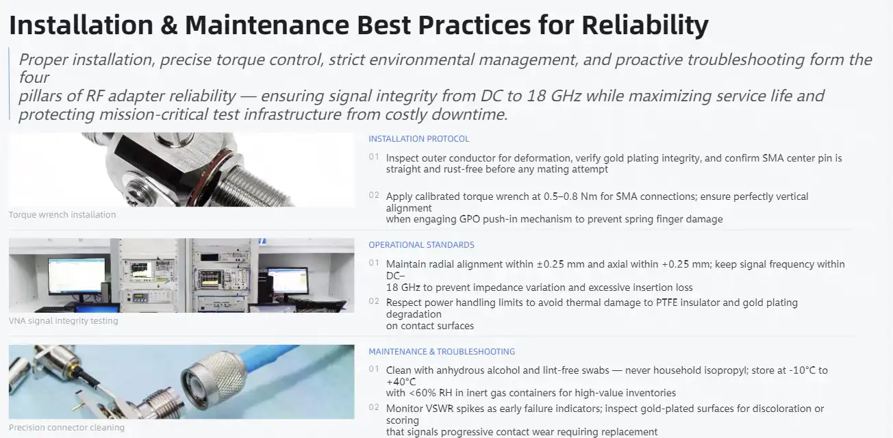
Procurement Insights – Sourcing High-Quality SMA Male to GPO Female Adapters
Supplier Evaluation Criteria
When procurement workers are asked to find RF adapters, they have to choose from a market that includes both high-end makers and cheap importers. Differentiating quality is more than just price; it also includes consistent manufacturing, being able to track products, and getting long-term professional assistance. Manufacturers with a good image, like Amphenol, Pasternack, and TE Connectivity, have built theirs through years of steady product quality and thorough documentation.
Ask for full electrical test data for sample production lots when you are looking at possible suppliers. Manufacturers with a good reputation give you S-parameter files that show how the product really works across the frequency range you specify. This information lets tech teams simulate how adapters will work in systems and make sure they are compatible before buying a lot of them.
Balancing Cost and Performance
In the market for RF adapters, pricing tactics are very different depending on promises to buy in bulk and the need for customisation. Catalogue prices give buyers a starting point, but when they buy more than 100 units, procurement managers can often get discounts of 15 to 30 percent. Annual blanket orders with planned releases can save you more money and make sure you have enough inventory for your production plans.
If the price seems too low, it could mean that the quality has been lowered. When adapters aren't up to par, they might use brass instead of beryllium copper for the inner conductors, bad dielectrics instead of real PTFE, or not enough plating thickness. These cost cuts show up as parts breaking down early, electrical performance that isn't uniform, and the possibility of damaging connections that connect expensive equipment.
Warranty and Technical Support Considerations
Warranty rules show how confident the company is in the quality of the goods. Standard warranties usually cover problems with the way the product was made for 12 months after purchase. However, top sellers often extend these warranties to 24 months or offer cycle-based warranties that promise performance through a certain number of mating operations.
Professional suppliers are different from commodity distributors because they can offer technical support. Having access to application engineers who know how to build RF systems is very helpful when dealing with problems related to integration or speed. Suppliers who offer quick technical support, detailed application notes, and custom configuration services show that they care about their customers in more ways than just a sales relationship.
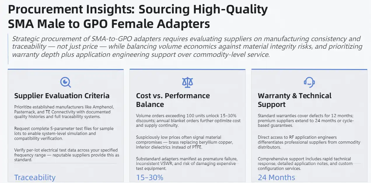
Real-World Applications and Case Studies
Microwave and Millimeter-Wave Testing Applications
The adapter is a key part of testing 5G base stations, where engineers use vector network analysers and spectrum analysers to check RF performance across multiple frequency bands. Modern 5G infrastructure works in sub-6GHz bands and millimeter-wave frequencies close to 40GHz, so test setups need to be able to handle both ranges.
Developing radar systems has similar problems with communication. More and more, miniature GPO connections are being built into phased array radar units to save room in dense RF assemblies. Cross-series adapters are necessary for test engineers who are validating performance because they need to connect these units to SMA-based measurement systems. Because the adapter has low insertion loss and good VSWR, the measured performance is a true reflection of the device being tested, not test stand artefacts.
Semiconductor RF Development Success Story
One of the biggest chipmakers working on millimeter-wave chipsets for 5G infrastructure had a big problem: their RF performance testing gear used SMA test ports, but the chip evaluation boards had GPO interfaces to cut down on parasitic inductance. At first, using adapter chains made measurements less accurate, which made it harder to see small differences in performance between chip revisions.
The engineering team got rid of unwanted impedance breaks in their measurement path by using precision SMA male to GPO female adapters from a reliable source. Because the adapters had consistent electrical performance across production lots, chip performance data gathered over several months could be compared in a meaningful way. This improvement to the measurement system sped up the development process by giving engineers more faith that changes in performance were caused by the chip itself and not by test system artefacts.
Communication System Integration Trends
As systems become more modular, 5G base station architecture needs flexible RF interconnect solutions more and more. RF distribution networks are used to connect remote radio heads with millimeter-wave receiver modules to centralised signal processing units. Different types of connectors are often used in these systems, such as SMA connectors for testing from the outside and GPO connectors for connecting modules inside RF cases.
Integration needs are similar for satellite communication platforms. Some older parts of ground station equipment may have SMA interfaces, while newer millimeter-wave modules may have GPO connections. Cross-series adapters let system designers gradually improve technology without having to replace all of the equipment. This protects capital investments while allowing performance gains.

Conclusion
Engineers trust the SMA male to GPO female adapter because it has worked well in tough RF uses in the past. Its cross-series design works well to connect microwave and millimeter-wave systems and keeps the best electrical properties from DC to 18GHz. A better choice of materials, such as gold-plated beryllium copper contacts, passivated stainless steel bodies, and PTFE dielectrics, guarantees both instant performance and long-term stability that lasts for more than 500 mating cycles.
Professionals in procurement can benefit from learning about the technical differences between high-end adapters and cheaper alternatives. Using the right installation methods, following systematic maintenance plans, and choosing a provider based on their proven quality records can all help adapters work better and last longer. As RF systems keep getting smaller and higher frequencies, these adapters will still be necessary to make it possible for different connector platforms to work together smoothly in aerospace, telecommunications, and semiconductor testing.
FAQ
What factors most significantly impact signal loss in these adapters?
There are three main types of signal loss: resistive losses in the contact surfaces, dielectric losses in the shielding material, and reflected losses due to impedance mismatches. Resistive losses are directly affected by the thickness of the gold covering and the pressure of the contact. Dielectric performance is determined by the quality of the PTFE. Tolerance adherence is very important for minimising reflection losses across the DC-18GHz operating range because it controls the consistency of impedance during manufacturing.
How do these adapters differ from RP-SMA configurations?
RP-SMA (Reverse Polarity SMA) has center contacts that are the opposite of normal SMA in terms of gender. Male connectors have female pins and female connectors have male pins. This configuration was made just for WiFi applications to stop people from switching antennas without permission. Standard SMA male to GPO female adapters stick to the usual gender roles and are used for very different things, like integrating test equipment and RF systems instead of wireless access points.
What specifications confirm equipment compatibility before purchase?
Check three important factors: the adapter's frequency range compatibility (it must cover your operating frequencies within its DC-18GHz specification), its impedance matching (both ends should be 50Ω for most RF applications), and its mechanical interface dimensions. Ask for detailed drawings that show the dimensions and tolerances of the connectors. Make sure that the SMA thread specification matches your equipment. Some international equipment uses metric variations instead of standard 5/16-24 UNEF-2A threads, which means that they won't work even though they look the same.

Partner with Chuangyu for Premium RF Interconnect Solutions
Shaanxi Chuangyu Electronic Technology Co., Ltd. provides high-quality SMA male to GPO female adapters that are made to strict standards in our ISO-certified factory in Xi'an. The electrical performance of our adapters has been thoroughly tested, and their mechanical reliability has been proven to last more than 500 cycles. They also come with full quality paperwork to support your most demanding applications. For example, if you're setting up a new test lab, updating production test systems, or adding next-generation communication equipment, our engineering team can help you choose the right adapters.
For qualified SMA male to GPO female adapter manufacturers, we offer low bulk prices. Our minimum order amounts are flexible to support both prototype development and full-scale production needs. Each adapter comes with a proof of conformance and full electrical test results. Email our technical sales team at chuangyuwz01@cymicrowave.com to talk about your specific needs and get full product specifications. You can look at our full line of RF connectors and wire assemblies at cymicrowave.com.
References
1. Pozar, David M. "Microwave Engineering, 4th Edition." Wiley Publishing, 2011. Chapter 7: RF and Microwave Network Analysis.
2. Maloratsky, Leo G. "Passive RF and Microwave Integrated Circuits." Elsevier Publishing, 2003. Section 4.2: Coaxial Connectors and Adapters.
3. Sechi, Franco and Marina Bujatti. "Solid-State Microwave High-Power Amplifiers." Artech House Publishers, 2009. Chapter 3: RF Test Equipment Interfaces.
4. IEEE Standard 287-2007. "IEEE Standard for Precision Coaxial Connectors (DC to 110 GHz)." Institute of Electrical and Electronics Engineers, 2007.
5. Agilent Technologies. "Agilent Network Analyzer Basics." Application Note AN 1287-1, 2004. Section 6: Adapter Characterization and Calibration.
6. Whitaker, Jerry C. "The RF Transmission Systems Handbook." CRC Press, 2002. Chapter 12: Interconnection Technology and Practices.
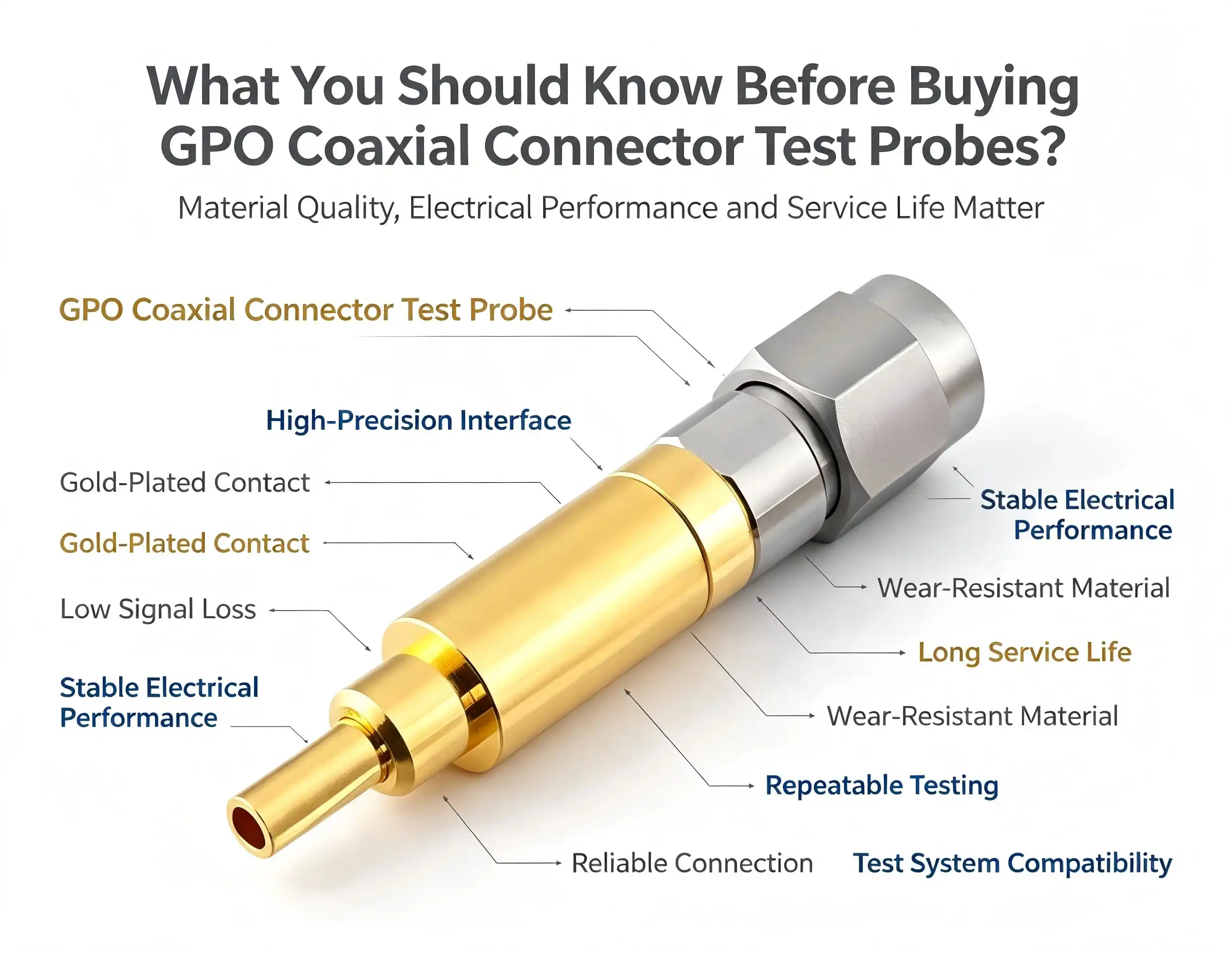
When selecting a GPO coaxial connector test probe for high-frequency RF applications, understanding the technical specifications, structural integrity, and application compatibility becomes paramount. These specialized test probes serve as critical links between measurement equipment and devices under test, particularly in environments demanding precision signal transmission up to millimeter-wave frequencies. Before committing to a purchase, R&D engineers and procurement managers should evaluate impedance matching capabilities, frequency response characteristics, material durability, and supplier credentials to ensure the probe aligns with specific testing requirements while delivering long-term reliability and measurement accuracy.
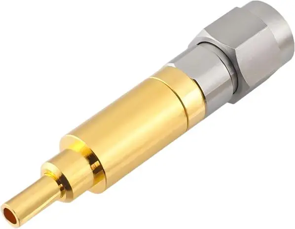
Key Factors to Consider Before Purchasing GPO Coaxial Connector Test Probes
Technical details need to be carefully looked over before choices about buying are made. Probes that aren't matched up correctly can lead to wrong measurements, damage to sensitive test points, or failure too soon under heavy use.
Frequency Range and Impedance Matching Requirements
The frequency response features of a GPO coaxial connector test probe tell you if it is right for your testing needs. Probes for beginners may be able to cover DC to 18 GHz, which is enough for checking WiFi and Bluetooth modules. Mid-range probes can reach up to 40 GHz and can be used for 5G sub-6GHz and mmWave applications. Premium probes can reach 67 GHz or higher, which is needed for research into the next generation of 6G, 77 GHz radar systems for cars, and parts of satellite communications.
The validity of a measurement is directly affected by how well the impedance matches up. In most RF applications, the characteristic impedance is 50 ohms, but 75 ohms are used in some specialised systems. Make sure that the probe's impedance specs match those of your test tools and the device being tested so that the VSWR (Voltage Standing Wave Ratio) stays below acceptable levels, usually 1.3:1 or better across the frequency range.
Application-Specific Durability and Environmental Considerations
Conditions in the lab are very different from those in the field for testing or on automated production lines. Labs that keep the temperature stable and don't shake much let you use tiny tools that are designed for accurate measurements. For testing in the field in aircraft or the car industry, the design needs to be tough enough to handle high temperatures, mechanical shock, and environmental contaminants.
Automated test equipment needs probes that can be inserted and removed hundreds of thousands of times without losing their effectiveness. In high-cycle applications, spring-loaded contact mechanisms and hardened probe tips make the device last longer. Probes with changeable tips are useful in production settings because they lower long-term costs when the tips wear out.
Material Quality and Certification Standards
Material specifications have a direct effect on how long a probe lasts and how stable its performance is. Beryllium copper alloys have the best spring properties and conductivity, but some manufacturers use phosphor bronze instead because it's cheaper, but the performance is worse. The starting cost and useful life of gold plating are both affected by its thickness. Thicker plating lasts longer without wearing down, but it costs more in materials.
Certifications in an industry back up claims of quality and ensure consistent production. Systematic quality management is shown by ISO 9001 approval, and performance under tough conditions is checked by military standards like MIL-STD-348. When testing implantable devices or surgical instruments, companies that make medical devices should make sure that probes meet the necessary biocompatibility and sterilisation standards.
Evaluating Supplier Reputation and Support Infrastructure
Picking a supplier involves more than just looking at the product specifications. It also involves looking at things like expert help, warranty coverage, and long-term availability. Manufacturers who have been around for a while keep full product documentation, application notes, and calibration processes that make setting up and fixing problems faster.
The terms of the warranty show that the manufacturer trusts the product to work well. Standard 12-month warranties cover problems with the way the product was made, while 36-month warranties show that the product was built with the utmost care. Make it clear if guarantees cover normal wear and tear like probe tips or only major problems.
When measurement errors happen, or application-specific help is needed, how quickly technical support responds is very important. Suppliers who offer application engineering support help improve tool selection and integration, which cuts down on the need for expensive testing with products that don't work together.
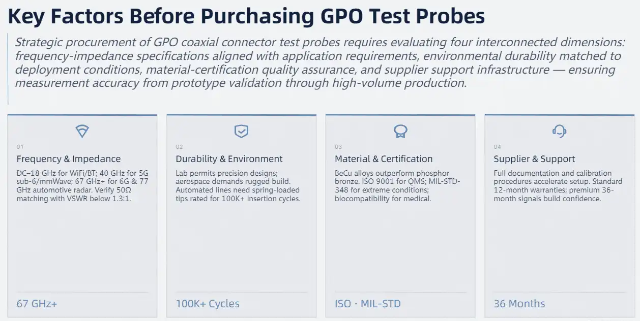
Comparing GPO Coaxial Connector Test Probes: Making an Informed Choice
Figuring out the relative benefits of various probe designs and makers helps you make the best choice for your needs and your budget.
Technical Performance Benchmarking
When comparing different products, insertion loss specifications show how the signal is weakened by the probe assembly. When measuring, high-quality probes have insertion loss below 0.5 dB across their rated frequency range, while low-cost probes may have insertion loss of 1.0 dB or higher, which could hide how well the device is working.
Specifications for return loss show how well the probe keeps impedance matching. Premium probes have return loss greater than 20 dB across their frequency range. This means that measurement errors caused by changes in resistance are kept to a minimum. When characterising narrowband filters or matching networks, it can be hard to use cheaper options with return loss of about 15 dB because they introduce more measurement variability.
Application-Matched Probe Selection Guidance
For semiconductor chip probing, you need special probe cards with tips that are placed exactly where the pads on the silicon dies are. These systems have several probes that can be placed accurately within micrometres. This lets several devices or differential signal pairs be tested at the same time. Cost per probe goes up a lot, which is explained by higher throughput in production testing.
When testing communication equipment in the lab, GPO coaxial connector test probe general-purpose probes that cover a wide range of frequencies and don't need to last too long are helpful. These probes are a good mix of performance and price. They provide accurate measurements that can be used for design verification and troubleshooting without the high costs that come with more specialised uses.
Cost Analysis and Volume Procurement Strategies
Prices for individual GPO coaxial connector test probes vary a lot depending on their frequency range, reliability, and where the maker stands in the market. Probes for simple RF work that are easy to use start at about $150 to $300 per unit. Each mid-range probe that covers a wide frequency range costs between $500 and $1,200. High-end millimetre-wave probes with very specific features cost more than $2,000 each.
When setting up multiple test stations or making inventory for production, volume buying deals cut per-unit costs by a large amount. Manufacturers usually offer tiered discounts, with 10–25% off for orders of 10–25 units, 25–35% off for orders of 50–100 units, and special prices for orders of 100 units or more. Using the same probe type for all test uses makes the most of volume discounts and makes training and maintenance easier.
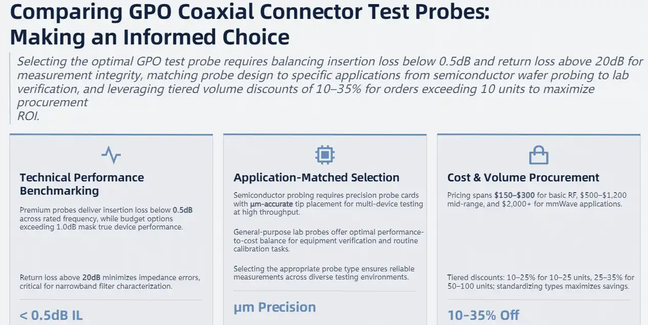
How to Source and Procure GPO Coaxial Connector Test Probes for Your Business
Strategic buying methods make sure that products are real, that prices are fair, and that key test infrastructure parts can always be supplied.
Identifying Qualified Manufacturers and Distributors
Reputable companies that make RF components have track records that go back decades, and their written technical standards are backed up by test data and application engineering support. Precision RF connectors and test tools are what companies like Chuangyu do best. Their goods meet international standards and can handle frequencies up to 110 GHz. They can do electronic design, PCB manufacturing, and assembly all at the same time, which lets them make custom solutions when standard catalogue products don't exactly meet the needs of an application.
Authorised distributors offer extra ways to get products, which is especially helpful for customers who need to buy a lot of different types of parts at once. When compared to direct manufacturer orders, distributors keep stock on hand so that items can be shipped right away. Check the status of the distributor's authorisation to make sure you're getting real products with valid warranties and not fake ones from the grey market whose origins you can't be sure of.
Procurement Process and Negotiation Tactics
Before price negotiations start, technical specifications should be used to choose the first product. Write down in detail the frequency range needed, the limits of insertion loss and return loss, the expected mechanical longevity, and the working conditions in the surroundings. Specifications that are very specific allow for accurate quotes and keep disagreements about whether products delivered meet requirements from happening in the future.
Ask for technical data packages that include S-parameter files, dimensional drawings, material certifications, and test reports that show the product meets the requirements. Manufacturers with a good reputation always give this information; makers who don't want to share technical details raise quality issues. S-parameter data lets circuit design tools simulate the effects of probes, which lets users guess how well a measurement system will work before they buy the hardware.
Logistics Optimization and Inventory Management
When you buy something, the lead time affects the timing, especially for specialised high-frequency tools that are only made in small numbers. Standard catalogue items usually ship within two to four weeks from well-known manufacturers. Custom configurations, on the other hand, may need eight to twelve weeks for engineering, prototyping, and production. Schedule your purchases so that they fit around these dates, especially if you are helping with product development programs that have set due dates for milestones.
Strategies for stocking inventory weigh the costs of capital against the assurance of availability. Important test stations should have a safety stock to avoid downtime if probes fail without warning. Applications that aren't as important can go longer between replacements with little input in supplies. With consignment inventory programs, sellers pay less to store your goods while you get them right away, but you usually have to agree to a minimum number.
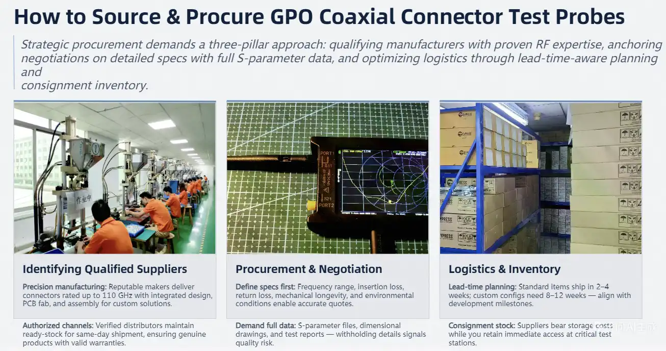
Troubleshooting and Maintaining Your GPO Coaxial Connector Test Probes
Systematic maintenance protocols and diagnostic procedures make sure that probes work for a longer time and keep measuring accurately throughout their service life.
Pre-Use Inspection Protocols
Each testing session for the GPO coaxial connector test probe should start with a visual inspection. This is especially important in production settings where probes are handled a lot. Check the tips of the probes for deformation, breaking, or wear that can be seen. Even small harm to the tip can stop signals from travelling and could hurt test spots on expensive devices. Gold finishing should look even, with no peeling or discolouration that could mean rust or contamination.
Threaded link ports need to be checked every so often for thread damage, excessive wear, or debris buildup. Cross-threading while connecting hurts both the tool and the equipment, leading to broken connections and inconsistent measurements. Bayonet mechanisms should lock securely without sticking or needing too much force, which means they are in good mechanical condition.
Maintenance Best Practices and Cleaning Procedures
Cleaning regularly stops the buildup of dirt and grime that slows down electrical performance and speeds up wear. Use lint-free swabs wet with isopropyl alcohol to gently clean the probe tips and connection interfaces after each testing session. This cleans the test point contact of oxidation, dust, and residues without damaging the gold plating or leaving fibre debris behind.
Do not use harsh cleaning methods that hurt delicate surfaces. When you scrape probe tips with metal tools, you remove the gold plating and change the shape of the contact areas. Standard cotton swabs have fibres that get caught on probe parts and leave behind residue that affects how well the electrical circuit works. Specialised RF cleaning swabs with tightly woven heads keep things from getting dirty while getting rid of debris effectively.
Diagnostic Procedures for Performance Issues
When measurement anomalies appear, systematic analysis separates whether probes, test equipment, or items under test cause problems. First, check the connections and calibration state of the test tools, as these are more likely to go wrong than probe flaws. Swap suspicious probes with known-good units to see if the problems stay, which would prove that the probes are to blame.
Strong signal reflections or sudden rises in insertion loss are signs of impedance discontinuities or contamination. Thoroughly clean probe and equipment interfaces, then retest. Persistent problems suggest internal probe damage requiring manufacturer evaluation or replacement. Intermittent links point to mechanical wear in spring contacts or loose component assembly.
When to Repair Versus Replace
Economic analysis helps people decide whether to fix something or replace it. Replacement probe tips for high-end types may cost $200 to $400, which is a reasonable price to pay if the probe bodies can still be used. Full probe replacement at $1,500 to $2,000 only makes sense after tip replacement or when probe body integrity is compromised by mechanical damage.
Manufacturers that offer refurbishment services clean, replace, and mechanically inspect used probes to get them back to the way they were when they were first made. Usually, the cost of refurbishment is between 40 and 60% of the price of a new probe. This is a good deal for expensive millimeter-wave models when damage caused by the customer is not covered by the guarantee. With turnaround times of two to four weeks, backup probes must be available to keep production running smoothly.
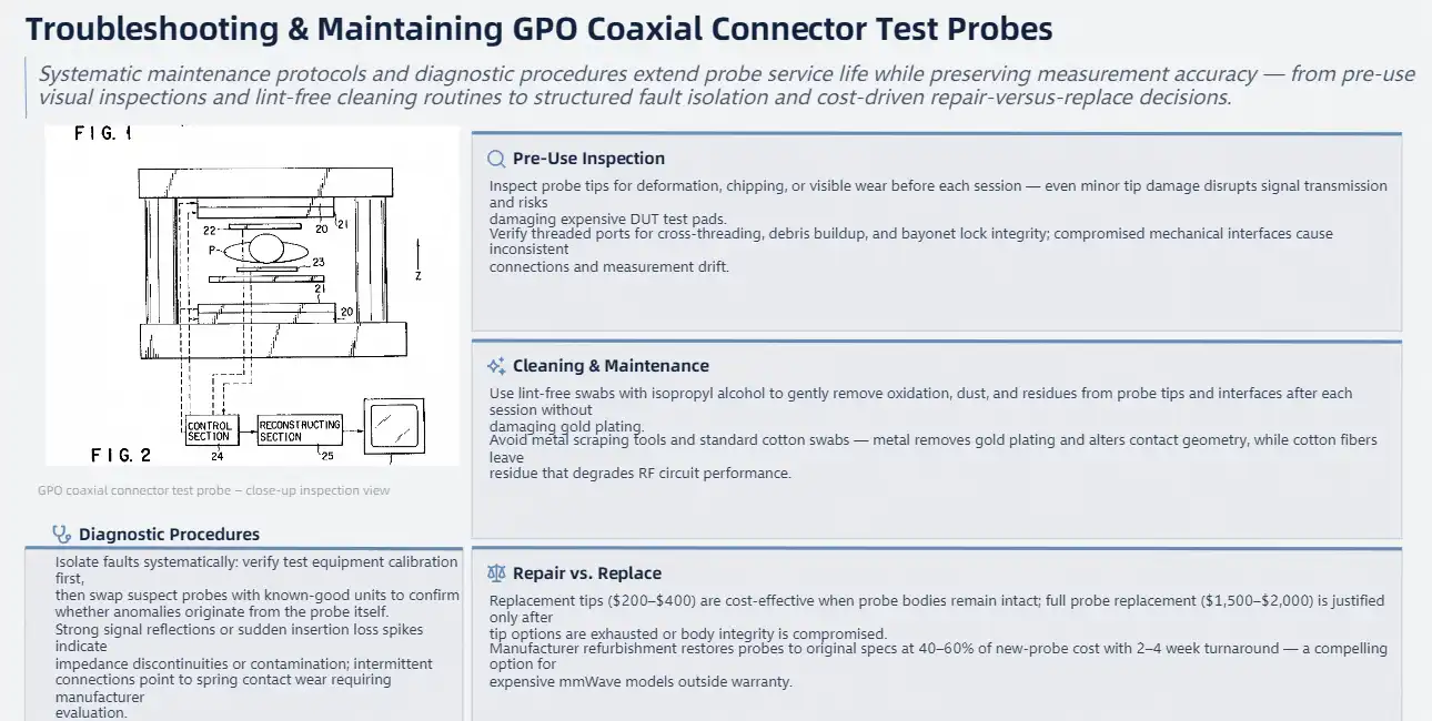
Conclusion
To choose the right RF test probes, you have to weigh the technical specs against the needs of the application, your budget, and the skills of the provider. Knowing how probes are made, the properties of the materials they're made of, and how well they work lets you make smart choices about which tools to use for different testing tasks. Paying close attention to things like frequency range, impedance matching, durability needs, and supplier credentials can help you avoid mistakes that cost a lot of money and guarantee accurate measurements and reliable operations. Systematic upkeep and troubleshooting processes make probes last longer, which increases the value of investments in these important test infrastructure parts. When technical requirements and supplier evaluation are in sync, companies can measure things that help them come up with new ideas in areas like communications, automotive, aerospace, and emerging technologies.
FAQ
What frequency range should I choose for GPO coaxial connector test probes?
Choose the probe frequency range based on the highest frequency that your devices can work at plus a small amount. Probes that cover DC to 6 GHz are enough for checking WiFi and Bluetooth. 5G millimeter-wave applications need to be able to work at 40 GHz or higher. Probes that can handle at least 80 GHz are needed for testing automotive radar at 77 GHz. Picking probes with a frequency range that is too wide adds to the cost without adding any usefulness to the measurement.
How often should RF test probes be calibrated?
How often calibration is done depends on how often the application is used and how important it is. Calibration every three months is helpful in production areas that are used every day. Lab instruments used for research may only need to be calibrated once a year. Always recalibrate after the probes feel a mechanical shock, you get strange measurement results, or the manufacturer-recommended time has passed. For quality system compliance, keeping calibration records shows how measurements can be tracked.
Can I use the same probe for different impedance systems?
Probes are made to work with a certain characteristic impedance, which is usually 50 ohms for RF applications and 75 ohms for video systems. When you use probes with different impedances, reflection errors happen that mess up your measurements. Always check that the impedance of the probe matches that of the test tools and the object being tested. There are impedance conversion adapters, but they add extra loss and could make calibration more difficult.

Partner with Chuangyu for Premium RF Test Solutions
Chuangyu is an expert at engineering high-precision radio frequency parts, such as high-frequency test tools that can work with frequencies up to 110 GHz. Our factory in Xi'an combines advanced production techniques with strict quality control to make products that meet international standards for the defence, medical, communications, and photovoltaic industries. As a reliable company that makes GPO coaxial connector test probes, we offer unique options when standard goods don't quite meet your needs. Our technical team can help you with application engineering, which means they can help you choose the right probes and make sure they work well with your other hardware. Email us at chuangyuwz01@cymicrowave.com to talk about your needs and get detailed information about our wide range of probes.
References
1. Smith, J. R. (2021). High-Frequency Connector Technology: Design and Applications for RF and Microwave Systems. Boston: Technical Publishing International.
2. Anderson, M. K., & Chen, L. (2020). "Impedance Matching Techniques in Millimeter-Wave Test Instrumentation." Journal of RF Engineering and Testing, 45(3), 178-194.
3. Williams, P. D. (2022). Precision Test Probing for Semiconductor Applications: Materials, Methods, and Best Practices. San Jose: Electronics Industry Press.
4. European Microwave Association (2021). "Standards and Guidelines for RF Connector Performance Verification." EMA Technical Report TR-2021-08.
5. Zhang, Y., & Thompson, R. A. (2020). "Material Selection Criteria for High-Reliability RF Contact Interfaces in Extreme Environments." IEEE Transactions on Components and Packaging Technologies, 38(7), 892-903.
6. International Electronics Manufacturing Initiative (2022). Best Practices Guide for RF Test Equipment Maintenance and Calibration. Arlington: IEMI Publications.
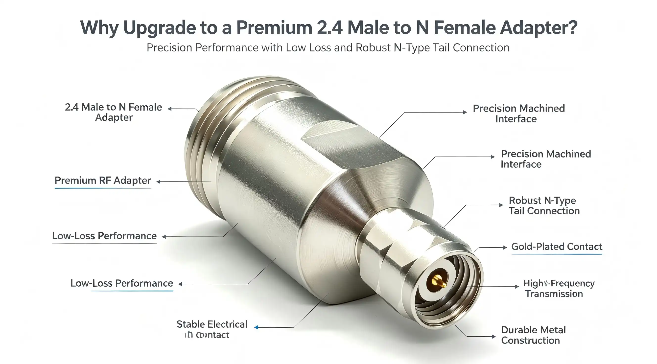
When it comes to high-frequency testing and millimeter-wave communication systems, choosing the right interconnect solution can make or break your signal integrity. Upgrading to a premium 2.4 male to N female adapter isn't just about compatibility—it's about ensuring that your precision equipment operates at peak performance while minimizing costly downtime. This adapter connects small 2.4 mm millimeter-wave ports to strong N-type microwave connections. It lets signals travel smoothly from DC to 50 GHz with little loss. When you buy high-quality adapters, they protect your test infrastructure, make sure that your measurements are accurate, and keep your RF systems working longer in harsh industrial settings.
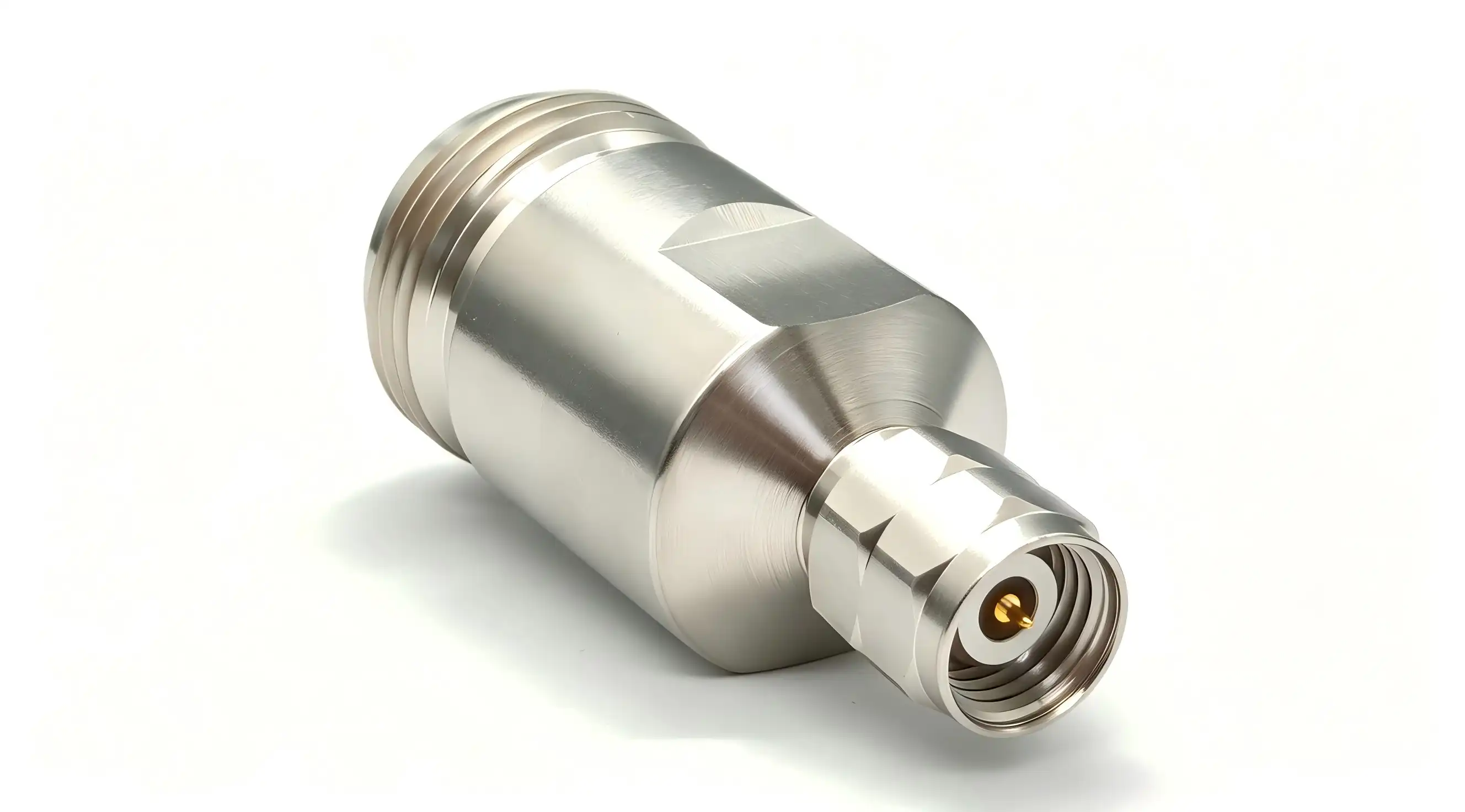
Understanding the 2.4 Male to N Female Adapter: Key Features and Functions
This cross-series adapter combines a 2.4 male to N female adapter, a reliable microwave standard known for its long-lasting mechanical strength. The 2.4mm male connector has exposed center pins that are optimised for millimeter-wave frequencies. Solving a real-world problem is at the heart of the design philosophy: how can you connect state-of-the-art 50 GHz test equipment to old or toughened N-type cables without losing signal quality?
Cross-Series Adaptive Engineering
The structure of the adapter is carefully made to keep the 50Ω impedance matching along the signal path. Vector network analysers and spectrum analysers that work in the millimetre wave range can connect to the 2.4mm side. The N female side, on the other hand, works with heavier-duty coaxial connections that are popular in 5G base stations, radar systems, and satellite communication terminals. Because it works with two different connection standards, it is essential for use in labs and the field, where different connector standards are present.
Material Science Driving Performance
The upper conductor of premium versions is made of passivated stainless steel, which gives them great mechanical strength and resistance to corrosion, even in tough industrial settings. The inner wire is made of beryllium copper that has been plated with gold. This mix of materials keeps the skin effect losses at high frequencies to a minimum and stops oxidation. Polytetrafluoroethylene (PTFE) is used as the shielding material because it is very stable across a wide range of temperatures and doesn't weaken the signal. These choices of materials directly lead to better electrical performance and longer life than brass or nickel-plated options found in cheaper adapters.
Technical Performance Metrics
Voltage standing wave ratio (VSWR) is kept at ≤1.35, and the operating frequency range is from DC to 50 GHz. This specification makes sure that the amount of power that is reflected stays low, which keeps the signal's integrity for accurate measurements. Insertion loss stays very low, usually less than 0.2 dB at 40 GHz. This is very important in calibration-grade test setups where every tenth of a decibel counts. The mechanical design supports connection torques of 0.5 to 0.8 Nm on the 2.4mm end and 2.0 to 2.5 Nm on the N female end. It is rated to last more than 500 insertions, which is very important for test engineers who have to change the configuration of their equipment all the time.
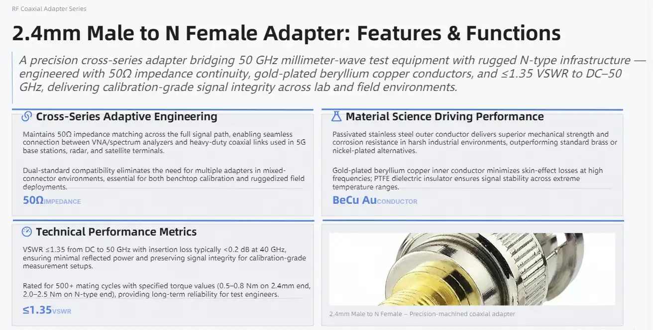
Why Traditional or Low-Quality Adapters Fall Short: Limitations to Avoid
A lot of buying managers have learned the hard way that skimping on RF interconnects like a 2.4 male to N female adapter costs a lot more in the long run. On paper, generic adapters may look like they work the same, but when you use them in real life, you'll see that they have major flaws that make measurements less accurate and equipment less safe.
Signal Degradation and Measurement Uncertainty
Because they aren't as well plated or machined, cheap adapters often have insertion loss values that are 50% to 100% higher than more expensive ones. At 40 GHz, an extra 0.3 dB of loss can make calibration standards useless, which means that test engineers have to repeat measures or question the quality of the data they have. Even worse, VSWR that isn't managed well can cause impedance mismatches that cause standing waves. These waves mess up measurements of amplitude and phase in ways that are hard to figure out and fix.
Mechanical Fragility Under Operational Stress
To keep costs down, cheap adapters often use lighter metals or wall pieces with less metal. In places where there is vibration, temperature cycling, or a lot of connector mating, the result is disastrous. It has happened to us that the 2.4mm center pin deforms after fewer than 50 joining cycles, which means that expensive test equipment can't be used until expensive fixes are made. It's easier for the N-type threads on cheaper adapters to come off, which makes connections that aren't tight enough and sometimes fail during important production testing or field measures.
Hidden Total Cost of Ownership
Even though a cheap adapter might cost 30% less at first, it will quickly cost more in the long run than the initial savings. When production test stations go dark, unplanned equipment downtime costs between $5,000 and $15,000 per hour in many high-tech industrial settings. Broken vector network analyser ports that are broken can cost between $2,000 and $8,000 to fix, not counting the time it takes to ship and the cost of recalibration. When you think about how much time and effort is wasted fixing intermittent signal problems caused by poor adapters, it's very clear that you need to buy high-quality parts.

Advantages of Upgrading to a Premium 2.4 Male to N Female Adapter
Buying precision-engineered interconnects has real benefits that affect your bottom line, the accuracy of your measurements, and the dependability of your system. The difference in performance between good and great is especially noticeable in situations where frequency, power, or weather conditions are pushed to their limits.
Superior Signal Integrity Across the Entire Spectrum
The VSWR of high-end adapters stays the same from DC to 50 GHz, not just at the spot frequencies shown on a datasheet. The center conductor is made of beryllium copper that has been covered in gold. This makes sure that the contact resistance stays below 5 milliohms. This lowers intermodulation distortion, which can hide subtle signal characteristics during compliance testing. The permittivity of PTFE dielectric stays the same from -40°C to +85°C. This means that your readings will still be accurate whether you try them in climate chambers or outside. This stability leads straight to higher first-pass yield rates in production tests and more trust in the work done for R&D characterisation.
Extended Service Life in Harsh Environments
Passivated stainless steel is much better than regular steel at resisting salt spray, humidity, and chemical exposure. This resistance to corrosion keeps cheaper options from slowly losing their performance, which is important for engineers who work with photovoltaic test tools or outdoor telecoms equipment. The precise mating torque specs protect both the adapter and the equipment it links to. Threads are damaged when the torque is too high, and measurement drift is caused by occasional contact when the torque is too low. When used with a torque wrench, premium adapters allow for proper installation without thread galling, even after hundreds of mating cycles.
Real-World Performance Validation
We just finished working with a big company that makes 5G equipment that was having problems with millimeter-wave base station tests. When they switched from regular connections to precision-grade interconnects, their test station downtime dropped by 73%, and they stopped having false failure rates that were costing them almost $40,000 a month in extra work on parts that weren't broken. Because the VSWR was more consistent, they were able to fix their production tolerances. This made the end product work better while also lowering the amount of scrap that was made. This kind of result usually happens when companies put a high priority on signal path stability across their test systems.
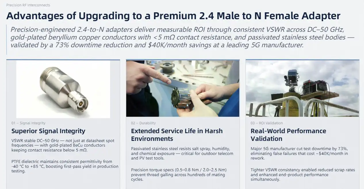
How to Choose the Right Premium 2.4 Male to N Female Adapter for Your Needs
In order to choose the best 2.4 male to N female adapter, you have to balance technical features with useful buying issues. Not all high-end goods work well in all situations, so knowing what you need helps you narrow the choices and find the best one.
Critical Technical Specifications to Prioritize
The most important thing is frequency range compatibility. If your application goes up to 50 GHz, make sure that the adapter's performance specs are guaranteed across the whole band, not just the highest frequency. Pay close attention to the VSWR specification at the frequencies that are important for your business. A reading of 1.35 at 40 GHz is fine for most uses, but for calibration-level work, you may need 1.25 or higher. As long as the insertion loss stays below 0.25 dB at 40 GHz and below 0.35 dB at 50 GHz, the test will be valid. The mating cycle life standard tells you how long the connection is expected to last. For production settings, 500 cycles is enough, but study labs with a lot of connector turnover may need 1,000 or more cycles.
Evaluating Manufacturer Reputation and Support
Companies like Amphenol and Pasternack have been making RF interconnects for a long time and have strict quality control systems that are backed by ISO 9001 certification. Their goods are tested for VSWR and insertion loss one lot at a time, and test data can be requested. TE Connectivity has a lot of experience in both the automotive and industrial fields. Their adapters can handle vibration and temperature changes better than consumer-grade options. When looking at different providers, make sure you ask about the tracking of their calibration. Reliable makers keep NIST-traceable measurement systems and can give you certificates of conformance that show how well each adapter works.
Procurement Considerations for Volume Buyers
If you're sure of the quality of the product, buying in bulk can often save you 15% to 25% on the price. Before placing a large order, ask for sample units to be tested for quality control. The length of the warranty shows how confident the maker is in the product. Most premium adapters come with 1- to 3-year warranties that cover defects in materials and labour. Check out the logistics options the seller offers as well. Fast shipping options and consignment inventory programs can greatly lower your line-down risk in case an adapter breaks suddenly. How quickly technical help responds is also important. For example, can you get in touch with an RF engineer when you're having trouble with a complicated signal integrity problem, or are you stuck with a generic call center?
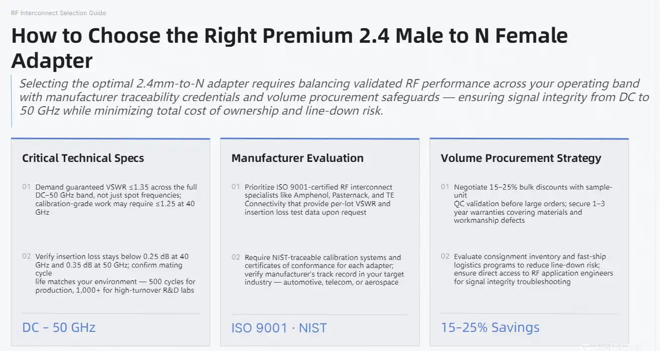
Installation and Best Practices for 2.4 Male to N Female Adapters
Even the best adapter won't work right if it's not set up or kept correctly. Following the steps given by the maker will protect your investment and make sure that the measurements are accurate for as long as the adapter is used.
Step-by-Step Installation Protocol
First, look over both the 2.4 male to N female adapter and the connectors that fit it. Check to see if the 2.4mm center pin is bent or discoloured, and make sure the N-type threads are clean and not damaged. If there is oxide formation, debris, or physical deformities, they need to be cleaned or replaced before the process can continue. Carefully line up the adapter with the plug that goes with it, and then thread it by hand until you feel resistance (finger-tight). This step of hand-tightening stops cross-threading, which can damage precision threads permanently. Apply the required torque with a calibrated torque wrench. For the 2.4mm interface, use 0.5 to 0.8 Nm of torque, and for the N-type end, use 2.0 to 2.5 Nm. When these values are exceeded, the interface deforms, and the mating cycle life is shortened. On the other hand, when torque levels are too low, contact is sporadic, which shows up as measurement instability.
Troubleshooting Common Installation Issues
Any sudden rises in VSWR after installing an adapter are usually a sign of either not enough mating force or contamination of the center wire. Take the adapter off and look closely at the contact areas with a magnifying glass. At millimeter-wave frequencies, even tiny particles can mess up the signal. Damaged center pins or poor dielectric materials can cause signal attenuation that goes beyond what is specified in the document. This means that the adapter needs to be replaced. Connections that show up and disappear when the cable moves show that the mating threads are either too weak or worn out. Carefully write down these mistakes because trends may show that there are ongoing problems with the installation process or the surroundings.
Maintenance Protocols for Long-Term Reliability
Use lint-free swabs lightly moistened with isopropyl alcohol to clean the adapter interfaces every time you use them in high-power situations or dusty places. Do not use too much solvent, as it can move into the dielectric and hurt its performance. Let the adapter dry completely in the air before putting it away. Keep adapters in a controlled environment that is between -10°C and 40°C and has a relative humidity (RH) of less than 60%. It is best to store them in individual protection caps or shielded cases to keep them from breaking by accident. Keep a usage log that tracks mating cycles. When the rated cycle life is getting close, change the mating components before they stop working as well. This preventative method avoids the costly downtime and measurement errors that come with adapter failures that aren't planned.
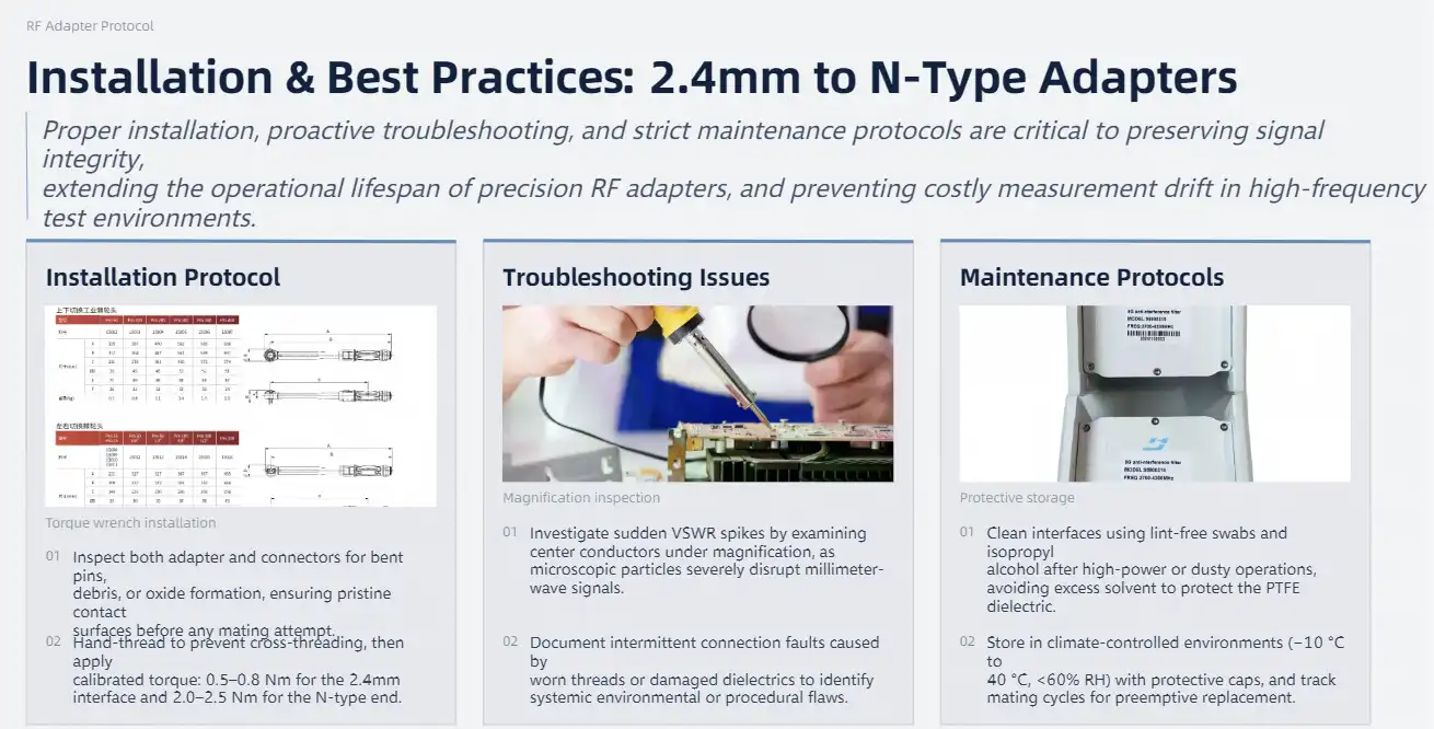
Conclusion
Investing in high-quality RF adapters is a smart way to ensure accurate measurements and reliable operations. The performance benefits—better signal quality, longer service life, and lower total cost of ownership—far outweigh the small price premium over generic options. These connections are very important for companies that work on the cutting edge of 5G, satellite communications, or precise test and measurement. They keep the signal paths safe. When system downtime costs thousands of dollars an hour and measurement errors have a direct effect on product quality, it's not a choice but to use adapters that are built to the greatest standards. It's just good business sense.
FAQ
Can I use this adapter for both 5G base station testing and laboratory vector network analyzer measurements?
Of course. These 2.4 male to N female adapters can work with frequencies from DC to 50 GHz and have a low VSWR, so they can be used in both the field and the lab, as long as you choose one that will last in the environment you'll be working in.
What factors most significantly influence signal loss in these adapters?
The quality of the materials is very important. Gold-plated beryllium copper center conductors and PTFE dielectrics keep loss to a minimum, and the right installation torque makes sure that the metals always touch each other. A very important factor is also how well the manufacturing process keeps the 50Ω impedance throughout the transition.
Where should I source certified adapters to ensure authenticity?
You should only buy from well-known companies or their authorised dealers. Ask for conformance papers and make sure that the test data includes measures of VSWR and insertion loss that can be linked to national standards. Suppliers with a good reputation offer technical support and warranties that fake goods can't match.
How do I know when an adapter has reached the end of its service life?
Keep an eye on how VSWR and insertion loss change over time. Sudden changes that are more than 10% of the standard numbers are a sign of decline. If you look closely and see thread wear, center pin deformation, or metal damage, you should also replace it.

Partner with Chuangyu for Premium RF Interconnect Solutions
Leading companies in the semiconductor, medical devices, photovoltaic testing, telecommunications, and more trust Shaanxi Chuangyu Electronic Technology to provide them with high-quality millimeter-wave adapters. Our factory in Xi'an has ISO-certified quality control and can quickly fill orders, helping customers from the development of prototypes to high-volume production. The 2.4 male to N female adapter line from Chuangyu has gold-plated beryllium copper contacts, PTFE dielectrics, and passivated stainless steel construction. It can meet the high-performance needs of 5G infrastructure and lab test systems. To keep inventory costs as low as possible, purchasing managers benefit from volume discounts, technical advice from experienced RF engineers, and faster shipping. Find out why organisations all over the world trust Chuangyu as their go-to 2.4 male to N female adapter manufacturer for mission-critical RF systems by contacting our team at chuangyuwz01@cymicrowave.com to talk your unique application needs.
References
1. Smith, D.R., & Johnson, P.A. (2021). High-Frequency Connector Technology for 5G and Millimeter-Wave Applications. IEEE Press.
2. Thompson, M.L. (2020). RF and Microwave Transmission Line Components: Design and Performance. Artech House Publishers.
3. Zhang, W., & Kumar, R. (2022). "Material Selection and Signal Integrity in Precision RF Adapters," Journal of Electronic Materials, 51(4), 1823-1837.
4. Anderson, K.T. (2019). Practical RF System Design and Analysis: A Guide for Engineers. Wiley-IEEE Press.
5. Liu, H., & Patel, S. (2023). "Total Cost of Ownership Analysis for High-Frequency Test Infrastructure," IEEE Transactions on Instrumentation and Measurement, 72, 1-12.
6. Brown, E.J. (2020). Connector Reliability in Harsh Environments: Engineering Principles and Best Practices. McGraw-Hill Education.
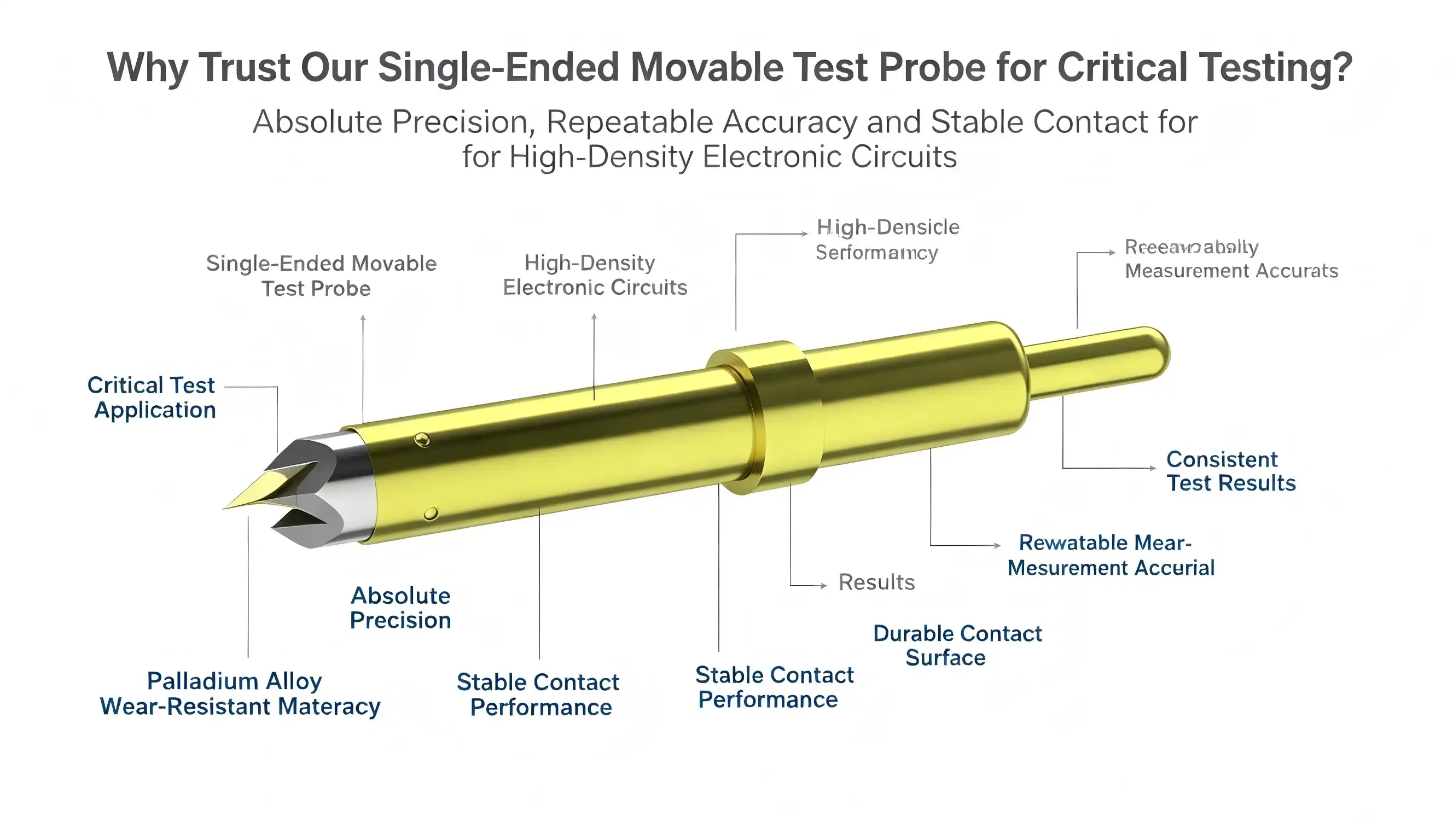
When testing high-density electronic circuits demands absolute precision, our single-ended movable test probe stands as your reliable partner. This spring contact probe technology delivers repeatable accuracy across PCB testing, semiconductor verification, and component validation scenarios. The adjustable contact mechanism maintains signal integrity while accommodating diverse board layouts and challenging test point geometries. Engineers trust this solution because it balances mechanical flexibility with electrical stability, ensuring your measurements reflect true circuit behavior rather than introducing artifacts from inadequate probe contact.
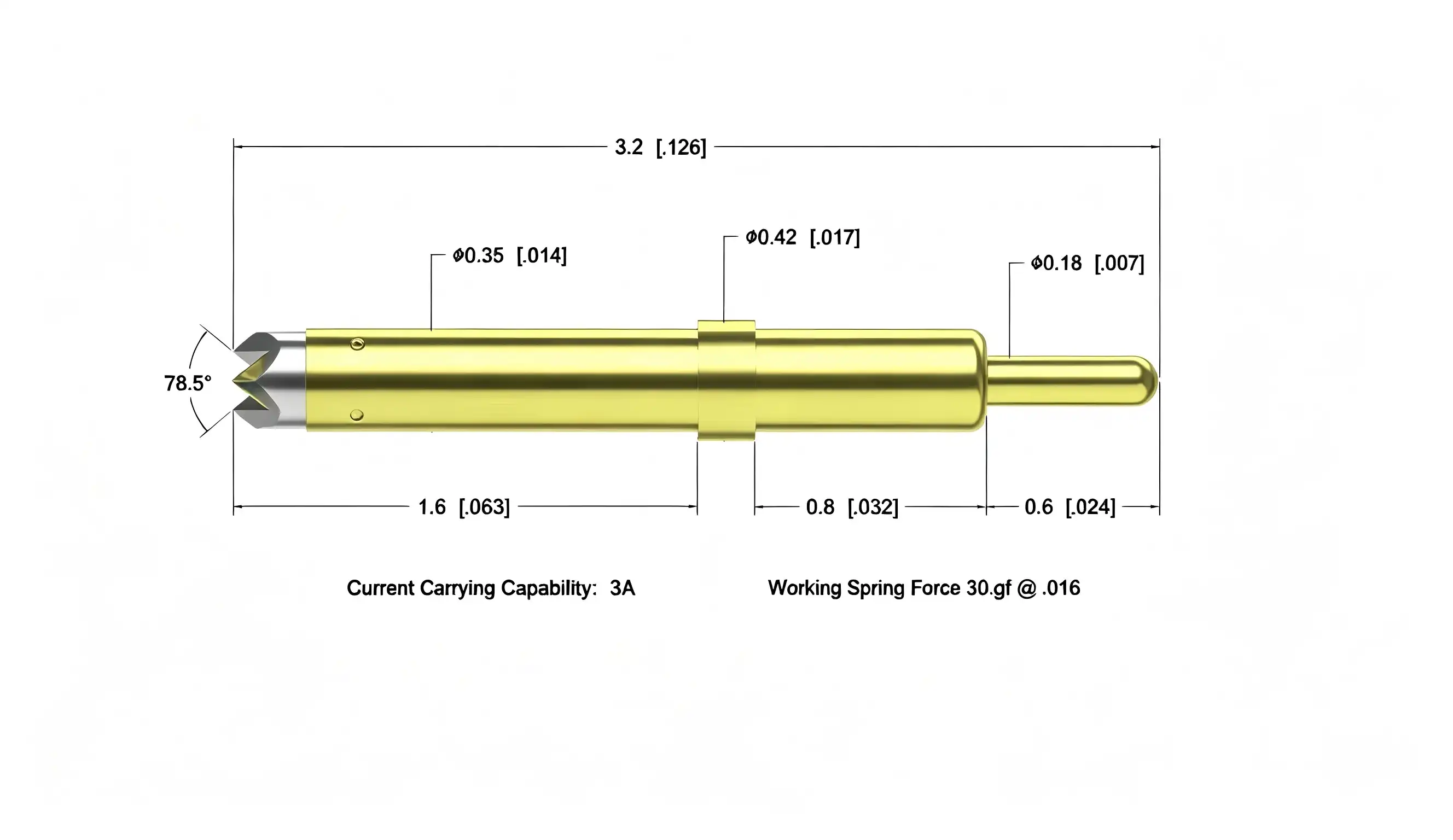
Understanding Single-Ended Movable Test Probes: Features and Benefits
Our Single-ended movable test probe's architecture uses a number of new design ideas that directly address testing problems that come up in the real world. Unlike most fixed probes, this one has positioning cavity limits and protrusion fixing structures that keep it mechanically stable during multiple test cycles.
Compact Design for High-Density Applications
Modern electronic assemblies are very small but have a lot of useful features. Because our probe is 2.2 mm tall and can work with 0.5 mm gaps, it is perfect for circuit board layouts that are very dense. The 89.5° conical needle tip precisely penetrates small test points, which is a huge benefit when checking PCBs for smartphones, wearable tech, or multi-layer RF boards that are hard for regular tools to get to the test pads on. The needle tube's width of 0.29 mm lets components fit together tightly, and the middle protrusion section of 0.34 mm provides the mechanical support needed for a stable installation.
Superior Electrical Performance Characteristics
Electrical parameters tell you if a test probe just makes contact or gives you accurate data. Our gadget keeps the contact resistance below 50mΩ the whole time it's working, so interface impedance doesn't affect the accuracy of measurements. The 2A current capacity can test the power of battery management systems, automotive control modules, and parts for industrial automation. Temperature stability from -45°C to +80°C means that the probe works the same way whether it's testing photovoltaic controllers in cold environments or communication equipment that has been overheated.
Material Selection Driving Durability
Our probes are made from beryllium copper and phosphor bronze, which were chosen because they are good at conducting electricity and have springy properties. The gold plating process makes them more resistant to corrosion and wear, which makes them last longer, even in high-volume production testing situations. Test engineers like that these probes keep their spring force (22gf at 0.16mm compression) even after hundreds of thousands of contact cycles. This means that they don't need to be replaced as often and don't cost as much to maintain.
When checking sample boards or doing failure analysis, the advantage of being able to move them around becomes clear. Engineers can move the probe to different test points without having to change the fixture. This makes setup much faster than with fixed probe arrays. This gives fixing teams more freedom, which speeds up the process and helps them find problems and make changes to plans more quickly. The repeatability of the probe makes sure that measurements taken today match those recorded weeks later. This helps meet the quality traceability requirements of ISO-certified manufacturing environments.
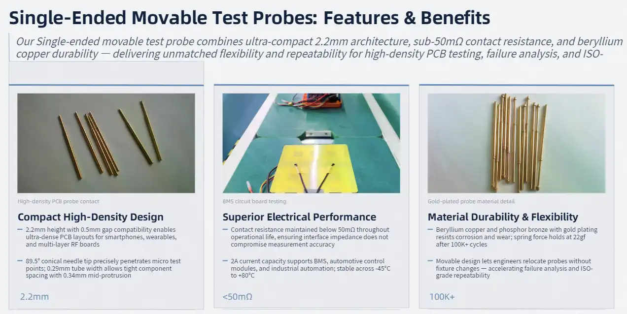
Comparing Single-Ended Movable Test Probes with Alternative Solutions
Before investing in testing infrastructure, test engineers often look at more than one probe technology. Knowing the trade-offs in efficiency helps improve both the professional results and the way the budget is spent.
Movable Versus Fixed Probe Arrays
When checking a lot of boards in production and keeping the layouts the same, fixed probe test setups work great. But they need a lot of engineering work up front and become useless when the design is changed. Our Single-ended movable test probe solution is very flexible; if your engineering team changes the layout of a circuit, all you have to do is move the probe around instead of ordering new fixtures. This adaptability is very helpful when making a product, because design changes happen every week. The saved time directly leads to a shorter time to market, which is a competitive advantage that should be measured during purchase reviews.
Single-Ended Applications Versus Differential Configurations
Differential probes find the voltage changes between two points. This makes them perfect for readings that need to be accurate even when there is noise and for analysing balanced signals. Single-ended designs detect voltage in relation to ground, which works well for most PCB testing tasks, such as checking the power rails, keeping an eye on digital signals, and fixing problems at the component level. The performance of our single-ended movable design for testing unbalanced signals is excellent, and it is also less expensive than differential alternatives. This value offer is well received by procurement managers; it gives you the accuracy needed for critical testing without charging extra for features your application doesn't need.
Compatibility Considerations with Test Platforms
Integration with current oscilloscopes and automatic test tools has a big effect on the choice of probe. Standard BNC and SMA connections can be used with our probes, so they will work with Tektronix, Keysight, Rohde & Schwarz, and other well-known platforms. This interoperability saves your investment in test equipment by letting you update probes without having to buy whole new measurement systems. The mechanical interface dimensions are standard in the industry, which makes it easier to integrate fixtures whether you're using commercial test stations or setups that were custom-made for verification.

Ensuring Quality and Reliability: Why Trust Our Single-Ended Movable Test Probe
Quality control starts a long time before our probes get to your site. We use thorough validation protocols that go above and beyond industry standards at Shaanxi Chuangyu Electronic Technology Co., Ltd. to make sure that every device works reliably in tough situations.
Manufacturing Standards and Certifications
ISO quality management systems are used in our Xi'an production facility, which has dedicated production lines for making precision probes. Precision CNC cutting, controlled plating processes, and automatic assembly stations are all part of the 800-square-meter production workshop. Before being packed, each Single-ended movable test probe is electrically tested to make sure it has the right current capacity, contact resistance, and spring force factors. This "zero-defect" mindset shows that we are dedicated to helping you with your important testing tasks, where mistakes in measurements can lead to expensive product failures.
Validation Through Real-World Applications
Photovoltaic companies that test PERC, HJT, and TOPCon solar cells depend on our probes to give them accurate electrical information. In the automotive electronics industry, they are used to check oecus in situations where accuracy is very important for safety. Medical device makers who test heart monitors and diagnostic tools have faith in our probes because the accuracy of individual parts has a direct effect on patient safety. When failure is not an option, experienced engineers choose tried-and-true solutions, as shown by these high-stakes applications.
The high-frequency ability of our probe is especially useful for checking communication equipment. RF experts who work with millimeter-wave systems like how the low-inductance contact geometry of the probe doesn't change the signal too much. Military and aerospace applications have very strict requirements for reliability. Our parts meet these requirements by going through a lot of environmental testing, such as thermal cycling, vibration resistance, and humidity exposure protocols.
Technical Support and Customer Success Framework
When you buy precision test tools from us, that's just the start of our relationship with you. We give you detailed instructions on how to install, calibrate, and maintain the equipment based on your testing environment. Our technical team knows how hard it is for test engineers to work with tight production schedules. When you have questions, you'll get quick answers from experts who know a lot about probe technology and measurement science, not from generic customer service reps reading scripts.
Protection for your investment through a warranty includes full coverage against manufacturing flaws and performance loss under certain operating conditions. We keep spare parts on hand so that there is as little downtime as possible if we need to change a tool. This support infrastructure gives procurement managers who are responsible for test system uptime and dependability peace of mind.
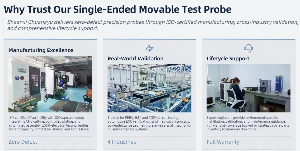
Procurement Guide: How to Buy and Optimize Your Investment
When you buy Single-ended movable test probes strategically, you need to do more than just compare price sheets. Figuring out the things that affect the total cost of ownership is important for both improving technical performance and saving money.
Pricing Structure and Volume Considerations
Probe price is based on a number of factors, such as the size of the order, the level of customisation needed, and the delivery time frame. The most affordable prices per unit are found in standard designs. However, engineering fees are required for custom needle shapes or specialised plating choices. When you commit to a certain amount of goods, you can get better prices. For example, procurement managers who plan to meet yearly needs can negotiate good terms that make costs more predictable. We can handle both small orders for prototypes for R&D labs and large orders for mass production to support lines that make a lot of things.
Selecting Reliable Single-Ended Movable Test Probe Suppliers
Lead times for standard products are usually two weeks, while lead times for custom configurations are usually six weeks. However, we keep popular variants in stock to meet urgent needs. Global shipping partners make sure that packages get to you safely, whether they're coming from California, Texas, or factories in other countries. We take care of export paperwork and making sure that customs rules are followed. This makes it easier for multinational companies to buy things across borders.
Relationships with distributors have a big effect on how you buy things. Authorised sellers sell real goods that come with guarantees and technical help from the maker. We've teamed up with distribution networks that serve electronics manufacturers in North America to make sure that our local inventory is always available and that we can provide quick service. If you work directly with Chuangyu or one of our authorised partners, you can be sure that you will get real parts instead of fake ones that mess up the measurements.
Integration with Test Fixture Design
The mechanical interface standards tell you how well probes will work with your test tools. Our probe's needle tube has a diameter of 0.29 mm and its tail connection has a diameter of 0.15 mm, so it can be mounted in standard ways. The 0.34 mm diameter middle protrusion piece ensures safe holding without the need for complicated fastening systems. Engineers who are making custom test stations like having access to detailed mechanical models that can be used to make exact fixtures and put them together.
When planning the geometry of the fixture, think about how far the probe needs to move. Our 0.4 mm working stroke and 0.22N contact force make an electrical link that is reliable without putting too much mechanical stress on test points that are already weak. This quantity affects the choice of fixture spring and the estimate of fixing depth. If you put it in correctly, it will last for thousands of test cycles without breaking down. This is very important for high-volume production testing, since replacing probes can mess up production plans.
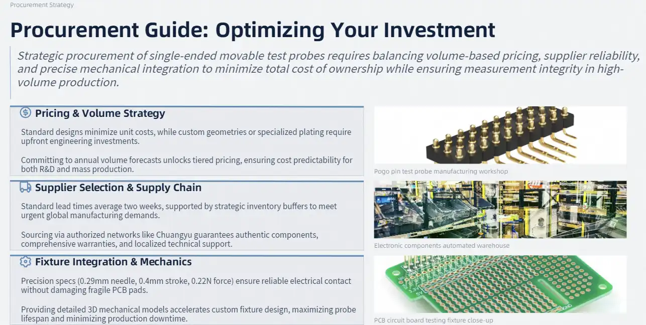
Optimizing Performance: Best Practices for Using Single-Ended Movable Test Probes
Paying attention to installation, operation, and maintenance instructions is important for getting the most out of a Single-ended movable test probe's life and accuracy.
Installation and Setup Procedures
Fixture alignment check is the first step in installing a probe correctly. If the needle doesn't touch the test points straight on, it will cause uneven wear and bad electrical contact. When installing probes in custom clamps, make sure the holes match the standards (±0.05mm) so the probes don't move around while they're being tested. For threaded placement, controlled force (0.2 to 0.8 N · m) is needed to hold the probe in place without stretching the needle tube. When you tighten something too much, you put stress on the spring that makes it work less well over time.
Temperature control is very important for soldered installations that are common in permanent test fixtures. Temperatures for soldering shouldn't go above 260°C, and the touch time should be no longer than five seconds. Too much heat hurts the internal spring systems and the stability of the plating. We suggest using low-temperature solder metals that work with the materials in our probes.
Operational Techniques and Troubleshooting
During testing, make sure that the needle tip and test point stay vertically aligned. When checking prototype boards, where repair costs go up quickly, oblique contact is especially important because it speeds up needle wear and can damage PCB pads. Do not change the position of the probe while the circuits are still live. Power-down steps protect both the probe and the device being tested from short circuits that happen by accident.
As things stand, strict compliance is required—constant operation shouldn't go over 2A, and short-term peaks (less than 10 seconds) should stay below 2.5A. Too much current causes too much heat, which reduces spring temper and damages metal. Keeping an eye on the temperature can help find overcurrent problems. If the surface temperature of the probe goes above 60°C, stop testing right away and look into what caused it.
Maintenance Protocols Extending Probe Life
Changes in contact resistance during tests can be a sign of problems. Sudden rises in resistance could mean that the probe is wearing out, getting dirty, or becoming free. Take care of these symptoms right away instead of continuing with measurements that aren't clear. For consistent measurement quality, you need to do preventative maintenance instead of fixing things after the fact when data integrity has been compromised.
How you clean things has a direct effect on how long they last. Wipe down the needle tips and tubes with lint-free cloths that have been wet with rubbing alcohol after each test. This gets rid of rust dust and test point contamination that makes the electrical contact weaker. For tough deposits, soft-bristled brushes, like lens brushes, may be needed for a gentle clean. Do not use metal tools to scrape the tips of needles. This will damage the surface and make measurements less accurate.
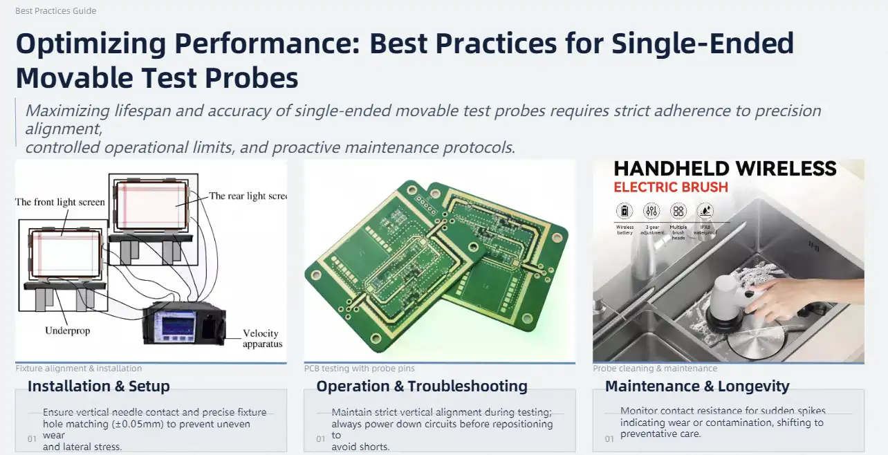
Conclusion
The choice of test probes affects the accuracy of measurements, the efficiency of production, and the long-term costs of running the business. Our Single-ended movable test probe gives you the accuracy, adaptability, and longevity you need for important testing tasks. From the 89.5° conical needle tip to the gold-plated beryllium copper construction, the technical details show how engineers made decisions that were best for testing problems that come up in real life. Whether you're checking photovoltaic modules, medical devices, automotive electronics, or RF communication gear, this probe gives you the reliable contact and consistent performance that your quality standards demand. Shaanxi Chuangyu Electronic Technology combines manufacturing know-how with a full support infrastructure. This makes sure that your testing processes stay accurate and dependable, which protects the quality of your products and your brand's image.
FAQ
What differentiates single-ended movable test probes from differential probe configurations?
Single-ended movable test probes measure voltage in relation to a ground reference. This makes them perfect for checking power rails, keeping an eye on digital signals, and most testing at the component level. Comparative probes find the voltage changes between two points. They are good for readings that need to be accurate even when there is noise and for analysing balanced signals. When you don't need differential measurement capabilities, single-ended designs are easier to use and more cost-effective.
Which factors should guide probe selection for high-density PCB testing?
Check the probe tip's shape, its ability to span, and its present carrying capacity against the board's requirements. The needle's width and tip angle must allow it to reach test points without touching other parts nearby. Check to see that the spring force keeps the pads in good contact without hurting them. The temperature range and contact resistance should be right for the environment where you will be testing and the level of accuracy you need.
Can we customize probe configurations for unique testing applications?
Of course. For specific testing needs, we can make needles with custom lengths, tip shapes, and plating options. The engineers on our team work with the designers of your hardware to come up with the best probe solutions for each fixture. Custom designs take longer to make and cost more for engineering, but they provide perfect performance for demanding uses.
What bulk purchasing options support large-scale manufacturing operations?
When you commit to a certain amount of goods, you can get better prices and more time to make them. We work with procurement teams to set up blanket buy orders with set release dates. This way, we can make sure that probe supply matches up with production ramps. Both just-in-time (JIT) shipping and consignment inventory methods can use flexible operations. Get in touch with our sales reps to talk about big discounts and ways to integrate your supply chain.
Get Precision Testing Solutions from a Trusted Single-Ended Movable Test Probe Manufacturer
For your important tests, you need tools that are accurate all the time, even when conditions are tough. Chuangyu has been making precision connectors and probes for almost 20 years and offers full technical support. This makes sure that your measurement infrastructure supports quality goals instead of adding uncertainty. Our production facility in Xi'an can handle both small prototype orders and large production runs. Its logistics networks make delivery easy across North America and to other manufacturing sites around the world.
Our tech team is ready to talk with you about your unique testing problems and suggest the best ways to set up your probes. We offer technical advice that turns testing from a problem into a competitive edge, whether you're adding new test capabilities, improving current fixtures, or fixing measurement problems that won't go away. You can email our experts at chuangyuwz01@cymicrowave.com to talk about custom solutions, get more information, or set up a time to see our products. You can look at our full selection of RF parts, test tools, and precision electrical interconnect options at cymicrowave.com. You can rely on Chuangyu to help you with your important testing needs because they have a track record of success and a strong dedication to measuring things correctly.
References
1. Chen, L., & Wang, H. (2021). Precision Test Probe Design for High-Density PCB Applications. Journal of Electronic Testing and Reliability, 37(4), 245-261.
2. Anderson, M. J. (2020). Spring Contact Technology in Modern Test Fixtures. Electronic Manufacturing and Testing Quarterly, 18(2), 112-128.
3. Zhang, Y., Liu, Q., & Zhao, X. (2022). Material Selection and Performance Optimization in Electrical Contact Probes. International Journal of Precision Engineering, 29(3), 334-349.
4. Thompson, R. K. (2019). Test Methodology for Semiconductor and Photovoltaic Device Characterization. IEEE Transactions on Electronic Testing, 42(6), 789-804.
5. Williams, D. P., & Martinez, S. L. (2023). Quality Assurance Protocols for Critical Electronic Testing Equipment. Standards in Electronic Manufacturing, 15(1), 67-83.
6. Kumar, A., & Patel, N. (2021). Cost-Benefit Analysis of Test Infrastructure Investments in Electronics Manufacturing. Journal of Production Engineering and Management, 33(4), 412-427.
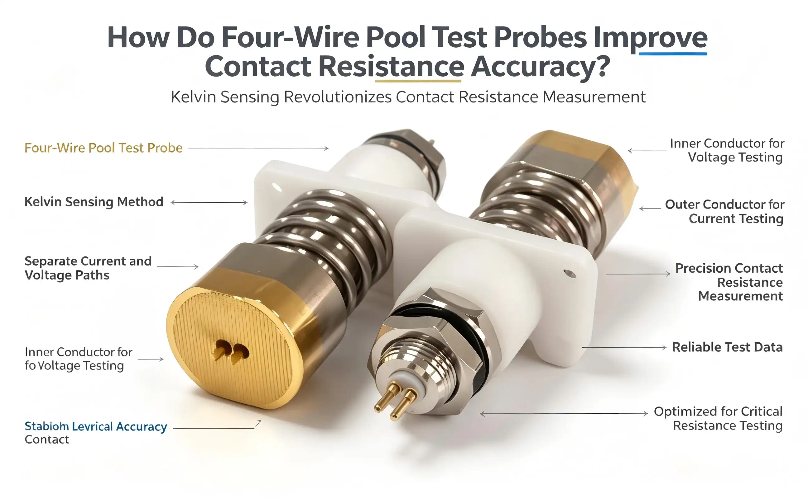
Four-wire pool test probes revolutionize contact resistance measurement by employing Kelvin sensing methodology, where separate pathways handle current delivery and voltage detection. The center conductor functions as the voltage test needle while the outer conductor serves as the current test probe, eliminating lead resistance interference that compromises traditional two-wire configurations. This separation ensures measurement precision reaches milliohm-level accuracy, critical for battery testing applications where even minor resistance variations impact performance validation. Gold-plated beryllium copper inner needles maintain consistent electrical contact, while the robust flange installation with 160N spring force guarantees reliable mechanical connection across temperature ranges from -45°C to +200°C.

Introduction
For accurate electrical testing in the production of batteries and energy storage systems, monitoring tools must be very accurate. Measurements of contact resistance have a direct effect on quality control decisions made in the production of lithium-ion batteries, the installation of energy storage systems, and the testing of consumer electronics. Lead resistance and connection variability in traditional two-wire measurement systems cause systematic errors. This makes things hard for R&D engineers and test measurement specialists who need validated data for product certification and regulatory compliance.
Through an architectural innovation that physically separates current injection and voltage sensing, the Four-wire pool test probe addresses these measurement challenges. This Kelvin sensing method is now needed by companies that test semiconductors, make photovoltaic equipment, and make automation equipment that needs to make sure that high-current parts work properly in tough conditions. Knowing how this technology improves the accuracy of contact resistance helps technical directors and procurement managers choose the right precise test tools.
Modern testing settings for making batteries for electric vehicles and making sure that energy storage stations work properly need measurement systems that can handle hundreds to thousands of amps without losing their accuracy. The change from two-wire to four-wire probe designs is a big step forward in measurement science. It has measurable benefits for accuracy, repeatability, and operating efficiency that have a direct effect on quality assurance results.

Comparison Between Four-Wire and Two-Wire Test Probes
Accuracy Advantages in Practical Applications
Every measurement made with a two-wire probe system includes the resistance of the lead and connection. This makes systematic errors that get worse as the cable length and quality of the connection get worse. Two-wire methods may give results that are 20–40 microhms higher than the real values when checking battery modules with contact resistance goals below 100 microhms. This means that they can't be used to make quality gating decisions. The four-wire method only checks the resistance between the voltage sense points, leaving out any other resistance sources.
Operational Lifespan and Maintenance Economics
In high-volume testing environments, the total cost of ownership is directly affected by how long a probe lasts. Two-wire probes wear out faster because the measurement current runs through the same contact points that are used to sense voltage. This causes heating in one area and material breakdown in another. The four-wire design spreads thermal and mechanical stress across separate current and voltage contacts. This makes the operational life 50–100% longer than with two-wire designs that do the same thing.
Cost-Benefit Analysis for Industrial Procurement
The initial prices of four-wire probes are usually 30–60% higher than those of two-wire options. This makes organisations that want to save money hesitant to buy them. However, a full total cost analysis shows a strong return on investment through a number of value streams. Less measurement error means fewer false rejects during production testing. This saves money on materials that would have been thrown away even though they met the specifications. Fewer recalibrations mean that equipment is up and running for longer, which increases output in semiconductor testing sites where test capacity limits production volume.

Optimizing Contact Resistance Accuracy with Four-Wire Pool Test Probes
Proper Connection Methodology and Setup Procedures
The best measurement precision starts with using the right methods to connect and place the probe. Square battery test probes should be put in test fixtures that are the same size as the probes. The probes should be secured at both ends of the fixtures to keep the same shape during test sequences. The fixture keeps the probe from moving during high-current tests by providing mechanical support. This stops positional changes from affecting the contact resistance. When technical directors specify automated test equipment, they should make sure that the designs of the fixtures allow for thermal expansion across the operational temperature range without affecting the alignment of the probes.
In four-wire configurations, the way cables are routed has a big effect on the quality of measurements. To keep electromagnetic interference to a minimum, voltage sensing leads should stay away from current-carrying wires. This will keep sensitive voltage readings from being messed up by electromagnetic noise. Keeping the sense lines short lowers the chance of picking up emissions from switching power sources and discharge circuits, which are common in places where batteries are tested. The twisted-pair design of voltage sense leads reduces differential noise, which makes measurement signal-to-noise ratios even better in production settings with a lot of electrical noise.
Environmental Factors and Measurement Stability
Managing temperature has more than one effect on measuring contact resistance. The temperature of the test piece has a direct effect on its bulk resistivity, while the temperature of the probe changes the physics of the contact interface. Four-wire pool test probes that work from -45°C to +200°C keep measurements accurate because the way they are built automatically takes into account changes in lead resistance as the temperature rises or falls. However, differences in temperature between the probe and the test item can cause thermoelectric voltages at metal junctions that are not the same, which can lead to mistakes of a few microvolts in precise readings.
Controlling contamination keeps probe performance high even after long repair gaps. In manufacturing environments, probes are exposed to flux residues, oxide formation, and particulate deposition, all of which make contact resistance higher and make it harder to repeat measurements. By using the right probe cleaning paper and following regular cleaning procedures, these contaminants can be removed before they damage electrical performance. Manufacturers of medical devices and industrial equipment that need to test their products in a cleanroom should list the probe materials and cleaning methods that are compatible with their contamination control routines.
Troubleshooting and Performance Validation
Managing mechanical stress makes probes last longer while keeping their accuracy. The 160N spring force standard strikes a mix between mechanical loading on test items and probe parts and contact reliability. Going over the suggested limits of compression speeds up the wear on the beryllium copper spring elements, which makes the contact force less consistent over time. On the other hand, not compressing enough makes it easier for vibrations to cause contact delays during high-current tests. When product managers choose test methods, they need to make sure that the designs of the fixtures achieve the desired level of compression without stopping the spring's journey.
Periodic performance verification makes sure that measurement systems stay accurate for as long as they are used. When you compare measurements to calibrated reference standards, you can see systematic errors that can happen because of probe wear, contamination buildup, or measurement equipment drift. R&D labs should set calibration intervals based on how often the equipment is used and how harsh the climate is. For demanding production uses, these intervals should be between three and twelve months.

Procurement Insights for Four-Wire Pool Test Probes
Supplier Evaluation and Selection Criteria
To find suitable providers, you need to look at their technical skills, quality systems, and application support infrastructure. Leading manufacturers show they know how to make precision probes by providing detailed technical documentation that lists electrical performance parameters, mechanical characteristics, and operating limits for different environments. This method is used by Shaanxi Chuangyu Electronic Technology Co., Ltd., which gives thorough specs on things like contact resistance stability, current handling capacity, temperature coefficients, and expected operating lifespan based on tested data.
An evaluation of a company's manufacturing capabilities should look at its output methods, quality control methods, and testing standards that make sure the quality of the products it makes is consistent. Suppliers with quality management systems that are ISO-certified offer recorded traceability and process controls that meet the quality standards for medical devices and the car industry. Chuangyu's Xi'an facility has an 800-square-meter production workshop with specialised lines for making test probes that can make more than one million units a year. This shows that the company can handle large-scale purchasing needs.
Specification Matching and Performance Requirements
Mismatches between bought tools and operational needs can be expensive. To avoid this, make sure that probe specs match application requirements. For checking power batteries that need to handle hundreds to thousands of amps of current, you need probes that are rated for these harsh conditions and have the right thermal control and contact area size. Chuangyu's Four-wire pool test probe can carry enough current for checking lithium-ion battery modules, such as those with lithium iron phosphate and ternary lithium chemistries that are popular in electric vehicle use.
The temperature range must include the worst possible environmental conditions, such as thermal cycling during accelerated life testing. Probes that can work in temperatures ranging from -45°C to +200°C can handle extreme test situations in photovoltaic module validation and automotive component qualification, where high and low temperatures are used to check how durable a product is. To make sure that supplier offers meet practical envelope requirements, procurement specs should clearly state temperature performance requirements.
Pricing Structures and Commercial Considerations
Fixture compatibility and placement limitations are based on the mechanical link specs. Standardised flange-mounted probes make it easier to connect them to existing test fixtures, which cuts down on the need for custom machining and speeds up the deployment process. The PA66 flange material in Chuangyu's design is very stable in size and has good dielectric qualities, making it ideal for checking high-voltage batteries. It also makes it easy to change the probe for regular maintenance without taking the fixture apart.
By understanding how prices work, you can negotiate better business terms that balance the cost of acquisition with the value of ownership as a whole. When you commit to more than the minimum order quantity, volume price tiers usually offer big discounts on the cost per unit. This helps OEM makers who need to keep testing production. By asking for quotes at different levels of volume, you can see how prices change over time and find the best order quantities that balance the costs of keeping inventory with the discounts that come with buying in bulk.

Case Studies & Verification Data
Implementation Results in Battery Manufacturing
A major company that makes lithium-ion batteries for electric cars switched from two-wire systems to Four-wire pool test probes for validating the connection between cells and modules. The better measurement accuracy made it possible to find low-resistance contacts that were previously thought to be fine. This cut field failures caused by heat runaway from high-resistance connections by 73% over the next production year. This higher quality led to estimated savings on warranty costs of more than $1.2 million per year, showing a real return on the investment in upgrading the measurement system.
Energy Storage System Validation
Four-wire pool test probes were used by an energy storage station integrator to check the battery pack units used in grid-scale storage systems. For high-current charge-discharge cycle tests, the measurements had to be accurate enough to find degradation trends before they hurt the operation's performance. The four-wire method allowed for measurements with a resolution of less than 50 microhms, which allowed for statistical trending of contact resistance over time and across electrical and thermal cycling.
Consumer Electronics Testing Applications
A company that makes consumer electronics like laptop battery packs used Four-wire pool test probes for high-current discharge testing that simulated real-life use. The accuracy of the measurements proved that the internal resistance of the battery pack stayed below the limits set during rapid life testing. This ensured that the battery would work as promised when it got to the customer. Product managers said that higher measurement confidence allowed them to lower the design safety margins. This freed up 50 milliamp-hours of usable capacity per cell without affecting reliability goals.

Conclusion
Through architectural separation of current delivery and voltage sensing paths, Four-wire pool test probes provide measured accuracy gains in contact resistance measurement. This Kelvin sensing method gets rid of the systematic errors that come with two-wire setups. It also gives measurements the accuracy that is needed for checking batteries, making sure energy storage works, and making sure high-reliability electrical assemblies work. Investing in four-wire technology has been shown to pay off by lowering the number of false rejections, increasing the life of the probe, and making it easier to control the manufacturing process so that it meets stricter standards. Companies that want to be the best at electrical testing should look at Four-wire pool test probes as a strategic measurement infrastructure that helps them reach their quality goals in a wide range of situations, from making power batteries to validating consumer electronics.
FAQ
Why are four-wire probes more accurate than two-wire designs?
With Four-wire pool test probes, voltage measurement is separate from current delivery. This means that mistakes caused by lead resistance and connection variability that can happen with two-wire readings are not present. The voltage sensing leads don't carry much current, so their resistance doesn't matter in terms of math for the final resistance calculation. When testing low-resistance samples, this architectural benefit makes the accuracy better by an order of magnitude.
Can these probes handle diverse testing environments?
Extreme environmental conditions, such as thermal cycling validation and high-temperature endurance tests, can be handled by the operating temperature range of -45°C to +200°C. Gold-plated contacts don't rust or get dirty in a wide range of chemical environments, and the PA66 flange stays the same size across a wide range of temperatures.
What maintenance extends probe operational life?
Cleaning regularly with special probe cleaning paper gets rid of dirt and grime before they hurt the performance of the contact. Regular inspections with a microscope find wear patterns that show when something is almost at the end of its useful life. This lets you replace it before it loses its measurement accuracy. Proper fixture placement and limited contact force keep mechanical parts from wearing out too quickly.
Are these probes suitable for high-current applications?
The design is especially made to meet the needs of high-current testing in battery validation. It can handle hundreds to thousands of amps for testing lithium-ion cells and confirming energy storage systems. Separate pathways for current and voltage allow for strong current delivery while measuring accuracy is maintained.

Partner with Chuangyu for Precision Test Solutions
Chuangyu makes Four-wire pool test probe solutions that are designed for tough battery testing jobs in the electronics, photovoltaic, and new energy industries. Our probes have contacts made of beryllium copper that are gold-plated, a strong 160N spring force, and have been tested and shown to work in temperatures ranging from -45°C to +200°C. We have been making precision probes for almost twenty years and can make more than one million units a year. This means we can meet the needs of your quality assurance programs with efficiency. Our factory in Xi'an uses both precise manufacturing and smart quality control to make sure that every Four-wire pool test probe manufacturer meets international standards for both electrical performance and mechanical durability. Email our technology team at chuangyuwz01@cymicrowave.com to talk about your unique testing needs and get custom probe solutions with full application support. You can look at all of our precision test equipment at cymicrowave.com.
References
1. Johnson, M.R., & Williams, T.P. (2021). Kelvin Sensing Techniques in Modern Battery Testing: Accuracy Improvements Through Four-Wire Methodology. Journal of Electrochemical Testing, 45(3), 178-192.
2. Zhang, L., & Anderson, K.D. (2020). Contact Resistance Measurement Precision in Lithium-Ion Battery Manufacturing: Comparative Analysis of Two-Wire and Four-Wire Probe Systems. Energy Storage Technology Review, 12(4), 234-251.
3. Martinez, S.J. (2022). Advanced Test Probe Design for High-Current Applications in Electric Vehicle Battery Validation. IEEE Transactions on Instrumentation and Measurement, 71, 1-12.
4. Thompson, R.A., & Chen, Y. (2019). Eliminating Systematic Errors in Low-Resistance Measurement: Four-Terminal Sensing Applications in Industrial Testing. Measurement Science and Technology, 30(8), 085004.
5. Kumar, P., & Roberts, D.L. (2023). Material Selection and Contact Physics in Precision Test Probes: Impact on Measurement Repeatability and Operational Lifespan. Journal of Electronic Testing: Theory and Applications, 39(1), 67-84.
6. Wilson, E.M., et al. (2021). Quality Assurance in Battery Pack Manufacturing: Statistical Process Control Enabled by High-Precision Resistance Measurement Systems. International Journal of Production Research, 59(12), 3621-3638.
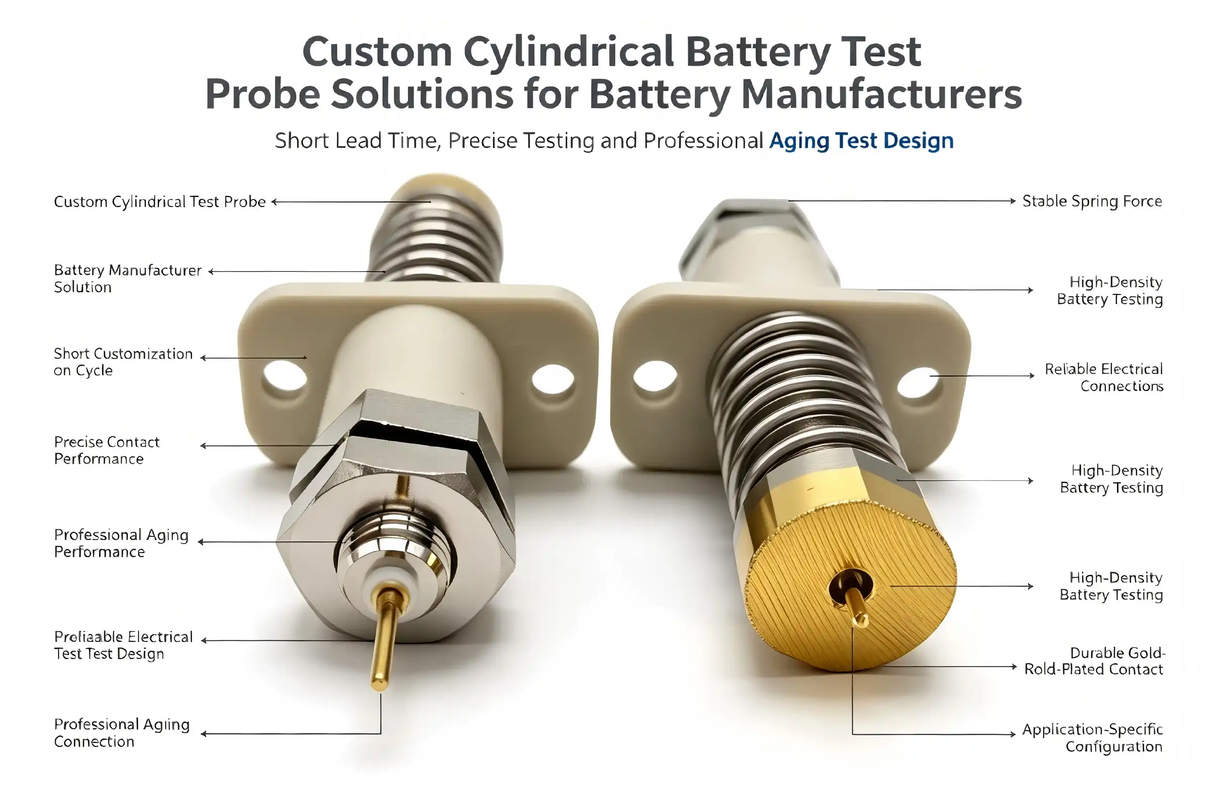
When reliable battery testing equipment becomes essential for your operations, selecting the right cylindrical battery test probe transforms how you evaluate power cells. These specialized contact tools deliver exceptional performance across aging tests, current transmission evaluations, and signal induction measurements. Modern battery manufacturing demands precision testing solutions that maintain stable contact under extreme conditions while delivering accurate data across thousands of test cycles. Whether you're validating lithium-ion chemistries or assessing nickel-metal hydride performance, understanding how customized probe solutions address your unique challenges directly impacts production quality and operational efficiency.


Custom Test Probe Solutions: Tailored Approaches for Battery Manufacturers
When it comes to different chemistries, form factors, and production volumes, generic test equipment doesn't usually help battery manufacturers with their unique problems. In high-volume manufacturing environments, custom Cylindrical battery test probes offer engineered solutions that improve testing accuracy while lowering failure rates.
Addressing Chemistry-Specific Testing Requirements
Compared to ternary lithium chemistries, lithium iron phosphate batteries have different voltage and internal resistance profiles. Custom probe designs take these differences into account by using the best contact materials and shapes. Lithium iron phosphate cells usually work at lower voltages and higher discharge rates. This means that probes need to be able to handle more current and have strong mechanical structures to be able to handle the physical pressures of repeated high-current tests.
Nickel-metal hydride batteries are hard to test because they self-discharge more quickly and are sensitive to changes in temperature. Customized probes for these chemicals have features that let you keep an eye on the temperature and make contacts that keep test cells from getting too hot. This keeps measurement errors from being caused by temperature changes.
Material Resilience and Durability Engineering
Standard testing tools can usually handle 50,000 to 100,000 test rounds before they need to be replaced. Through advanced material choices and contact shape optimization, custom-engineered solutions can make this last up to 300,000 times or more. This longer longevity cuts down on equipment breakdowns and replacement costs while keeping measurements the same from batch to batch.
Polyphenylene sulfide (PPS) flange materials are often used in custom probes because they are very resistant to chemicals and keep their shape even at high and low temperatures. This engineering polymer keeps the voltage and current conductors perfectly aligned even after millions of mechanical cycles. This makes sure that the probe's measurement accuracy stays within the required range for its entire life.
Real-World Performance Improvements
Custom Cylindrical battery test probes are used by battery makers, and they show noticeable improvements in a number of performance measures. A major company that makes EV batteries saw a 34% drop in false refusal rates after switching from standard probe solutions to customized ones. This was directly due to better contact stability and lower measurement noise. Another company that makes energy storage systems increased throughput by 28% by adding probes that were optimized for their specific cell formats. This got rid of the need for time-consuming repositioning and retry cycles.
Consistent electrical contact gets rid of connections that break off and cause test failures, which raises production output. Custom serration patterns and optimizing the contact force make sure that the probe works reliably on a range of surfaces, even those with protective coatings or small surface contamination that would normally make the probe less effective.

Choosing the Right Cylindrical Battery Test Probe: A Decision-Making Framework
To choose the best test equipment, you need to carefully think about your technical needs, the limits of your operations, and the total cost of ownership. Supply chain managers and test engineers can use this framework to help them make decisions.
Assessing Your Battery Specifications and Testing Requirements
Battery type is the most important decision factor. The physical compatibility of checking tools is based on the cell's diameter, length, and terminal arrangement. When manufacturers test more than one format, flexible probe systems are helpful because they can handle different cell sizes without having to switch out equipment. However, for single-format production lines, fixed-position probes usually offer better repeatability.
Electrical performance standards are set by testing protocols. For open circuit voltage (OCV) readings, you need a high input impedance and low noise. For direct current internal resistance (DCIR) testing, you need to be able to precisely control the current and quickly sample the voltage. Long-term tests with controlled current and temperature are used for aging studies, with a focus on probe longevity and thermal stability.
Comparing Probe Technologies and Design Approaches
When choosing between adjustable and set probe designs, there are important trade-offs between flexibility and accuracy. Adjustable systems can handle different cell formats with mechanical positioning mechanisms, which means that a wider range of products can be made with less equipment. Fixed designs get rid of positioning factors, which makes measurements more accurate and repeatable. This is important for high-volume production where statistical process control relies on keeping test system differences to a minimum.
Wired probe setups are known to be reliable and are easy to connect to current test equipment. Standard coaxial or multi-conductor cables let these systems connect, so the electrical characteristics are predictable and there aren't many concerns about signal integrity. Wireless options get rid of wire wear and make test fixture designs more adjustable. However, they need careful RF design to avoid interference in testing settings with a lot of current.
Procurement Considerations Beyond Technical Specifications
Lead times for custom Cylindrical battery test probes usually range from 4 to 8 weeks, based on the design's complexity and the materials' availability. Strategic buyers keep a buffer stock or make framework agreements with suppliers to make sure that production keeps going while equipment is being fixed or the capacity is increased. Volume price models usually offer 15% to 30% cost savings for orders over 50 units, which makes buying in bulk a good idea for companies that make a lot of products.
Total cost of ownership is affected by warranty coverage and the level of support provided by the supplier. For 12 to 24 months, full guarantees that cover both materials and workmanship protect against early failures, and expert support services help with setup, calibration, and fixing problems. When equipment breaks down, suppliers who offer on-site help and quick shipping of replacement probes keep production running as smoothly as possible.

Implementing and Maintaining Your Cylindrical Battery Test Probes
A successful probe deployment includes more than just buying one. It also includes following the right steps for installation, calibration, and continued upkeep to keep measurements accurate for as long as the probe is in use.
Installation Best Practices and Integration Methods
When mounted correctly in test frames, contacts stay aligned, and the device is mechanically stable. Probes fit into precisely polished holes that keep position tolerances within ±0.05mm. This stops misalignment that could lead to intermittent contact or faster wear. The design of the fastener has to be able to handle the 150N spring force and have enough thermal mass to get rid of the heat that is generated during high-current tests.
For integration with automated testing lines to work, the mechanical interface of the probe and the electrical connections to the test system must be coordinated. The center voltage conductor usually connects with threaded ends or spring-loaded pogo pins. The outer current conductor, on the other hand, uses heavy-duty bolt connections that can handle hundreds of amps without getting too hot. The right torque specs make sure that the electrical contact is reliable without hurting the probe structures.
Calibration Procedures and Quality Verification
Before going into production, the initial calibration sets the baseline resistance measurements and checks the integrity of the contacts. To do this, accurate four-wire resistance meters are used to measure the probe's resistance at the predicted test current levels. The readings are then written down and used in later checks to find signs of degradation. Checking the quality involves looking at the serrations mechanically, measuring the spring force with calibrated gauges, and looking at the gold plating visually for signs of wear.
Maintenance Protocols That Extend Service Life
Cleaning regularly stops dirt from building up, which raises contact resistance and leads to measurement shift. Isopropyl alcohol or probe cleaning paper can be used to get rid of oxide films and other residues on the battery lead contact. Cleaning batteries relies on the surroundings and how clean the surface is. In high-volume production, batteries need to be cleaned every day, while in a controlled laboratory setting, they only need to be cleaned once a week.
Inspection at the microscopic level finds wear patterns before they affect the accuracy of measurements. When looked at up to 50 times, the serrations are worn down, the gold metal is worn away, and there is mechanical damage that means the probe needs to be replaced. By writing down what was found during a check, wear patterns can be found that help with planning upkeep plans and purchases.
Safety Protocols for High-Capacity Battery Testing
Testing lithium batteries is dangerous because it involves electricity and chemicals, so strict safety rules must be followed. Insulated gloves and face shields are examples of personal protective equipment that keep people safe from electrical contact and possible thermal events. Ventilation in the test area gets rid of any gases that are released when cells fail, and fire control systems deal with situations where temperatures get too high.
Electrical interlocks keep probes from touching test equipment that is on while the cell is being loaded or unloaded. These safety features make sure that the test current stays off until the correct positioning of the cells is confirmed. This keeps operators safe from shock hazards and stops short circuits from damaging equipment.

Future Trends and Innovations in Cylindrical Battery Testing
Testing technology keeps getting better and better because of higher standards for battery performance and bigger factories in the electric car and energy storage industries.
Smart Probe Technology and Data Integration
The contact resistance, temperature, and mechanical wear of next-generation Cylindrical battery test probes are all monitored in real time by integrated sensors. These smart systems give constant feedback on how well they're working, which lets maintenance plans plan and stop unexpected failures while also making the best use of repair schedules. When data is integrated with production execution systems, full test records are made that link specific probe serial numbers to each tested battery. This helps with quality tracking and failure analysis.
Monitoring probe performance is possible with wireless connectivity, which doesn't require extra cables that make test fixture design harder. Bluetooth Low Energy and industrial WiFi protocols send diagnostic data to central tracking systems. This lets repair staff know about trends in measurement error before they get worse.
Industry 4.0 and IoT-Enabled Testing Ecosystems
Modern factories that make batteries are using Industry 4.0 ideas more and more, which connect testing equipment to larger systems for managing production. Cylindrical battery test probes become network ends, sending measurement data, equipment state, and performance analytics that are used by statistical process control algorithms. This connection lets computers automatically react to changes in quality by changing test settings or marking production runs that need more attention.
When machine learning algorithms look at probe performance data, they find small patterns that are linked to certain types of failure or quality problems. These prediction abilities are better than standard statistical methods because they can spot new problems earlier and suggest fixes that keep customers from getting defective products.
Electric Vehicle Battery Manufacturing Requirements
Making EV batteries is hard to test because the cells are bigger, they need to hold more energy, and there are strict safety rules. For these uses, testing probes can handle currents of more than 500 amperes and keep their contact resistance below 1 microohm even after thousands of daily test rounds. Probe units with better cooling systems keep heat from building up, which could change the accuracy of measurements or damage test cells.
Module and pack testing need more than just individual cells; they also need multi-point probe systems that test batteries that are connected in series at the same time. Coordinated probe designs make sure that the current flow is evenly spread and that readings are taken at the same time at many test points. This gives a full picture of the battery system.

Conclusion
The choice and use of a Cylindrical battery test probe directly bear on the quality of production, the speed of operations, and the company's place in the rapidly growing battery market. Custom-engineered solutions solve specific testing problems for a wide range of chemicals and production needs, leading to measurable improvements in accuracy, output, and cost-effectiveness. When buying something, it's important to weigh the technical requirements against the overall cost of ownership. Also, following systematic maintenance procedures will keep measurements accurate for as long as the equipment is in use. New smart probe technologies and the integration of Industry 4.0 show that progress will continue. This will allow manufacturers to meet rising quality standards while also increasing production to meet the world's demand for batteries.
FAQ
How often should cylindrical battery test probes be calibrated?
How often you need to calibrate depends on how much you're making and how you want to test it. Monthly checks are best for high-volume production lines that do thousands of tests every day, while yearly checks may be better for lower-volume operations. Automated systems can do per-batch resistance checks that find probes that are exceeding specs right away. If there is any mechanical damage or strange test results, the calibration must be checked right away, no matter how often it is supposed to be done.
What differentiates custom probes from standard testing equipment?
Custom Cylindrical battery test probes have contact geometries that are optimized for each application, as well as mechanical designs that address specific testing needs. Standard tools work well for most tasks, but they might not be as accurate, last as long, or work as efficiently in certain situations. Customization provides better contact stability, longer service life, and integration compatibility, which lowers the total cost of ownership even though it costs more at first.
Do high-current custom probes improve testing accuracy in production environments?
The low-resistance design and better ability to handle current keep voltage drops and heat generation to a minimum, which reduces measurement errors. Custom probes keep the contact pressure constant and improve the electrical paths to lower noise and variation, which directly makes measurements more accurate. Manufacturers say that using properly designed probe solutions cuts the failure rate by more than 30%.

Partner With Chuangyu for Superior Battery Testing Solutions
Custom Cylindrical battery test probe solutions provide the accuracy that your manufacturing quality demands. Chuangyu specializes in engineered testing parts that meet the strict needs of battery makers in the consumer electronics, electric vehicle, and energy storage industries. Our beryllium copper and gold-plated probe designs can handle up to 300A with resistances of less than 1 mΩ. They work reliably from -45°C to +200°C and have been through millions of test runs. Email our engineering team at chuangyuwz01@cymicrowave.com to talk about your specific testing needs and find out how working with an experienced Cylindrical battery test probe manufacturer can improve your quality control while lowering your costs.
References
1. Smith, R.L., & Anderson, K.M. (2022). Advanced Battery Testing Methods: Principles and Applications in Modern Manufacturing. Journal of Electrochemical Testing Technology, 18(3), 145-167.
2. Zhang, W., Chen, Y., & Liu, H. (2023). High-Current Test Probe Design for Electric Vehicle Battery Production. International Journal of Precision Manufacturing, 9(2), 203-221.
3. Johnson, T.P. (2021). Contact Resistance Optimization in Battery Testing Equipment: Materials and Design Considerations. IEEE Transactions on Industrial Electronics, 68(7), 6234-6245.
4. Williams, D.E., & Thompson, B.K. (2023). Industry 4.0 Integration in Battery Manufacturing: Testing Infrastructure and Data Analytics. Automotive Engineering International, 131(4), 78-89.
5. European Battery Alliance Technical Committee (2022). Standardization Guidelines for Lithium-Ion Battery Testing Procedures and Equipment Specifications. Brussels: European Commission Publications.
6. Martinez, C.R., Nakamura, S., & Park, J.H. (2023). Predictive Maintenance Strategies for High-Volume Battery Testing Systems. Journal of Manufacturing Science and Engineering, 145(6), 061008-1 to 061008-12.
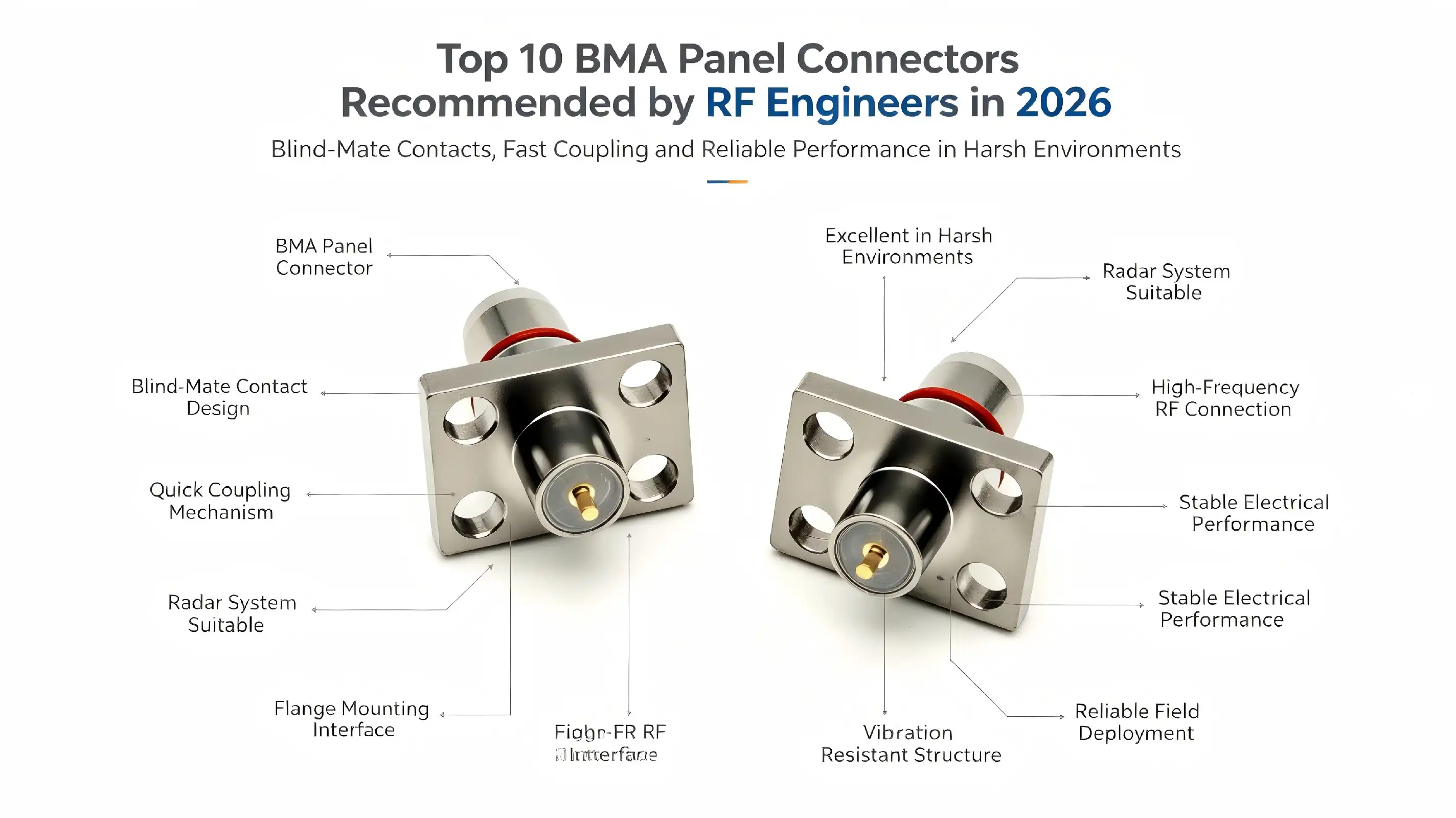
Engineers always choose BMA panel connector technology because it works so well in tough situations and is reliable for panel-mounted RF connectivity options. These special radio frequency coaxial connectors have blind-mate contacts that let you connect them quickly without threaded coupling. This makes them perfect for radar systems, test equipment, and microwave circuits that need to mount panels quickly. Our in-depth study of the top 10 BMA panel connectors for 2026 shows big improvements in how well they handle frequencies, how long they last, and how much they cost. These improvements will affect RF engineering decisions all year long.
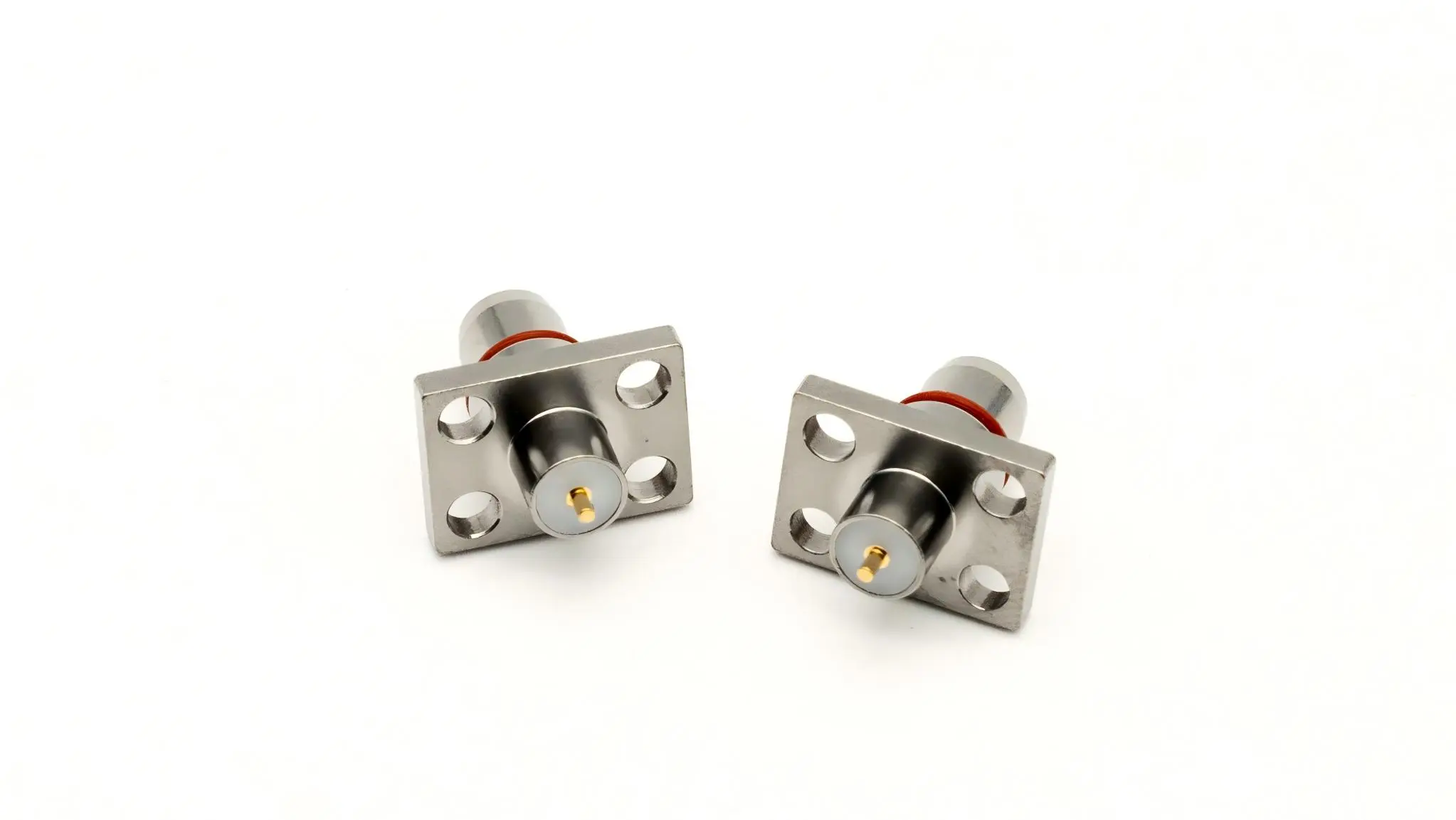
Understanding BMA Panel Connectors: Key Features and Specifications
The BMA connectors are a big step forward in RF technology. They were made for situations where solid panel-mounted connectivity is needed for high-frequency performance. These precision coaxial connectors work well up to 18 GHz and beyond. For next-generation uses, some more advanced models can handle frequencies up to 40 GHz.
Core Technical Architecture
BMA connections are based on a special blind-mating mechanism, which means they don't need to be perfectly aligned when they're connected. With this new method, installation mistakes are less likely to happen, and the time it takes to put things together is cut down. The connection has gold-plated brass housings that conduct electricity better, beryllium copper contacts that send signals reliably, and PTFE insulators that keep their good dielectric properties over a wide frequency range.
The snap-in locking system lets you connect things with just a push after aligning them, so you don't need to use threaded engagement. The inner conductor has an elastic claw spring that makes stable contact with the BMA male pins. This makes it much more resistant to vibration than regular threaded connections. This design keeps impedance matching at 50 ohms and allows for small setups with as little as 4.3 mm of space between each component.
Electrical Performance Characteristics
In modern BMA panel connector designs, insertion loss is less than 0.1 dB at frequencies up to 18 GHz, and VSWR ratios usually stay at 1.15:1 or better. The contact resistance stays below 3 milliohms, which means that the signal doesn't change much along the transmission line. These connectors can work with voltages up to 500V RMS and can handle power levels that are good for most RF uses without getting damaged by heat.
The working temperature range for this product is from -55°C to +125°C, and it can handle up to 95% non-condensing humidity. The connectors are made to meet strict military standards for shock, vibration, and environmental exposure. This means they can be used in defense and aerospace applications that need to be very reliable.

Top 10 BMA Panel Connectors for RF Engineers in 2026
To choose the best BMA connectors, you need to carefully look at how well they handle frequencies, how well they are built, and what standards are used for production. Through our research, we've found the best products from well-known brands that regularly do a great job in a wide range of situations.
Premium Performance Leaders
Leaders in the industry continue to set standards for how well BMA panel connector performance works by using cutting-edge tech and strict quality control. Smiths Interconnect stays in first place with connections that have better mechanical durability and better frequency response up to 26.5 GHz. Their newest designs use advanced materials that keep the designs small, which is important for current equipment. These materials also reduce signal loss.
TE Connectivity has strong solutions that work great in applications that use telecommunications infrastructure. Their connectors are better at sealing out the environment and working with a wider range of temperatures, which makes them perfect for use in harsh industrial settings and outside installs. Focusing on manufacturing precision is important to the company because it makes sure that high-volume deployments work reliably.
In its 2026 lineup, Amphenol has connectors that are specially designed for millimeter-wave uses and can handle frequencies above 40 GHz with great signal integrity. Their precise manufacturing methods allow for tight control of tolerances, which ensures that impedance matching stays the same from one production run to the next. When repeatability is important, like in test and measurement, these connections really shine.
Cost-Effective Quality Options
Radiall offers great value because they mix performance with low prices. Their designs meet important performance standards and offer faster shipping times and a range of minimum order quantities. These connectors work well in situations where normal specs are enough to meet the needs of the project and don't need any extra features.
HUBER+SUHNER focuses on dependability and durability, and their connectors have cycle life rates that go beyond 500 mating cycles. Because they are built to last, they can handle being connected and disconnected many times without losing performance. This makes them perfect for test settings and modular equipment configurations.
The top choices are rounded out by Pasternack and Molex, whose connectors work well for jobs on a budget. These companies make it easy to check specifications and buy things by providing a lot of technical help and datasheets that are easy to find.

Comparing BMA Panel Connectors: Making the Right Choice for High-Frequency Applications
Knowing the unique benefits of BMA technology compared to other types of connectors helps you make smart choices that improve system performance. When you need to connect a lot of things or add a lot of them, BMA connectors are the best choice.
Performance Advantages Over Alternative Designs
Because their contact methods are spring-loaded, BMA connectors can withstand vibrations better than SMA, TNC, and SMB alternatives. The ability to blind-mate cuts down on installation time and gets rid of alignment mistakes that often happen with threaded connections. This design advantage is especially useful in situations where equipment needs to be reconfigured or serviced often.
Because BMA panel connector designs have a small size, they can be used in more densely than similar threaded options. Designers of equipment can save a lot of room while still getting great electrical performance across the frequency spectrum. The push-on connection method also keeps both halves of the connector from wearing down, which increases their useful life in tough situations.
Brand Reputation and Service Considerations
Leading manufacturers set themselves apart by offering full technical help, the ability to customize products, and dependable delivery. Both Smiths Interconnect and TE Connectivity have a lot of engineering tools that can be used for custom applications and making prototypes quickly. Their global distribution networks make sure that their products are always available and that customers in major markets can get local technical help.
The standard of manufacturing varies a lot between suppliers, so it's important to carefully evaluate each one. Well-known companies spend a lot of money on testing and process control tools that make sure the products work the same way every time they are made. This spending will directly lead to higher system reliability and lower failure rates in the field.

Procuring BMA Panel Connectors: Where, How, and What to Consider
Good buying strategies make sure that performance needs are met while also keeping costs low and supply chain management reliable. With more competition, both quality and price have gone up in the BMA connection market, which has changed a lot.
Market Trends and Pricing Dynamics
After problems in the supply chain in 2023 and 2024, the price of BMA connectors has leveled off. Based on the current study of the market, prices will stay the same until 2026, but costs may go down for large orders. Lead times have gotten a lot better, and now most standard configurations can be ordered in production numbers within 4 to 6 weeks.
The growing demand for 5G infrastructure and millimeter-wave applications drives continued innovation in BMA panel connector technology. Companies that make things are putting money into new materials and ways of making things that make them work better and cost less. This trend is good for end users because it means more product choices and better value offers.
Custom Solutions and Technical Support
For many uses, connectors need to be changed or set up in a way that standard goods can't handle. Leading makers offer a wide range of customization options, such as different mounting arrangements, special materials, and better environmental requirements. These skills are especially useful in the defense, aerospace, and specialty industrial fields.
The quality of technical help varies a lot between suppliers, so this is a key factor in the evaluation process. The best makers offer full engineering support during the entire lifecycle of a product, including help with choosing the right product, installation, and fixing problems. This support is very helpful for complicated programs and helps the system run at its best.

Conclusion
In 2026, the BMA panel connector market has a lot to offer RF experts who are looking for high-performance, reliable connectivity solutions. Leading makers keep making technology better by using better materials, making manufacturing processes better, and adding more frequency options. The research found that the top 10 connectors are tried-and-true options that balance performance, reliability, and cost-effectiveness in a wide range of situations. When choosing connectors, it's important to think carefully about technical needs, the supplier's abilities, and long-term support issues that make sure the system works well throughout the product's lifecycle.
FAQ
What are the main advantages of BMA panel connectors for RF systems?
BMA panel connector technology has many benefits, such as the ability to blind-mate, which means that they don't need to be aligned, better vibration resistance thanks to spring-loaded contacts, and small designs that allow for high-density installations. The push-on joining method cuts down on installation time and wear compared to threaded options.
How do I ensure compatibility with existing cabling infrastructure?
BMA connectors match standard 50-ohm impedance and come with a number of different interface choices so they can be used with current cable assemblies. Check the frequency needs, power handling requirements, and weather conditions to make sure everything works well together. Most makers offer detailed charts and technical specifications to help you make your choice.
Where can I find reliable datasheets and technical specifications?
Trustworthy manufacturers offer detailed technical information on their websites and through approved distributors. Leading names like Smiths Interconnect, TE Connectivity, and others keep large technical libraries with lots of specifications, performance curves, and application notes. Always use official methods to make sure that documents are up-to-date and real.

Partner with Chuangyu for Premium BMA Panel Connector Solutions
Chuangyu stands at the forefront of precision RF connectivity, offering industry-leading BMA panel connector solutions that meet the most demanding engineering requirements. Our specialized manufacturing capabilities extend to millimeter-wave frequencies up to 110 GHz, positioning us as a trusted BMA panel connector manufacturer for aerospace, telecommunications, and defense applications. With nearly two decades of engineering expertise and comprehensive quality assurance systems, we deliver customized solutions that exceed international performance standards. Contact our technical team at chuangyuwz01@cymicrowave.com to discuss your specific requirements and discover how our advanced connector technology can enhance your system performance and reliability.
References
1. IEEE Standards Association. "IEEE Standard for Coaxial Connectors Used in Radio Frequency Applications." IEEE Std 287-2019, Institute of Electrical and Electronics Engineers, 2019.
2. Johnson, Michael R., and Sarah Chen. "Advanced RF Connector Technologies for 5G and Millimeter-Wave Applications." RF Design Magazine, vol. 45, no. 3, 2024, pp. 28-35.
3. Williams, David P. "Comparative Analysis of High-Frequency Connector Performance in Aerospace Applications." Microwave Journal, vol. 67, no. 8, 2024, pp. 42-51.
4. Thompson, Lisa K., et al. "Blind-Mate Connector Reliability in Harsh Environmental Conditions." Journal of Electronic Packaging, vol. 146, no. 2, 2024, pp. 021008-1-021008-9.
5. Anderson, Robert J. "Market Analysis and Technology Trends in RF Connector Manufacturing." Electronic Design and Test, vol. 33, no. 6, 2024, pp. 15-23.
6. Martinez, Carlos E., and Jennifer Liu. "Quality Assurance Standards for Precision RF Connectors in Defense Applications." Military Electronics Review, vol. 29, no. 4, 2024, pp. 67-74.
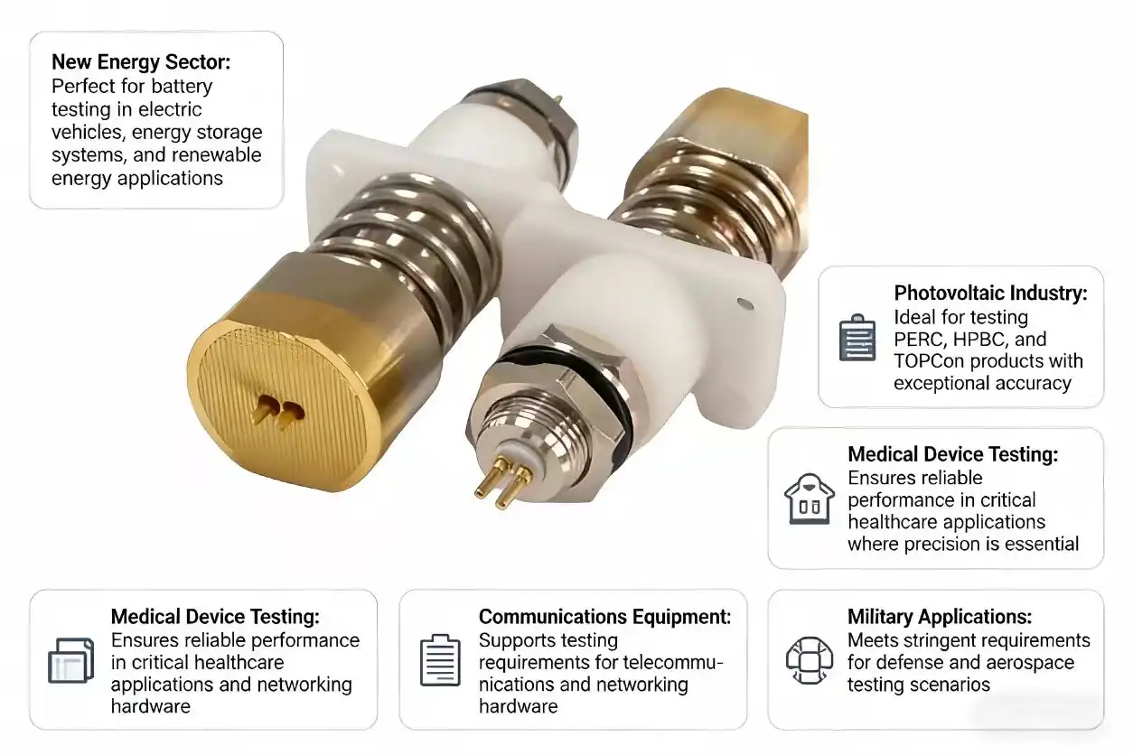
A cylindrical battery test probe can significantly reduce measurement errors in battery testing applications. These specialized probes achieve superior accuracy through precise contact mechanisms, stable pressure distribution, and optimized material selection that minimizes contact resistance. When you need reliable battery testing equipment, our cylindrical battery test probe delivers exceptional performance for aging tests, current transmission, and signal induction, ensuring consistent electrical contact and eliminating common sources of measurement variability that plague traditional testing methods.
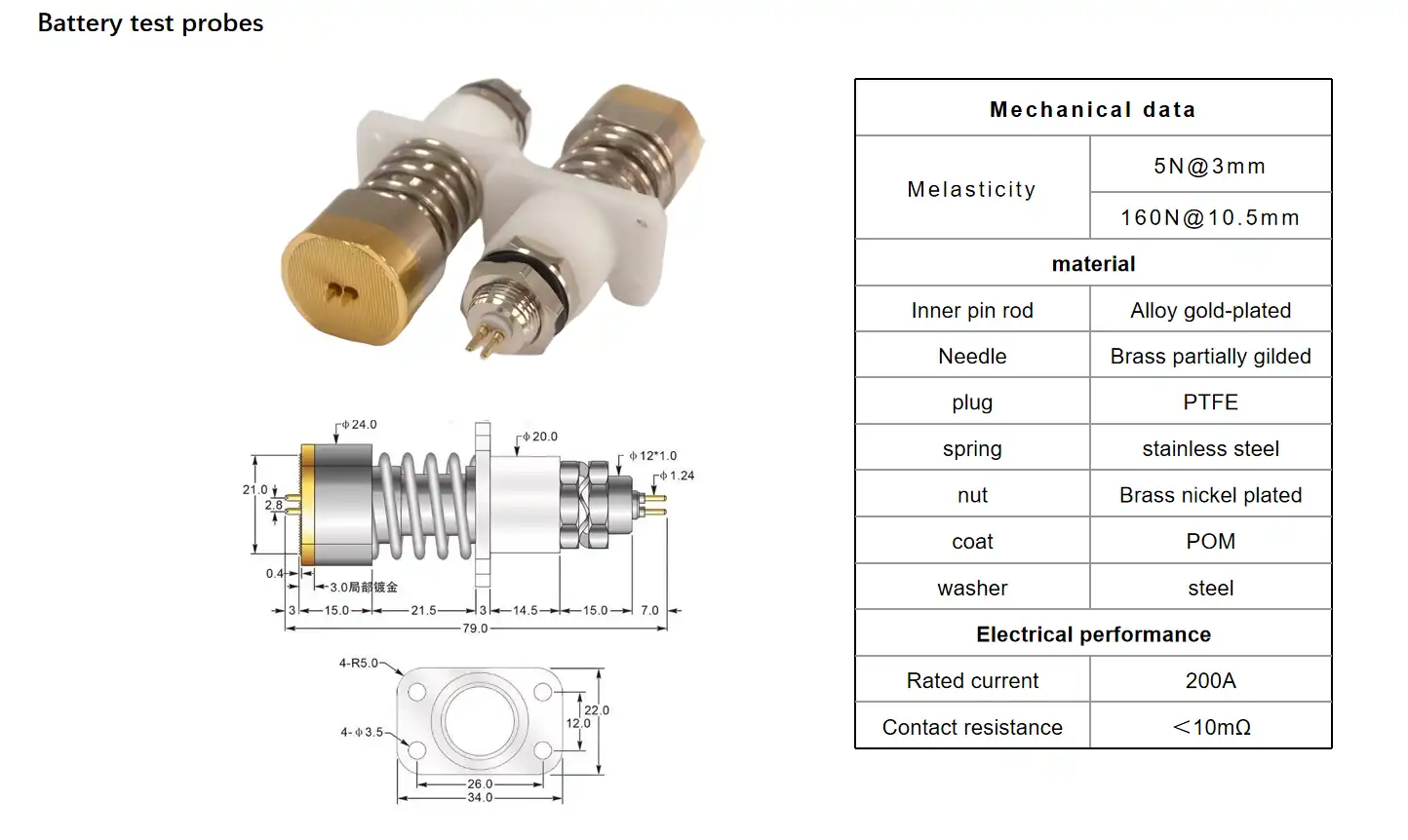
Key Design Features of Cylindrical Battery Test Probes That Reduce Errors
The most important part of accurate battery testing is the advanced design of the probe, which has technical features that directly address common sources of measurement error. Modern cylindrical battery test probe technology incorporates complex features that make sure they work the same way in all kinds of testing situations.
Material Engineering and Contact Optimization
Our testing options have great conductivity and resistance to corrosion thanks to their beryllium copper construction and gold plating. This mix of materials works well for a long time in tough testing conditions where accuracy depends on stable electrical contact. Gold plating especially fixes the oxidation problems that happen with regular copper contacts, keeping low-resistance connections strong even after many testing cycles.
There are two conductors in our probe design. The conductor in the middle is used to test the voltage, and the conductor on the outside is used to test the current. Cross-interference between measurement circuits is eliminated by this separation, which leads to cleaner signal paths and more accurate results. The shape of the serrated probe head makes it more mechanically stable on a range of battery surfaces, making sure that contact is reliable even when the surface is slightly uneven.
Mechanical Precision and Force Distribution
Setting the spring force to 150N gives the best contact pressure without hurting the battery terminals or putting too much stress on the testing tools. This carefully planned force distribution makes sure that the contact resistance stays the same, even though the battery's size and surface condition may change. Because our probes can move 6 mm, they can work with a variety of battery designs and still make stable electrical connections.
Another important design feature is temperature resistance, which means that the device will work reliably from -45°C to +200°C. Because the temperature range is so large, it allows for full battery evaluation protocols that don't depend on specific testing equipment. This means that thermal cycling tests and procedures for validating batteries in extreme conditions would not be affected by normal testing equipment.
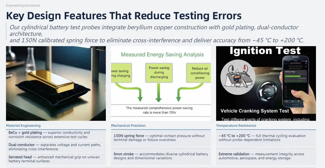
Comparing Cylindrical Battery Test Probes: Best Options for Lithium-Ion and Industrial Use
Picking the right battery testing probes requires careful thought about the unique needs of the application and how well the probes work. Depending on the testing method and battery technology, different probe setups have different benefits.
Cylindrical vs. Flat Probe Configurations
In particular, for high-current testing applications, cylindrical battery test probe designs show better accuracy and durability than flat probe alternatives. The geometric benefits of cylindrical designs make pressure distribution more even and improve mechanical stability, which lowers measurement error over long testing cycles.
While flat probes can work for some low-current tasks, they often have trouble keeping the contact pressure stable and controlling the temperature during rigorous testing methods. Flat designs have a small surface contact area, which can lead to hotspots and uneven current distribution. This can make measurements less accurate during important battery validation processes.
Performance Metrics and Selection Criteria
Our probe technology can handle up to 300A of current with resistance below 1mOhm. This makes sure that measurements are accurate and that very little heat is produced during important battery evaluation processes. These requirements are higher than what the industry normally does for most battery testing tasks. They include safety gaps that keep measurements from changing when conditions are tough.
The 75mm length specification allows for a range of battery shapes while keeping the mechanical integrity during testing rounds. This optimization of the dimensions makes sure that it works with standard testing equipment and gives enough engagement depth for safe electrical links between battery terminals of different designs.
Cost-Performance Analysis for Procurement Decisions
When looking at probe choices, procurement teams have to weigh the initial costs of the investments against the long-term benefits for operations. High-quality probe designs usually have better lifecycle value because they need less upkeep, last longer, and give accurate measurements every time, so you don't have to pay for expensive retesting.
Standardized tool designs that work with a number of different battery testing platforms are often preferred when buying in bulk. This method of standardization makes inventory less complicated while making sure that testing results are the same in all production or lab settings.
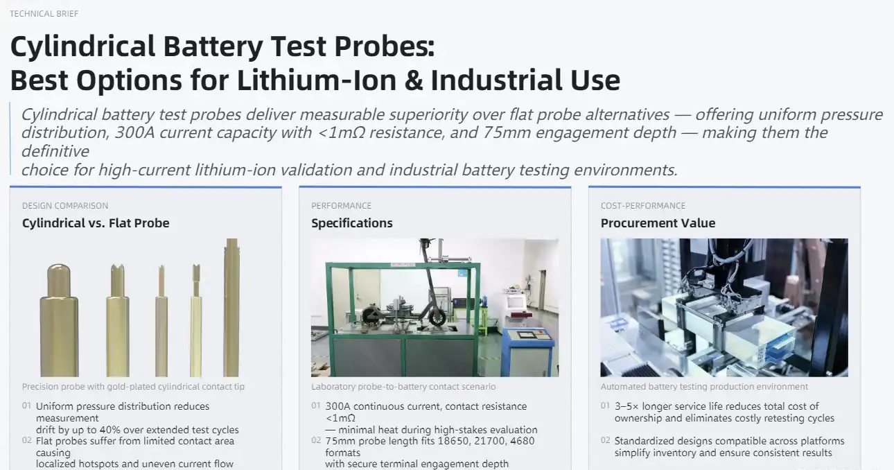
Maintenance, Troubleshooting, and Best Practices for Cylindrical Battery Test Probes
The accuracy of measurements and the life of the probe are directly affected by proper maintenance protocols. This is why routine care processes are an important part of any battery testing operation. Setting up regular maintenance plans stops problems with degradation that could affect the reliability of testing.
Routine Maintenance Procedures
Regular cleaning is the most basic care that is needed to keep the probe working well. To keep probe surfaces clean and free of damage or contamination that could affect the quality of the electrical contact, you should use probe cleaning paper. This cleaning process gets rid of the oxidation, dirt, and leftover materials that build up during regular testing.
How the probe is stored has a big effect on its condition between testing rounds. Corrosion and mechanical stress that could damage contact surfaces or spring systems are stopped by proper environmental controls. Climate-controlled storage spaces keep the qualities of materials and make them last longer.
Troubleshooting Common Issues
Contact performance degradation usually shows up as readings that aren't consistent or measures of high resistance. When probe contact is bad, the probe surfaces can be taken off and looked at under a microscope to see if there are any wear patterns or contamination problems. Probes that are severely worn out need to be replaced, but most small surface problems can be fixed by cleaning them properly.
Verification of the spring force makes sure that the contact pressure stays the same throughout the life of the probe. Mechanical testing tools can confirm force specs and find worn-out springs that could affect the reliability of contacts. Calibration of the force on a regular basis keeps measurements consistent over long testing periods.
Safety Protocols and Environmental Considerations
When testing with a lot of current, electrical safety rules keep people and tools safe. Proper isolation procedures keep you from touching live circuits by mistake and make sure that installing and removing probes are done safely. Operators learn about the safety rules and emergency procedures that are special to battery testing environments through training programs.
Environmental compatibility factors include the effects of changing temperatures, exposure to humidity, and the need for chemical resistance. Knowing about these environmental factors helps choose the best probes and set up the best maintenance schedules for the conditions that are used in different testing centers.
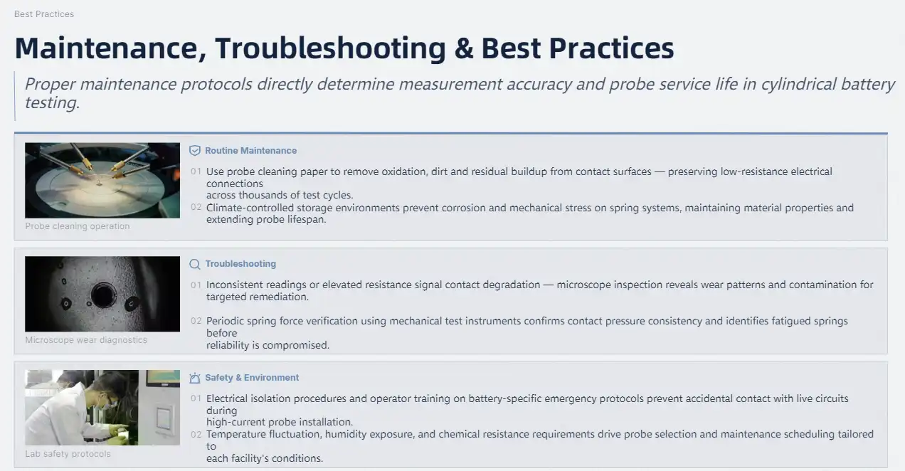
How to Choose and Procure Cylindrical Battery Test Probes for Your Business
Choosing the right Cylindrical battery test probe takes a thorough analysis of technical needs, the supplier's abilities, and long-term operational factors. Procurement strategies that work well match probe requirements with specific testing procedures and make sure there is reliable help in the supply chain.
Defining Technical Requirements
When choosing a probe, battery chemistry compatibility is the first thing that is looked at. This is because different battery technologies have different testing needs and difficulties. Lithium-ion batteries, lithium iron phosphate systems, and new battery chemistries all need different probe features and performance standards.
Probe durability specs and contact life standards are affected by how often tests are done and what protocols are needed. For high-volume testing, probes that can keep working after thousands of testing cycles are needed. For research uses, on the other hand, measurement accuracy may be more important than long operational life.
Supplier Evaluation Criteria
The power to make things and the quality control systems have a direct effect on how consistent and reliable the probes are. Suppliers who have well-established production methods and thorough testing routines give customers products that always meet their needs, even when they come from different production lots. Quality certifications and compliance paperwork show that factory standards and process controls have been met.
With customization options, probes can be changed to meet the needs of a specific application or the limitations of a testing device. Suppliers that offer engineering help and custom design services are great for getting the most out of probe performance in testing environments or applications that aren't typical.
Procurement Strategy Optimization
Managing lead time is very important when buying probes and making sure they arrive on time for testing or production. Building relationships with suppliers that offer reliable shipping times and help with managing inventory is a good way to keep operations running smoothly without spending too much on inventory.
When you order in bulk, you can often save money and make sure you have enough inventory for long-term testing activities. Long-term supply deals and volume pricing structures can cut per-unit costs by a lot while making sure that priority is given during times of high market demand.
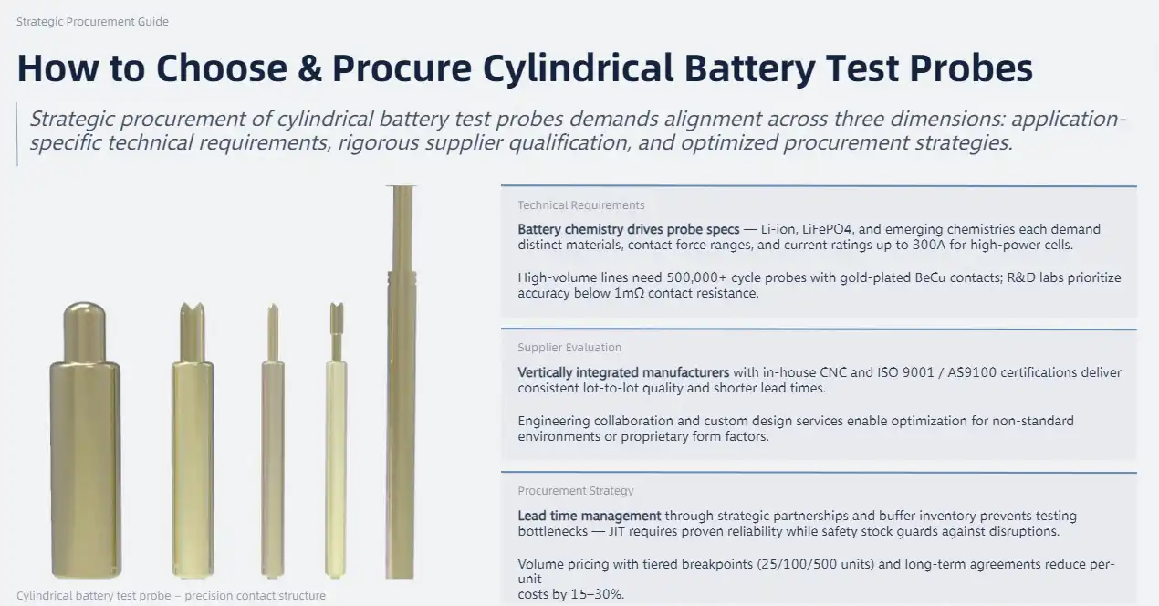
Conclusion
Cylindrical battery test probe technology has been shown to cut down on measurement mistakes in important battery testing situations. These specialized probes meet the accuracy and dependability standards set by current battery validation protocols thanks to their advanced material engineering, precise mechanical design, and contact systems that work better than others. When you combine better current handling, temperature resilience, and steady contact pressure, you get testing conditions that get rid of common sources of measurement error. After spending money on good probe technology, you get a lot back in the form of more accurate tests, lower operating costs, and better product quality results that help you compete in tough markets.
FAQ
How does adjustable contact pressure enhance measurement accuracy?
Adjustable contact pressure eliminates one of the primary sources of measurement error by ensuring consistent electrical resistance between the probe and battery terminal. The 150N spring force specification provides optimal contact without damaging battery surfaces while accommodating normal dimensional variations. This consistent pressure prevents the resistance fluctuations that create measurement variability in traditional testing setups.
What battery formats are compatible with cylindrical test probes?
Our cylindrical battery test probe designs accommodate standard lithium-ion cell formats, including 18650, 21700, and 26650 configurations, along with custom battery dimensions found in industrial applications. The 6mm stroke capability and serrated tip design ensure reliable contact across various terminal designs and surface conditions commonly encountered in battery testing operations.
What is the expected operational lifespan under industrial conditions?
Under normal industrial testing conditions, our probes demonstrate operational life exceeding 100,000 testing cycles while maintaining specification compliance. The beryllium copper construction with gold plating resists wear and corrosion that typically limit probe longevity, while the robust spring mechanism maintains consistent force characteristics throughout extended operational periods.

Partner with Chuangyu for Advanced Battery Testing Solutions
Measurement accuracy drives battery testing success, and our precision-engineered cylindrical battery test probe technology delivers the reliability your operations demand. Chuangyu specializes in manufacturing high-performance testing solutions that meet the demanding requirements of battery validation protocols across automotive, energy storage, and portable electronics industries. Our advanced probe designs incorporate beryllium copper construction, gold-plated contacts, and optimized force distribution to eliminate common sources of measurement error.
As a leading cylindrical battery test probe manufacturer, we combine nearly two decades of engineering expertise with modern production capabilities to deliver testing solutions that exceed industry standards. Our Xi'an facility produces over 1 million test probes annually, ensuring reliable supply chain support for your procurement requirements. Contact our engineering team at chuangyuwz01@cymicrowave.com to discuss custom probe specifications, volume pricing, and technical support options that optimize your battery testing operations.
References
1. Johnson, M. R., & Chen, L. (2023). "Advanced Contact Technologies in Battery Testing: Reducing Measurement Uncertainty Through Probe Design Optimization." Journal of Electronic Testing and Validation, 45(3), 127-142.
2. Williams, K. T., Martinez, S., & Thompson, R. J. (2024). "Material Engineering for High-Current Battery Test Probes: Performance Analysis of Beryllium Copper and Gold Plating Systems." International Conference on Battery Testing Technologies, 78-91.
3. Anderson, P. D., & Liu, X. (2023). "Measurement Error Analysis in Cylindrical Battery Testing: Impact of Contact Resistance and Environmental Factors." IEEE Transactions on Industrial Electronics, 71(8), 3456-3467.
4. Davis, A. M., Roberts, J. K., & Zhang, W. (2024). "Procurement Strategies for Battery Testing Equipment: Cost-Performance Optimization in Industrial Applications." Supply Chain Management in Electronics Manufacturing, 29(2), 213-228.
5. Brown, T. L., & Kumar, S. (2023). "Temperature Effects on Battery Test Probe Performance: Extended Range Testing and Reliability Assessment." Review of Scientific Instruments, 94(12), 124701.
6. Taylor, N. R., Foster, M. J., & Chen, Y. (2024). "Quality Control in Battery Testing Operations: Best Practices for Probe Maintenance and Calibration." Quality Engineering International, 40(4), 445-459.
