- English
- French
- German
- Portuguese
- Spanish
- Russian
- Japanese
- Korean
- Arabic
- Greek
- German
- Turkish
- Italian
- Danish
- Romanian
- Indonesian
- Czech
- Afrikaans
- Swedish
- Polish
- Basque
- Catalan
- Esperanto
- Hindi
- Lao
- Albanian
- Amharic
- Armenian
- Azerbaijani
- Belarusian
- Bengali
- Bosnian
- Bulgarian
- Cebuano
- Chichewa
- Corsican
- Croatian
- Dutch
- Estonian
- Filipino
- Finnish
- Frisian
- Galician
- Georgian
- Gujarati
- Haitian
- Hausa
- Hawaiian
- Hebrew
- Hmong
- Hungarian
- Icelandic
- Igbo
- Javanese
- Kannada
- Kazakh
- Khmer
- Kurdish
- Kyrgyz
- Latin
- Latvian
- Lithuanian
- Luxembou..
- Macedonian
- Malagasy
- Malay
- Malayalam
- Maltese
- Maori
- Marathi
- Mongolian
- Burmese
- Nepali
- Norwegian
- Pashto
- Persian
- Punjabi
- Serbian
- Sesotho
- Sinhala
- Slovak
- Slovenian
- Somali
- Samoan
- Scots Gaelic
- Shona
- Sindhi
- Sundanese
- Swahili
- Tajik
- Tamil
- Telugu
- Thai
- Ukrainian
- Urdu
- Uzbek
- Vietnamese
- Welsh
- Xhosa
- Yiddish
- Yoruba
- Zulu
knowledge
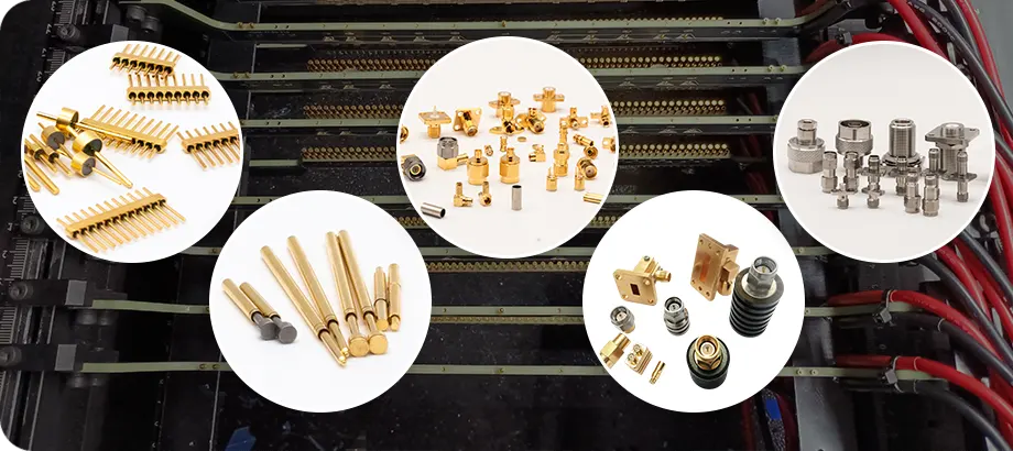
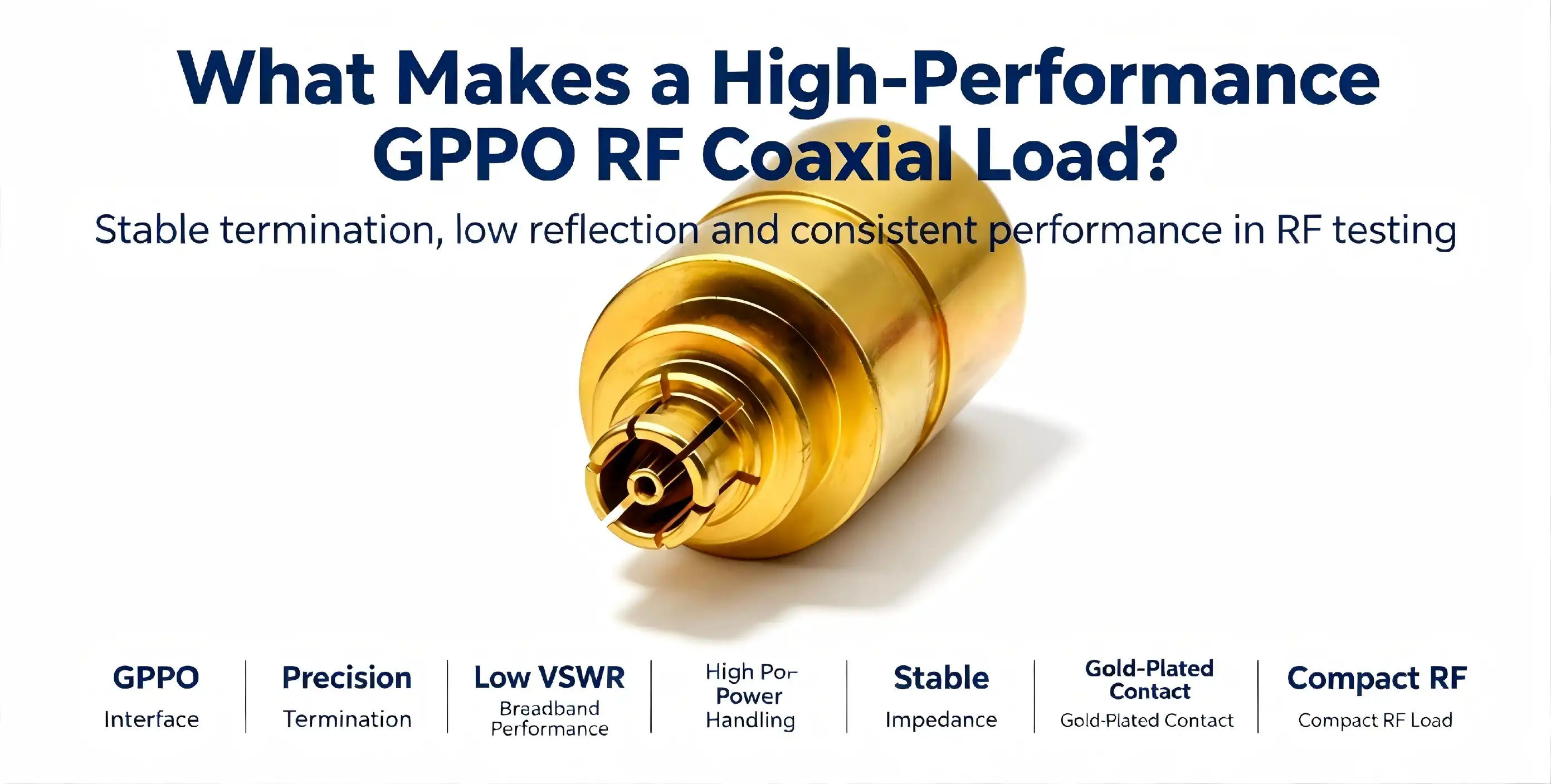
When your test bench needs millimeter-wave accuracy, every part counts. Signal integrity meets thermal stability at a GPPO RF coaxial load, ensuring precise measurements up to 65 GHz. These RF terminations absorb electromagnetic radiation while matching impedance, eliminating reflections that reduce the measurement accuracy of vector network analysers, spectrum analysers, and signal generator measurements. R&D engineers and procurement managers are under pressure to select components that function consistently throughout increasing frequency ranges. The migration to 5G infrastructure, satellite communications, and 6G prototypes requires small termination solutions with excellent electrical properties. This paper covers the technical qualities, application considerations, and sourcing methods of high-performance RF loads, helping you make educated purchase choices in challenging test conditions.
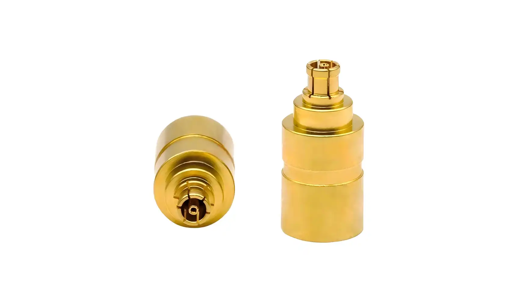
Understanding GPPO RF Coaxial Loads: Definitions, Features, and Applications
A GPPO RF coaxial load operates fundamentally as a precision termination that converts electromagnetic energy into heat while maintaining a standard 50Ω impedance. High-performance coaxial terminations achieve this through carefully engineered resistive elements—typically tantalum nitride resistive layers bonded to high-thermal-conductivity ceramic substrates. This construction enables controlled power dissipation without introducing signal reflections that distort measurement accuracy.
What Defines a High-Performance RF Termination
High-performance millimeter-wave loads distinguish themselves through three interconnected characteristics: ultra-wideband frequency coverage from DC to 65 GHz, minimal voltage standing wave ratio (VSWR ≤1.45), and adequate power handling capacity of 2W at standard temperatures. The combination of brass gold-plated outer conductors with polytetrafluoroethylene insulating media ensures signal integrity across the entire operational spectrum while withstanding mechanical stress from repeated connections.
Technical Specifications That Matter
Modern RF test loads incorporate SSMP male connectors featuring push-in connection mechanisms that eliminate tool requirements during assembly. The brass body construction supports ≥500 insertion-extraction cycles while maintaining electrical performance across an operating temperature range of -55℃ to +125℃. Compact metal packaging designs achieve these specifications while occupying minimal board space—essential for high-density RF subsystems where every millimeter counts.
Common Application Scenarios
The major use is millimeter-wave test measurement, where these loads are vector network analyser and signal generator terminal impedances. System calibration and device characterisation at 65 GHz need termination stability for reliable reference measurements. These components provide dummy GPPO RF coaxial loads and impedance matching for micro-interconnect modules in high-density RF subsystems of millimeter-wave radar and satellite communication equipment in aerospace and military applications. In severe space restrictions, 6G prototype development and ultra-compact test devices need signal absorption capabilities. Standard connection types are unfeasible.
Core Technical Features That Define High Performance in GPPO RF Coaxial Loads
Performance differentiation in RF terminations emerges from the interplay between materials science, thermal management, and precision manufacturing. Understanding these technical foundations enables specification decisions aligned with actual test requirements rather than generic component parameters.
Frequency Range Coverage and Power Rating
The DC to 65 GHz frequency coverage represents a defining characteristic, supporting measurements across traditional microwave bands through millimeter-wave frequencies. This continuous bandwidth eliminates the need for multiple load types across different frequency ranges, simplifying test setups and reducing inventory complexity. The 2W power capacity at 25℃ ambient temperature accommodates typical signal generator output levels while maintaining measurement accuracy, though capacity reduces to 0.2W at the upper temperature limit of 125℃—a critical derating factor for thermal management planning.
Durability Through Material Selection
Tantalum nitride resistive layers bonded to high thermal conductivity ceramic substrates form the core power-dissipating element. This material combination achieves stable impedance characteristics across wide frequency ranges while efficiently transferring thermal energy away from the resistive junction. Brass gold-plated construction provides both oxidation resistance and excellent electrical conductivity, maintaining connector performance through hundreds of mating cycles. The polytetrafluoroethylene insulating medium offers low dielectric loss and thermal stability, preserving signal integrity in demanding operating environments.
Connector Compatibility and Signal Integrity
SSMP connectors have lower parasitic inductance and capacitance than SMA or BNC connectors, improving high-frequency performance. Push-in mating delivers uniform contact force without threaded coupling variations, enabling reproducible VSWR measurements. In high-reliability applications where intermittent connections induce measurement error, gold plating on mating surfaces decreases contact resistance and prevents galvanic corrosion, which affects connection quality.
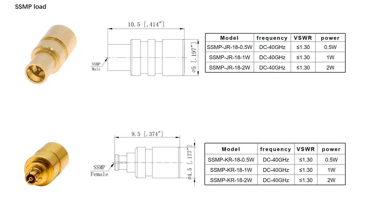
Comparing GPPO RF Coaxial Loads With Alternative RF Loads – Making the Right Choice
Understanding the competitive landscape helps procurement teams select appropriate termination technology for specific applications. Different connector families offer distinct advantages depending on frequency requirements, power handling needs, and mechanical constraints.
GPPO Versus SMA Terminations
SMA connections dominate RF testing due to their dependability and ability to operate up to 18 GHz with precision variations up to 26.5 GHz. GPPO RF coaxial loads cover DC to 65 GHz with decreased connection size and optimised dielectric interfaces. SMA footprints take up too much space on high-density circuit boards; hence, the small form factor is important. Power handling is comparable for technologies at similar price ranges; however,ver thermal management needs grow with frequency owing to decreasing conductor cross-sections.
N-Type and BNC Alternatives
N-type connectors excel in high-power applications, handling significantly greater power levels than miniature connector formats while maintaining adequate performance to 18 GHz. Applications requiring robust mechanical coupling and exposure to harsh environments benefit from N-type construction, though the larger connector body limits utility in space-constrained designs. BNC connectors offer quick-connect convenience for applications below 4 GHz but lack the frequency response necessary for millimeter-wave measurements. RF component testing requires careful matching between connector technology and actual frequency ranges to avoid systematic measurement errors introduced by connector limitations.
Supplier Reliability and Certification Considerations
Beyond component specs, B2B buying choices include supplier trust, production uniformity, and after-sales assistance. Reliable manufacturers give complete test data showing electrical specification compliance across manufacturing batches, lowering inspection requirements. AS9100 certification shows aerospace sector quality requirements for high-reliability applications, whereas ISO 9001 certification shows systematic quality management. Warranty, technical support, and calibration services lower the total cost of ownership beyond the original purchase price.
Procurement Insights – How to Source High-Quality GPPO RF Coaxial Loads Efficiently
Strategic sourcing balances technical requirements, delivery timelines, and budget constraints while managing supply chain risks. Effective procurement strategies incorporate multiple evaluation criteria beyond unit price to optimize total acquisition costs.
Identifying Trusted Manufacturers and Distributors
Chuangyu specializes in precision RF components with manufacturing capabilities extending to 110 GHz, offering comprehensive solutions for millimeter-wave applications. Their production facility in Xi'an Chang'an Innovation Technology Industrial Park operates integrated manufacturing lines producing 500,000 RF components and 1 million test probes annually, supporting both prototype quantities and volume production requirements. Direct manufacturer relationships provide access to technical expertise during specification development, customization options for non-standard requirements, and transparent quality documentation tracing manufacturing processes.
Pricing Structures and Lead Time Management
Component pricing reflects complexity factors including frequency range, power handling, and connector type, with millimeter-wave devices commanding premium pricing due to precision manufacturing requirements. Minimum order quantities vary significantly—catalog items may ship in single-piece quantities while custom configurations require minimum commitments justifying tooling investments. Lead times span 2-4 weeks for standard products versus 6-12 weeks for customized solutions, necessitating advance planning aligned with project schedules. Volume discounts typically activate at 100-piece quantities, with escalating discounts at 500- and 1,000-piece thresholds that substantially reduce per-unit costs for production programs.
Customization and After-Sale Support
Standard catalog offerings address common requirements, yet specialized applications often demand modified specifications—altered connector types, adjusted power ratings, or enhanced temperature ranges. Manufacturers with in-house design capabilities can adapt existing platforms more rapidly than those relying on third-party engineering resources. Comprehensive after-sale support includes calibration services, failure analysis for returned components, and application engineering consultation addressing integration challenges. These services prove particularly valuable during new product development when unforeseen technical issues emerge requiring rapid resolution to maintain program schedules.
Best Practices and Testing Methods to Ensure Optimal GPPO RF Coaxial Load Performance
Component specifications define capabilities under ideal conditions, yet achieving rated performance requires proper handling, installation, and maintenance practices throughout operational lifecycles.
Installation and Connection Standards
Push-in connection mechanisms demand careful coaxial alignment during insertion to prevent inner conductor deformation that degrades electrical performance. Applying lateral force or twisting during mating can misalign conductors, creating intermittent connections or permanent damage. The 90° bent configurations require particular attention to bending radius—maintaining a minimum 3.6mm radii prevents cable damage and connector stress that shortens service life. Proper installation technique directly impacts long-term reliability and measurement repeatability.
Environmental Protection Measures
Environments exceeding 60% relative humidity require dust caps when connectors remain unmated, preventing moisture ingress and corrosive gas exposure that attacks gold-plated surfaces. Contamination accumulation on mating interfaces increases contact resistance and introduces measurement uncertainty. Operating temperature ranges span -55℃ to +125℃, though power capacity decreases at elevated temperatures—power must decrease to 0.2W at the upper temperature limit to prevent thermal damage. Instantaneous peak power handling reaches 200W, accommodating pulsed signals common in radar and communication testing.
Routine Maintenance and Performance Verification
The cleaning protocol recommends isopropyl alcohol swabs after every 20 insertion cycles, carefully wiping connector end faces while focusing on gold-plated contact areas. Metal tools must never contact insulating media interfaces, as scratches compromise dielectric integrity and introduce leakage paths. Storage conditions maintain -20℃ to +60℃ with relative humidity below 50%, preserving connector integrity during idle periods. Monthly VSWR verification detects performance degradation requiring recalibration or replacement, preventing subtle measurement errors that compromise test validity.
Lifecycle Management Strategies
Total working hours exceeding 1,500 hours or exposure to severe mechanical shock triggers full-spectrum performance verification using network analyzers. This comprehensive assessment evaluates VSWR and power capacity across the entire DC to 65 GHz range, confirming continued compliance with specifications. Components failing verification require factory recalibration or replacement, as degraded terminations introduce systematic measurement errors affecting all subsequent tests. Proactive lifecycle management prevents undetected performance degradation that silently compromises measurement accuracy over extended periods.
Conclusion
High-performance GPPO RF coaxial load terminations meet millimeter-wave measurements with precise materials, thermal control, and manufacturing experience. Essential technical qualities for current test settings include 65 GHz frequency coverage, VSWR ≤1.45, 2W power capacity, and sturdy mechanical design. Strategic procurement strategies balance technological needs, supplier dependability, and lifecycle costs to optimise purchase choices and manage supply chain risks. Effective installation, environmental protection, and periodic maintenance maintain rated performance over operating lifecycles, maintaining measurement integrity and equipment investments.
FAQ
1. What frequency ranges do GPPO RF coaxial loads typically cover?
High-performance millimeter-wave terminations cover DC to 65 GHz, supporting measurements across microwave and millimeter-wave bands without requiring multiple load types. This continuous bandwidth accommodates both traditional and emerging communication standards, including 5G and developmental 6G systems.
2. How do GPPO loads compare to SMA terminations?
GPPO RF coaxial loads extend frequency coverage significantly beyond standard SMA connectors, reaching 65 GHz compared to 18-26.5 GHz for precision SMA variants. The compact form factor reduces board space requirements, while the push-in connection mechanism ensures consistent contact force and repeatable measurements.
3. Can I order customized GPPO terminations for specialized applications?
Manufacturers with in-house design capabilities offer customization options addressing specific connector types, power ratings, or temperature ranges beyond standard catalog offerings. Custom solutions typically require minimum order commitments and extended lead times but enable optimization for unique application requirements.

Partner With Chuangyu for Superior RF Termination Solutions
Chuangyu delivers precision-engineered millimeter-wave components backed by nearly two decades of RF manufacturing expertise. Our production capabilities support frequencies up to 110 GHz with comprehensive quality control ensuring electrical performance and mechanical reliability. Whether your project demands standard catalog items or customized termination solutions, our technical team provides application-specific guidance from specification development through production integration.
Contact our specialists at chuangyuwz01@cymicrowave.com to discuss your GPPO RF coaxial load requirements. We offer competitive pricing for volume orders, rapid prototyping capabilities, and comprehensive after-sale support, including calibration services and technical consultation. As a trusted GPPO RF coaxial load supplier, we're committed to delivering solutions that enhance your test capabilities while meeting aggressive project timelines.
References
1. Pozar, D. M. (2012). Microwave Engineering, 4th Edition. John Wiley & Sons, Inc.
2. Eisenhart, R. L., & Khan, P. J. (2006). "A Review of the State-of-the-Art in RF and Microwave Connectors," IEEE Transactions on Components and Packaging Technologies, 29(3), 515-528.
3. Holloway, C. L., & Kuester, E. F. (2009). "A Low-Frequency Model for Wedge or Pyramid Absorber Arrays," IEEE Transactions on Electromagnetic Compatibility, 51(3), 530-536.
4. Collin, R. E. (2001). Foundations for Microwave Engineering, 2nd Edition. Wiley-IEEE Press.
5. Maloratsky, L. G. (2004). Passive RF and Microwave Integrated Circuits. Elsevier Science & Technology.
6. Bahl, I. J. (2009). Fundamentals of RF and Microwave Transistor Amplifiers. John Wiley & Sons, Inc.
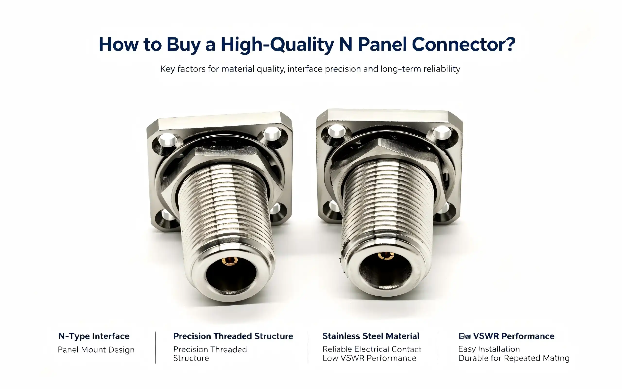
When purchasing a high-quality N-panel connector, it is important to know the technical demands of your system, the environmental conditions it will be exposed to, and the long-term dependability requirements. These RF components are the vital link between your equipment chassis and external signal transmission lines; thus, the selection of RF components is important to the functioning of your system. Whether you’re an R&D engineer developing communications infrastructure or a procurement manager procuring components for semiconductor testing equipment, the selection of the correct panel-mounted RF connection directly affects signal integrity, operational uptime and maintenance costs. This book will take you through the key assessment criteria, technical specifications and practical procurement tactics to help you make informed buying selections that meet your application needs and budget.
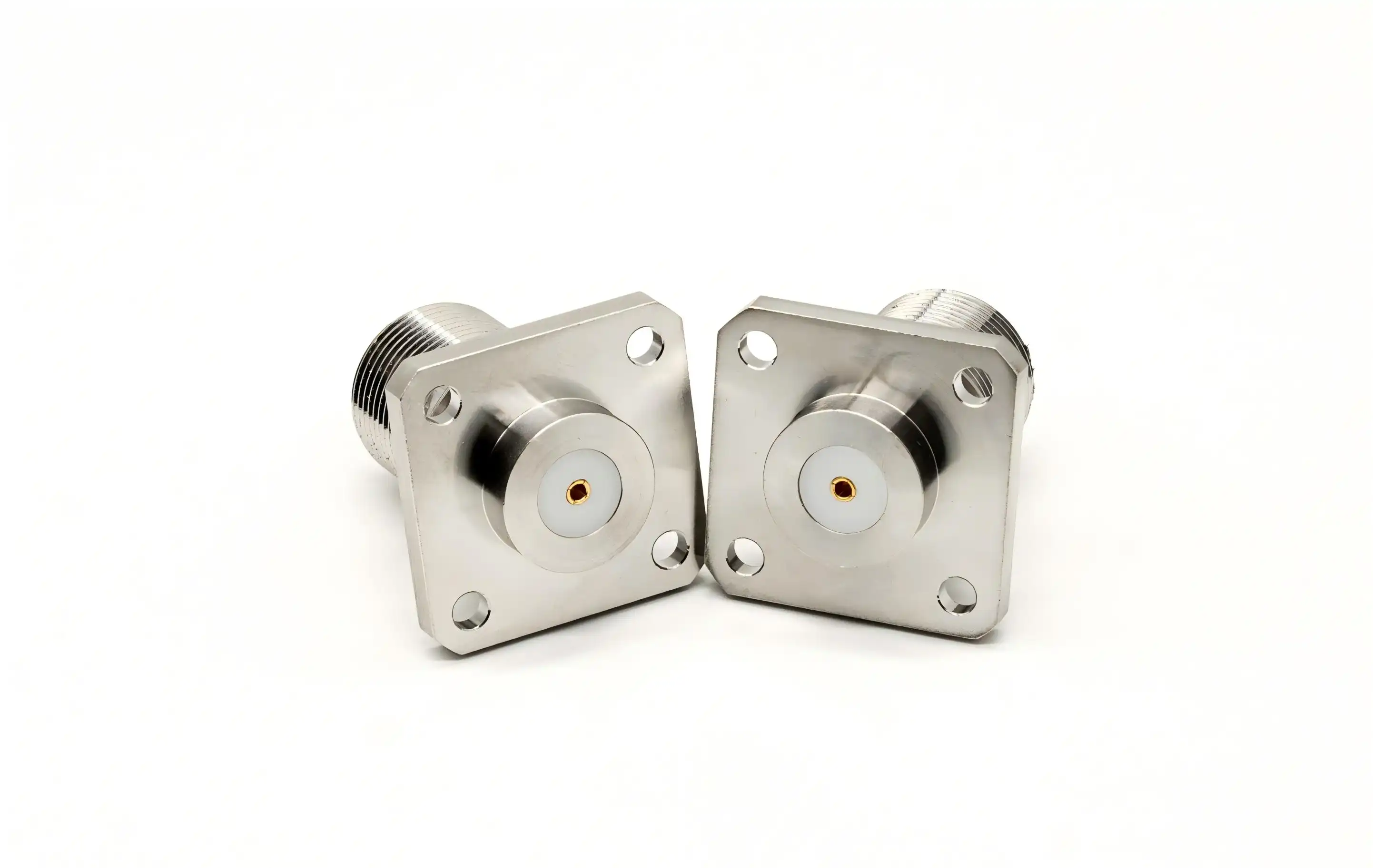
Criteria to Evaluate High-Quality N Panel Connectors
Environmental Protection and Mechanical Durability
Rugged RF Connectors for Panel Mount Applications should be rugged enough to endure the physical stress and environmental conditions found in your application environment. The IP rating system is a standard measure for ingress protection, and IP67-rated connections are dust-tight sealed and protected against momentary immersion. If you are choosing connections for outdoor telecommunications equipment or solar installations, be sure to check the IP rating via third-party certification and not only on the basis of manufacturer statements. If you’re working in a coastal or marine setting, you’ll want salt spray protection, so seek connections that satisfy ASTM B117 for a minimum of 96 hours of exposure without corrosion.
Mechanical resilience is a key factor in ensuring long-term dependability during repeated connection cycles and environmental stress. PremiumN panel connectors should be capable of 500 mating cycles minimum without compromise of electrical performance or mechanical integrity. The threaded connection must have a constant engagement torque of 12 - 15 inch-pounds throughout the life of the connector. Check flange thickness and hole reinforcement; thin flanges will flex under installation tension, leading to misalignment and probable seal failure. Corrosion-resistant hardware employing 300-series stainless steel provides mounting integrity in hostile conditions where cadmium- or zinc-plated fasteners would not.
Electrical Performance Parameters
Signal integrity requires good impedance matching and low insertion loss across the frequency range of operation. A good N-type panel-mount connection should have a 50-ohm impedance with tight tolerances (usually ±1 ohm) to avoid reflections that would affect the quality of the signal. VSWR is a measure of how well impedances are matched. Excellent connections may have VSWR below 1.25:1 to 6 GHz, which means very little power is reflected. The insertion loss should be less than 0.05√f dB, where f is the frequency in GHz, i.e., the loss is less than 0.15 dB at 6 GHz.
The dielectric withstand voltage is a measure of the connector’s capacity to carry high-power signals without arcing or breakdown. Ideal for use in transmitter applications and high-power test systems, professional-grade N panel connectors are rated at a minimum of 2500 Vrms. The center conductor contact resistance is less than 3 milliohms, which prevents resistive heating in continuous operation. If you’re working in the millimeter-wave region, nearing 18 GHz, make sure you consider the cutoff frequency of the connection and the higher-order mode suppression to avoid surprises that might degrade measurement accuracy.
Material Quality and Certification Standards
The electrical performance and the environmental resilience are directly affected by the materials used in the construction of the connection. Gold plating center conductors of beryllium copper prevents oxidation and provides excellent spring properties and conductivity. Brass bodies are very machinable and provide strong electromagnetic shielding when suitably coated with nickel, silver, or gold. The dielectric insulator material influences both electrical performance and thermal stability. PTFE remains the top option for its low loss tangent (0.0002) and steady dielectric constant (2.1) throughout a wide temperature range.
Certifications from recognised standards organisations ensure connection quality and compliance with industry regulations. UL recognition means that the connection fulfils the flammability and electrical safety requirements for the North American market. RoHS compliance ensures that no hazardous compounds such as lead and mercury are present, which is becoming more crucial for equipment supplied to regulated markets. CE label means it meets European rules on safety and electromagnetic compatibility. MIL-STD-348 military-spec connections are rigorously qualified for exposure to thermal stress, vibration and humidity, making them ideal for demanding aerospace and defence applications.
When considering vendors, ask for material certificates and test results that demonstrate the electrical performance throughout the necessary frequency range. Reputable producers give full traceability of raw ingredients and statistical process control data to show consistent quality of manufacturing. This paperwork is required for qualifying components for integration into production or for maintenance purchase.
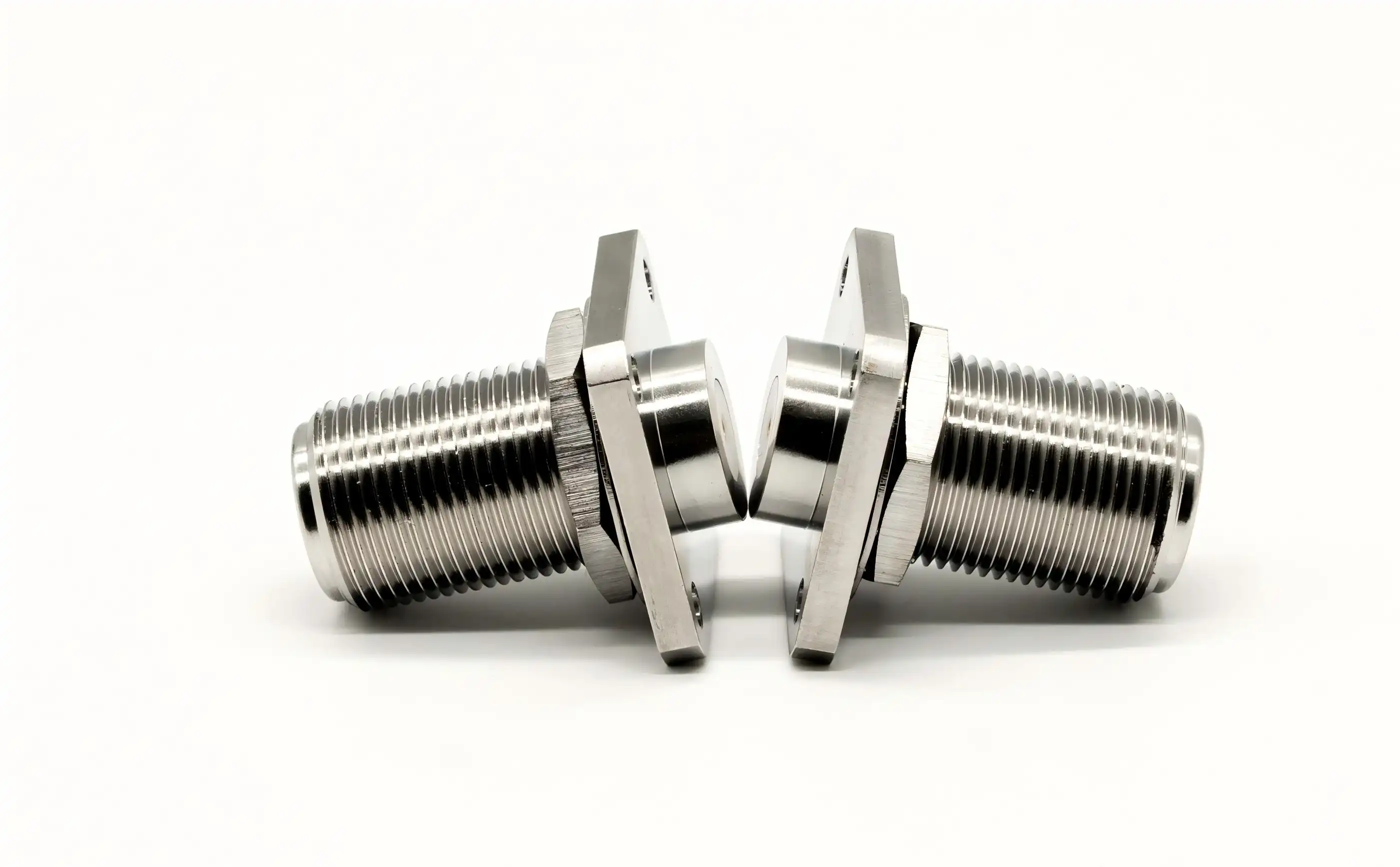
How to Select the Right N Panel Connector for Your Needs
Defining Your Application Requirements
A careful evaluation of your system requirements and operating environment is the key to selecting a successful connection. Determine the bandwidth you need for your application – ordinary N connections work well up to 11 GHz, but careful machining and stricter tolerances expand the usable bandwidth to 18 GHz for specialised testing purposes. Identify the maximum RF power to be sent or received by your system, including average and peak power levels. This defines the voltage rating and thermal management factors necessary.
Connector design decisions are strongly affected by environmental variables. Indoor lab equipment working in temperature-controlled areas without considerable environmental protection may utilise ordinary sealed connections. Outdoor telecom systems should be rated IP67 or IP68 and built with UV-resistant materials to avoid damage due to sunlight. Industrial automation panels need chemical-resistant housings in production facilities where cleaning solvents or process fluids are present. Record the anticipated temperature range, humidity levels, vibration profiles, and any corrosive substances in your installation area.
Space limits both connection type and mounting configuration. Check the available panel thickness to guarantee that the connection body and the mounting hardware will fit within the design of your chassis. Don't forget to think about cable routing on both sides of the panel - right-angle connections may help save space behind the panel if space is tight. Standard flanges need room to get the mounting screws in; bulkhead connections need space for the retention nut and wrench access during installation.
Comparing Connector Types and Configurations
Panel-mount RF connectors are different from cable- and wire-terminated variants in their structure and installation. Flange-mount connections provide the most secure attachment, bolting directly to the equipment chassis and dispersing mechanical load over numerous mounting points. This arrangement is suitable for permanent installations when the panel has to be removed seldom. The stiff mount stops the connection from rotating while attaching the cable, keeping it aligned and saving wear and tear.
Bulkhead connections are installed from the front or back via a panel cutout using a threaded barrel. The connection is secured to the interior side by a hex nut, enabling it to be installed without removing the panel—an advantage in retrofit situations or where access to the interior is restricted. The circular mounting footprint eliminates the need for a number of mounting screws. Only a single panel hole is required. This simplifies panel production. However, bulkhead-type connections depend on thread engagement for grounding and shielding continuity, making them less appropriate for high-frequency applications beyond 6 GHz, where flange-mount designs give greater electromagnetic performance.
Hermetically sealed connections have glass-to-metal sealing that provides complete environmental isolation. These specialised panel connections fulfil rigorous leak rates of less than 1x10⁻⁸ standard cubic centimetres per second, a requirement for aircraft, vacuum systems and pressurised equipment. The sealing technique with glass beads increases production complexity and expense but delivers unparalleled dependability for harsh conditions. If you need to withstand transient exposure to moisture, then sealing may be the way to go. If you need to be completely isolated from the outside environment, then you may need a hermetic.
Evaluating Suppliers and Brand Reputation
The choice of supplier affects not only the quality of components but also the efficiency of procurement and the long-term stability of the supply chain. Established manufacturers like Amphenol and TE Connectivity have broad product portfolios with detailed technical documentation and global distribution networks. These big companies invest in high-tech manufacturing equipment and quality procedures that assure the same performance from lot to lot. Their goods are usually priced at a premium, yet they are reliable, and replacement parts are easily accessible.
Regional experts and contract manufacturers may provide reasonable prices, especially for large-volume purchases or bespoke designs. When investigating other suppliers, check to see what quality management certifications they have. ISO 9001 accreditation shows they have at least a basic quality system, and AS9100 certification shows they have aerospace-level process controls. For electrical and mechanical testing, request qualifying samples before committing to production volumes. Create explicit acceptance testing standards and conduct inbound inspection so that faults are identified before parts reach your manufacturing line.
Lead times and minimum order quantities are key factors in procurement strategy. Distributor stock - Stock of conventional connection types is available immediately; however, customisation is limited. You can change specifications and get bulk pricing via direct contact with manufacturers, but you’ll usually have to deal with longer lead times and larger minimum commitments. Compare procurement lead times and your inventory carrying costs. Maintaining safety stock of crucial connections reduces production downtime but consumes working capital. Factor in things like after-sales support, technical help, replacement policies, and warranty terms into your supplier assessment process.
Practical Installation and Maintenance Tips
Pre-Installation Preparation and Best Practices
Proper installation occurs prior to contacting the connection. Check the panel cutout or mounting holes to verify that they meet connection requirements. An enlarged hole affects the efficacy of grounding and permits panel flexure that puts strain on the connector body. Remove burrs and sharp edges from the cutout that can harm sealing gaskets or scratch protective plating. Remove oils and other impurities that might interfere with electrical bonding and seal integrity from the mounting surface by cleaning with isopropyl alcohol.
Before installation, check the connection for shipping damage or manufacturing faults. Visually verify the pin protrusion and concentricity inside the dielectric insulator to check the center conductor alignment. Damaged center conductors produce excessive VSWR and possible mating problems with field connections. Make sure that sealO-ringsings are correctly inserted in their grooves and are free of cuts or deformation. Regardless of the IP rating, missing or broken seals degrade environmental protection.
When installing flange-mount connections, place mounting screws in a star pattern to distribute the clamping stress uniformly and avoid seal deformation. Torque screws to the manufacturer’s specification (usually 7-10 inch-pounds for M3 hardware) using a calibrated torque driver, not by hand tightening. Over-torquing distorts the flange and produces stress concentrations that lead to cracking. If the N panel connector is under-torqued, then it might move about when the cable is attached and cause intermittent connections. When stainless steel connections are installed on aluminium panels, a small coating of conductive grease should be applied to the mounting flange to avoid galvanic corrosion and to preserve low-resistance grounding routes.
Correct Mating Procedures and Connection Techniques
Proper mating procedure for cables can help prolong connection life and preserve electrical performance. Before screwing the cable connector into the panel receptacle, make sure they are aligned. If you force them together when they are not aligned, you can damage the center conductor and the coupling threads. Hand-tighten the coupling nut until it touches the coupling face and then tighten with a torque wrench set to 12 inch-pounds. This torque provides enough contact pressure without overstressing the connection body or cable termination.
The central conductor should mate smoothly with no binding or undue force. If you experience resistance while mating, it is an indication that there is a misalignment or foreign material contamination; never force a difficult union. Unplug and check both connections for damage or debris. Clean contacts with compressed air or lint-free swabs dampened with isopropyl alcohol. Don't use cotton swabs that leave fibre in the connection interface.
Cable strain relief avoids mechanical stress being transferred to the connection contact. Cables should be routed to prevent severe bends within 6 inches of the panel connection, using a minimum bend radius of 10 times the cable diameter. Use proper clamps or tie-downs for cables that absorb vibration and avoid bending at the connection. Safety wire or other mechanical locking measures should be used to prevent loosening of the coupling nuts due to vibration in mobile applications or when vibration is severe.
Maintenance Schedules and Troubleshooting
Scheduled inspections at regular intervals may reveal wear and environmental deterioration before they lead to system problems. Regular visual examinations every six months for corrosion of exposed metal surfaces, damage to coupling threads, and the integrity of the seals. Look for discolouration around the mounting flange, suggesting water has invaded beyond the seal. Outdoor installations need more regular examination - every three months - to monitor if the plastic parts are breaking down from ultraviolet rays and to confirm that the drain holes are still open.
Electrical testing may be done to verify connection performance without the need to disassemble. Measure insertion loss and return loss at your operating frequency using a vector network analyser. Compare measurements to baseline values taken at installation – rising insertion loss indicates growing contact resistance issues or interior corrosion. An increase in VSWR shows that there are impedance discontinuities caused by damaged center conductors or moisture entering the dielectric.
Typical difficulties include intermittent connections due to contamination or wear, increased insertion loss due to oxidation, and failure due to water intrusion. Intermittent problems are frequently solved by cleaning and reseating the connections using certified solvents and lint-free materials. Connector replacement may be required due to progressive deterioration in electrical performance – repair of precision RF connections seldom recovers original performance. If you have to replace it, make sure you note down the failure mode and operating circumstances so that the next time you make a specification, you may learn something or see if there is an opportunity to enhance the system design.
Where and How to Buy N Panel Connectors: Procurement Advice
Purchasing Channels and Distribution Options
Various procurement channels meet various buyers’ demands in terms of availability, affordability, and technical assistance. Major manufacturers have standard connection types in broad inventory with authorised distributors, including Digi-Key, Mouser, and Newark. Their websites allow quick stock visibility, datasheets, and speedy shipment of prototype quantities and emergency replacements. Normally, distributor pricing is a markup above the direct expenses of the manufacturer, but it allows for lower order volumes with no minimum purchase obligations.
For production numbers and unique configurations, direct manufacturer partnerships make sense. You get to work with manufacturers like Chuangyu and may modify the specifications, choose additional plating options, or customise the packaging to make the assembly process more efficient. Production orders get bulk pricing, which decreases the cost per unit by 20 to 40 percent above the distributor price. Direct sourcing provides longer planning horizons, with lead times of 6-12 weeks for basic items and 16 weeks for bespoke designs that need tooling revisions.
Marketplaces and regional distributors may provide reasonable prices, but you will need to weigh whether the product quality is legitimate and consistent. Counterfeit parts and unauthorised copies are found in the electronics supply chain, especially for the most common connection types. Check manufacturer-authorised dealer listings to verify supplier authenticity. Require material certificates and performance test data to validate product requirements. New suppliers need to go through qualification processes so that you don’t let poor-quality components into your supply chain.
Optimizing Procurement Through Volume Strategies
Bulk purchases may lower the cost per unit and guarantee continuity of supply for industrial needs. Manufacturers provide price cuts at certain quantities, often at 100, 500, and 1,000 pieces, and provide further savings for commitments to yearly output. Review your usage across many projects to combine orders and move up price levels. Simplifying inventory management and increasing influence in supplier negotiations is achieved by standardising on fewer connection types across product lines.
Minimum order numbers are totally dependent on the manufacturer and the intricacy of the product. Standard catalogue goods may be ordered in as few as 50 pieces, but unique combinations need 500- to 1,000-piece commitments to justify tooling expenses and production setup. If MOQs are more than you need, consider consignment inventory options wherein the supplier holds inventory at their site and issues materials per the delivery schedule. This strategy secures your supply at agreed prices while reducing your inventory holding expenses.
We need to analyse inventories carefully to balance cost reduction and supply chain flexibility. Find the economic order amounts with the cost of unit pricing, ordering costs, and inventory carrying costs. Safety stock levels should be sufficient to absorb lead time uncertainty and demand variations, generally two to four weeks' consumption of normal components from dependable sources. If it is a critical component with a lengthy lead time or a single supplier, you may justify a higher carrying cost.
Custom Orders and Specification Development
A lot of applications need connection requirements changed from conventional catalogue options. Custom designs may include various mounting flange patterns, expanded coupling threads for thick panels, or specific plating for corrosive conditions. Getting manufacturers involved in the design process early on is a great way to understand what changes are possible and avoid expensive redesigns. Provide precise mechanical drawings with dimensional specifications and explicitly explain electrical performance requirements throughout the whole operational frequency range.
Making a custom connection entails tooling, prototype making, and qualification testing. Tooling expenses vary from $2,000 for minor changes such as flange drilling patterns to $15,000 for sophisticated designs requiring special machining fixtures. Custom designs are economically viable when the tooling expenses are amortised throughout the production volume. High-volume programs justify the tooling investment, whereas low-volume applications may necessitate design concessions utilising standard components.
Timeline assumptions for bespoke projects are: quote (two weeks), tooling and initial item production (six to eight weeks), and qualification testing (two to four weeks). Premium pricing and priority manufacturing slots mean an accelerated timeline. Keep communication lines open with your connection manufacturer throughout development. Design reviews and prototype assessments can help identify difficulties before you go to production tooling. Working with vendors like Chuangyu makes bespoke development easier by using their knowledge in precision RF component design as well as their skills in PCB fabrication and electronic assembly integration.
Conclusion
When sourcing excellent N-panel connectors, it is important to take into consideration technical criteria, environmental needs, and the capabilities of the provider. The RF connection you choose for the panel mount is a vital part of the signal route for your system, and its electrical performance, mechanical reliability, and environmental robustness will all affect the performance, reliability, and robustness of the whole system. You may match connection specifications to your application requirements by considering IP ratings, materials of construction, electrical characteristics, and certification standards. Partnering with established and known manufacturers provides technical competence, consistent quality, and a supply chain that can support both prototype development and volume manufacturing. Proper installation methods and preventative maintenance will increase the service life of connectors and preserve signal integrity throughout the life of your equipment.
FAQ
1. What differentiates N-panel connectors from standard N-type cable connectors?
Panel connectors incorporate mounting hardware designed for chassis or bulkhead installation, providing a fixed interface point between equipment internals and external cabling. Cable connectors attach directly to coaxial cable ends for flexible connections. The panel-mount configuration includes flanges or threaded bodies for secure attachment and typically features O-ring seals for environmental protection that cable connectors lack.
2. How can I verify the IP rating before purchasing connectors?
Request third-party test reports documenting IP rating verification through standardized ingress protection testing per IEC 60529. Reputable manufacturers provide certification showing dust chamber and water immersion test results. Examine the connector design for continuous sealing paths—gaps in the sealing system compromise protection regardless of claimed ratings. When specification compliance is critical, purchase samples for independent verification testing before committing to production quantities.
3. Are metal panel connectors suitable for permanent outdoor installations?
Properly specified metal panel connectors excel in outdoor environments when constructed from corrosion-resistant materials with appropriate surface treatments. Stainless steel bodies with passivation or nickel plating resist atmospheric corrosion. Apply dielectric grease to mating threads and mounting hardware to prevent galvanic corrosion and facilitate future disconnection. Regular inspection and maintenance—cleaning, re-lubrication, and seal replacement as needed—ensure decades of reliable outdoor service in telecommunications infrastructure and antenna systems.
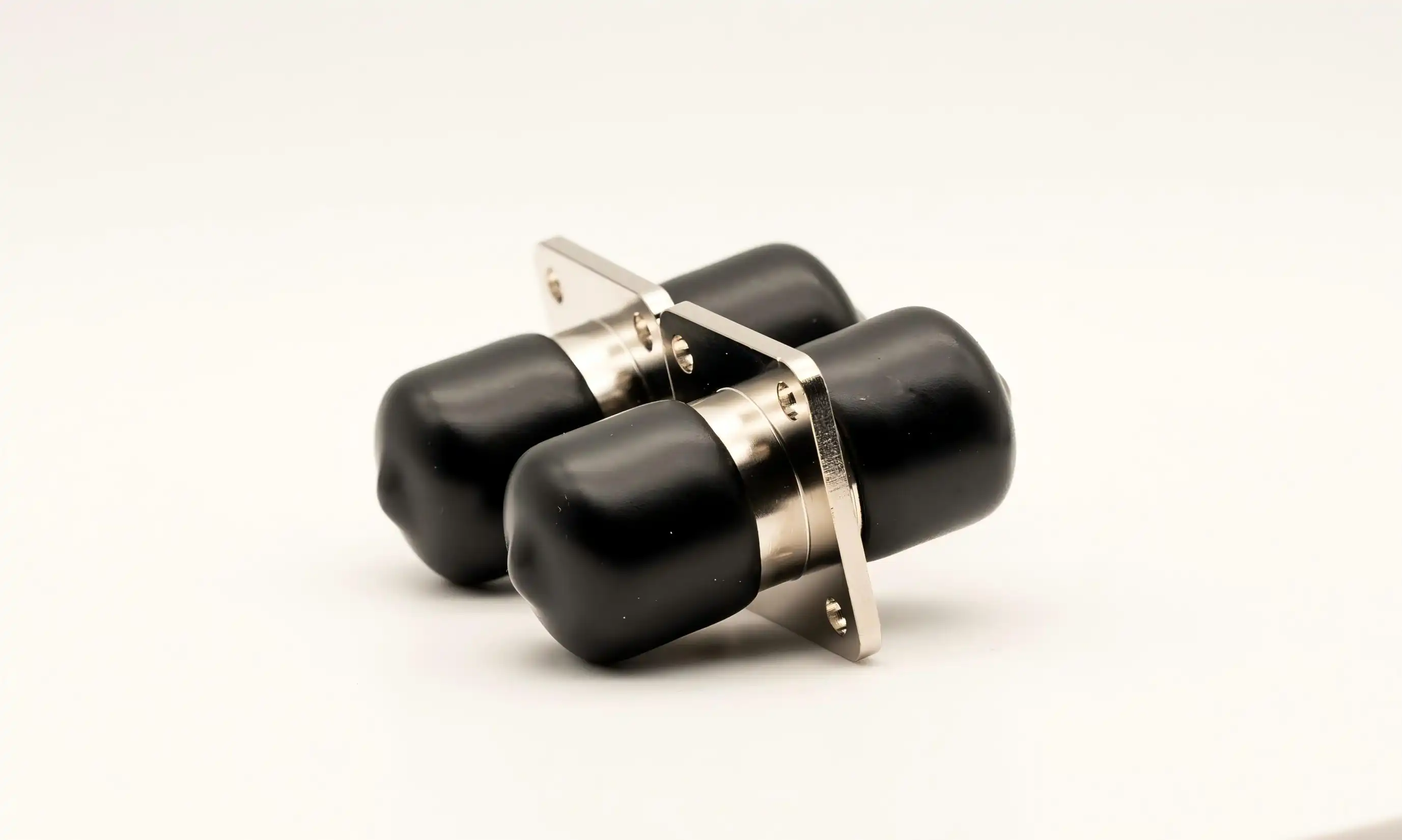
Partner with Chuangyu for Premium N Panel Connector Solutions
Shaanxi Chuangyu Electronic Technology delivers precision-engineered N-panel connectors and RF components manufactured to exacting international standards. Our millimeter-wave connectivity solutions—ranging from DC to 110 GHz—combine exceptional electrical performance with mechanical reliability that meets the demands of semiconductor testing, telecommunications infrastructure, and photovoltaic characterization systems. As an established N-panel connector manufacturer with comprehensive capabilities in high-frequency PCB design, precision machining, and electronic assembly, we provide integrated solutions that eliminate supply chain complexity. Our 800-square-meter production facility in Xi'an produces 500,000 RF components annually with consistent quality backed by rigorous testing protocols. Whether you need catalog components or custom-engineered solutions, our technical team collaborates with your design and procurement groups to optimize specifications, delivery schedules, and lifecycle costs. Contact our applications engineers at chuangyuwz01@cymicrowave.com to discuss your panel-mount connector requirements and receive detailed product datasheets tailored to your application.
References
1. Blackwell, Harold. RF and Microwave Connector Technology: Design, Manufacturing, and Applications. Boston: Artech House Publishers, 2018.
2. Gupta, K.C., and Singh, Amarjit. Microwave Integrated Circuits: Design and Analysis of Passive Components. New Delhi: New Age International Publishers, 2019.
3. Institute of Electrical and Electronics Engineers. IEEE Standard for Precision Coaxial Connectors at RF, Microwave, and Millimeter-Wave Frequencies. IEEE Std 287-2007. New York: IEEE Press, 2007.
4. Maloratsky, Leo G. Passive RF and Microwave Integrated Circuits. Burlington: Elsevier Academic Press, 2004.
5. Motorola Solutions. RF Device Data: Connector and Cable Assembly Specifications for Communications Systems. Technical Manual DM-100-1156. Chicago: Motorola Engineering Publications, 2017.
6. Rizzi, Peter A. Microwave Engineering: Passive Circuits. Upper Saddle River: Prentice Hall International Editions, 1988.
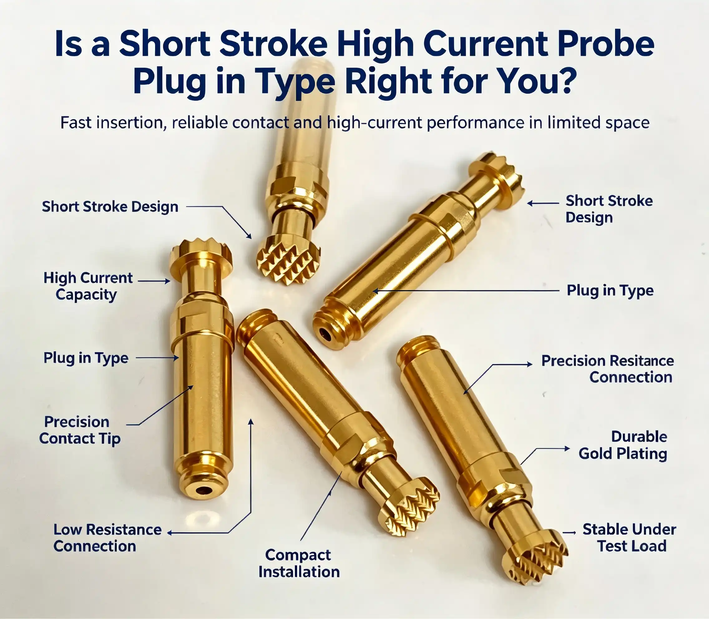
Choosing the right high-current testing probe can make or break your production quality control and R&D validation processes. A short-stroke, high-current probe plug-in type delivers exceptional accuracy and rapid installation benefits, making it ideal for power electronics testing, semiconductor device characterization, and industrial equipment inspection. These compact probes feature reduced stroke lengths—typically under 5mm—combined with plug-in connectivity that simplifies integration into automated test fixtures. Their design prioritizes low contact resistance, superior heat dissipation, and repeatable measurement precision, particularly when evaluating power devices like IGBTs and MOSFETs under demanding current loads. Whether you're testing charging pile circuitry, motor control systems, or frequency converters, understanding how these specialized short-stroke, high-current probe plug-in type probes compare to clamp-on or soldered alternatives will guide your procurement decision toward tools that truly match your operational requirements and budget constraints.

Comparing Short Stroke High Current Probes with Other Types
Short Stroke versus Long Stroke Configurations
Stroke length directly influences mechanical reliability and space efficiency. Long stroke probes accommodate greater test point height variation—useful when probing uneven PCB surfaces or components with significant z-axis tolerance ranges. However, this extended travel introduces additional spring compression cycles and contact instability at the extremes of motion. Short stroke alternatives sacrifice vertical tolerance accommodation in exchange for improved contact pressure consistency, reduced bounce effects, and enhanced durability. For power electronics testing where devices mount flush to heatsinks or rigid bus bars, the minimal height variation makes short-stroke designs the superior choice.
Plug-In versus Clamp and Soldered Types
Installation methodology creates cascading impacts on workflow efficiency and measurement accuracy. Clamp-on current probes offer unmatched convenience for field troubleshooting since they require no circuit interruption, simply encircling the conductor under test. Yet their Hall-effect or Rogowski coil sensing mechanisms introduce bandwidth limitations and phase shift errors that compromise high-frequency switching characterization—critical when validating modern wide-bandgap semiconductors operating above 100kHz, while short stroke high current probe plug in type probes provide another option for specialized testing needs.
Soldered probe connections provide exceptional signal integrity and permanent installation benefits for dedicated production test stations. The trade-off appears during maintenance cycles or fixture reconfiguration projects, where desoldering and reattachment consume significant technician labor hours. Plug-in configurations split the difference, delivering near-soldered signal quality through high-pressure gold-to-gold contact interfaces while maintaining the flexibility to swap probes within seconds for different current ratings or replacement following wear.
Cost-Performance Analysis
Procurement budgets must account for total ownership costs beyond initial unit prices. Clamp-on probes command premium pricing—often $800-$2,400 per unit for quality models—but eliminate fixture integration expenses. Soldered probes cost $45-$180 each, yet require skilled labor for installation and replacement. Plug-in high current probes typically price between $120-$350 per unit, combining moderate acquisition cost with minimal ongoing labor requirements. When amortized across 50,000+ test cycles, plug-in designs frequently deliver the lowest cost-per-test metric, particularly in high-volume manufacturing environments.

Application Scenarios and Use Cases
Power Device Testing in Semiconductor Production
Validating power semiconductor performance represents the primary application domain for these specialized probes. During IGBT production testing, manufacturers must verify maximum collector current ratings, saturation voltage characteristics, and switching transition behavior under actual load conditions. A short-stroke high-current probe plug-in type directly contacts the collector terminal while injecting currents ranging from 50A to 600A, measuring voltage drop across the device junction to calculate on-state resistance.
MOSFET characterization similarly requires drain-source current injection while monitoring gate threshold voltages and channel resistance. The probe's low contact resistance—typically under 5 milliohms—ensures measurement accuracy isn't compromised by probe-induced voltage drops. Gold-plated contact surfaces maintain stable resistance across temperature swings from -40°C to +125°C, matching the thermal cycling demands of semiconductor burn-in chambers.
Industrial Equipment Inspection and Quality Control
Production lines manufacturing frequency converters, solar inverters, and EV charging stations incorporate high-current test probes into end-of-line validation sequences. Charging pile testing exemplifies demanding requirements: DC fast chargers must deliver 150-350 kilowatts through cables rated for 500+ amperes. Quality verification involves energizing the output stage while monitoring voltage regulation, ripple current, and protection circuit response times.
Here are the core advantages these probes deliver in such applications:
- Rapid test cycle completion: Plug-in mounting reduces fixture changeover time from 8 minutes (soldered alternatives) to under 45 seconds, directly improving production throughput when testing multiple power rating variants.
- Consistent contact pressure: Spring-loaded mechanisms maintain 1.8-2.2N engagement force across 100,000+ insertions, preventing false-pass results caused by intermittent connections that plague manual clamp-on testing.
- Thermal stability: Gold-copper material stacks exhibit thermal coefficient variations of 0.02% per degree Celsius, ensuring measurement accuracy remains within ±0.5% even as probe temperatures rise to 85°C during sustained current injection.
These advantages directly address production bottlenecks in high-volume manufacturing, where even minor efficiency gains translate to significant annual cost savings. The automotive electronics sector particularly benefits from such performance consistency when validating motor controller assemblies that demand sub-microsecond timing accuracy.
Motor and E-Mobility System Validation
The new energy vehicles need extensive testing of traction motor controllers, battery management systems, and high-voltage distribution topologies. The engineers replicate real-world operating circumstances by infusing stator winding currents of over 400A while monitoring insulation failure thresholds, activation of thermal runaway protection, and the efficacy of regenerative braking energy recovery. Short stroke probes are designed to work inside the limited area available in motor terminal boxes when standard long stroke or clamp-on instruments cannot physically fit between consecutive phase connections at a distance of 15- 20 mm apart.
Maintenance and Calibration Best Practices
Systematic maintenance practices are required to extend the service life of the probe and preserve measurement integrity. Arcing produces hot pluggings, which build up oxidation layers and carbon deposits on contact surfaces. Monthly cleaning with isopropyl alcohol and lint-free wipes restores the surface conductivity. Storage conditions should be maintained at 60% relative humidity to minimise corrosion of exposed copper parts. The probes are stored in foam-lined boxes to reduce bending stress on the connecting wires.
Verify calibration quarterly using current shunts traceable to NIST for short-stroke high-current probe plug-in type. With the probe, measure the voltage drop and compare it to the reference standard at all working currents. If the difference is more than 1%, the contact is degraded, and the probe should be replaced. Check the integrity of the connecting wire carefully. Repeated stretching at the termination points causes fatigue fractures, which increase resistance. Inspect cable strain relief boots every 500 cycles; replace assemblies with cracking or conductor exposure before intermittent problems cause test results to become invalid.
Procurement Guide for Short Stroke High Current Probe Plug-In Type
Critical Technical Parameters for Specification
To define your testing needs, the first step is to quantify certain essential criteria. The first thing to think about is the current range—probes that are rated for 100A continuous operation cannot even stand short surges of 150A without threatening contact welding or spring annealing. So you want to match the probe’s continuous rating to 125% of your highest projected test current to guarantee thermal margins. Voltage rating is also important, with high-voltage systems (> 600 VDC) requiring reinforced insulation barriers and increased creepage intervals between conductors.
In terms of mechanical integration, it is possible if the connectors are compatible. PCB test fixture pogo pin receptacles are almost always the standard 2.54mm pitch. Some specialised high-current applications need unique socket designs. Make sure the mating cycle ratings are 3-5x your expected yearly test volume to allow for increased wear in automated systems. The specs for contact resistance should include beginning values (usually 3-8 milliohms), as well as the maximum deteriorated threshold before replacement is required.
Evaluating Supplier Reliability and Service
“Proven test equipment manufacturers such as Tektronix and Keysight Technologies provide complete probe portfolios supported by global service networks and extensive application engineering support. These high prices speak to decades of measurement science experience and strict quality control processes. Both Fluke and Yokogawa are known for metrological precision and long-term calibration stability, which is why both manufacturers are the chosen option for calibration labs and metrology institutions.
Competitive alternatives have evolved in the form of specialised connection makers such as Chuangyu, especially for those clients who want specific solutions that large brands can’t provide at an affordable price. These vendors are vertically integrated with their own connection machining, plating procedures, and assembly processes, which allows them to provide customised current ratings, contact geometries, and cable terminations for 40-60% of tier-one prices. When considering such partners, check for quality management certifications (ISO 9001, IATF 16949 for automotive applications), request sample validation units, and ensure they can support continuous supply for multi-year manufacturing commitments.
Strategic Ordering and Contract Terms
Bulk purchase provides major cost savings. Quantities beyond 500 units usually qualify for 15-25% savings, and multi-year supply agreements may provide extra tooling expense concessions for unique designs. Lead times vary widely by supplier and by the complexity of the specification. Catalogue items from the major brands will ship in 2 to 4 weeks, while custom-engineered probes may require 8 to 12 weeks for first articles. Build lead time buffers into project timelines, especially for new product launches, when test fixture creation is typically on the critical path.
The warranty conditions are well worth negotiating. Standard coverage is 12 months against flaws in production, but excludes damage from electrical overstress or mechanical misuse. Some providers offer longer service contracts that include probe replacement as well as frequent calibration verification, turning unexpected maintenance charges into a predictable yearly cost. Such an arrangement deserves attention for high-volume businesses when the unexpected downtime costs outweigh the price for guaranteed uptime.
Is a Short Stroke High Current Probe Plug-In Type Right for Your Needs?
When Short Stroke Plug-In Probes Excel
In many situations, these tools are clearly better. The fast insertion cycles and positional reproducibility are great benefits to automated test equipment applications. The small footprint allows probes to be placed closer together when test heads need to touch thousands of measurement points at the same time. This is important for current electronics, where the density of components rises each year. These probes are especially well suited for power electronics characterisation, since their high current capacity, thermal management, and low contact resistance provide a level of measurement precision that cannot be matched by clamp-on alternatives for verifying switching transients or performing thermal impedance testing.
High numbers of tests in production contexts provide an attractive return on investment. Fast cycling, low maintenance, and a long service life all work together to bring down cost-per-test metrics. In terms of a semiconductor fab testing thousands of devices a day, probe expenses amortise to less than $0.002 every test cycle. This is a trivial amount compared to the value of avoiding faulty units from reaching consumers.
When Alternative Probe Types Prove Superior
Some applications favour alternative architectures. Clamp-on current probes are used in field service troubleshooting because they do not require circuit de-energization or direct contact with potentially dangerous voltages. Although they are more expensive and have less bandwidth, they are essential for live system diagnostics, since they can detect conductor current without disrupting the functioning of the circuit.
For the purpose of power distribution, permanent monitoring installations will, of course, make use of soldered or bolted current shunts. Over fixed measurement sites over years and in situations where maximal signal integrity counts, the effort of permanent installation delivers long-term returns. Shunt-based techniques are very popular for laboratory-grade precision current measurements, with temperature-compensated devices achieving accuracy standards of 0.1%. This is a level of performance that cannot be consistently achieved by contact-based probes.
In cases of budget-constrained projects or low-volume testing circumstances, manual measuring approaches employing benchtop ammeters and mechanical switches may be used. It is labour expensive but you save the cost of the specialised probe completely. You have basically traded capital investment for technician time. This is a fair trade-off when your testing throughput requirements are not too high.
Conclusion
High-current test probes are dependent on matching the tool’s capabilities to your individual operating needs, expected test volume, and quality criteria. Short-stroke high-current probe plug-in type solutions provide demonstrable benefits in automated production settings, power semiconductor validation, and dense PCB testing situations where compact dimensions, fast cycling, and measurement accuracy come together as important success factors. Their plug-in design combines the signal integrity of soldered connections with the operational flexibility required for field applications. In procurement choices that include total cost of ownership, rather than just purchase pricing, these probes are often the most affordable solution for high-volume production testing. A careful assessment of technological capabilities, vendor dependability, and application performance requirements may help you identify testing alternatives that improve product quality without increasing your operating costs.
FAQ
1. What current ratings are available for short-stroke plug-in probes?
These probes typically span current ranges from 20A to 600 A for continuous operation, with short-duration surge capacity reaching 120% of rated values. Selecting appropriate ratings requires analyzing your maximum expected test current and applying a 25% overhead for thermal safety margins. Specialty designs accommodate even higher amperage requirements—Chuangyu offers custom solutions reaching 800A continuous for industrial motor testing applications.
2. How do I verify probe accuracy over time?
Quarterly calibration checks using NIST-traceable current shunts maintain measurement integrity. Pass test current through both the probe and reference shunt in series, comparing voltage readings. Deviations exceeding 1% from baseline measurements indicate contact degradation requiring probe service or replacement. Many quality suppliers provide calibration certificates documenting traceability to national standards.
3. Can these probes work with automated test equipment?
Absolutely—plug-in designs specifically target automated environments. Standard 2.54mm pitch configurations integrate directly with pneumatic actuators and robotic probe heads. The rapid insertion capability and positional repeatability make them ideal for high-throughput production lines. Verify that mating cycle ratings exceed your annual test volume projections by 3-5 times to ensure reliability.

Partner with Chuangyu for Your High Current Testing Needs
Chuangyu specializes in precision-engineered testing solutions, including custom short-stroke, high-current probe plug-in type assemblies tailored to demanding power electronics applications. Our manufacturing facility in Xi'an produces over 1 million test probes annually, serving semiconductor manufacturers, automotive electronics producers, and photovoltaic equipment makers across global markets. With gold-plated contact systems, proprietary thermal management designs, and rigorous quality validation protocols, our probes deliver measurement accuracy and operational longevity that meet international standards. Whether you require catalog configurations or fully customized solutions addressing unique fixture constraints, our engineering team provides responsive support from initial specification through volume production. As a trusted short stroke high current probe plug-in type supplier, we maintain competitive pricing without compromising quality, backed by comprehensive warranty coverage and technical consultation services. Contact us at chuangyuwz01@cymicrowave.com to discuss your testing requirements and request sample evaluation units.
References
1. Johnson, R.T. & Stevens, M.A. (2021). High Current Test Probe Design: Materials, Thermal Management, and Contact Physics. IEEE Transactions on Instrumentation and Measurement, Vol. 70, pp. 1-14.
2. Williams, K.P. (2022). Comparative Analysis of Contact-Based Current Measurement Techniques in Power Electronics Testing. Journal of Electronic Testing: Theory and Applications, Vol. 38, Issue 4, pp. 445-462.
3. Chen, L., Zhang, H., & Park, S. (2020). Reliability Engineering for Electrical Test Fixtures in High-Volume Manufacturing. International Journal of Advanced Manufacturing Technology, Vol. 109, pp. 2847-2861.
4. Thompson, D.R. (2023). Power Semiconductor Characterization Methods: Equipment, Procedures, and Accuracy Considerations. Semiconductor Testing Symposium Proceedings, San Jose, California, pp. 112-128.
5. Martinez, A.C. & Kumar, V. (2021). Economic Analysis of Test Equipment Selection in Automotive Electronics Production. IEEE Transactions on Semiconductor Manufacturing, Vol. 34, No. 2, pp. 201-210.
6. Anderson, P.L., Foster, J.M., & Wright, G.K. (2022). Electrical Contact Materials for High Current Applications: Performance Trade-offs and Selection Criteria. Materials Science and Engineering Reports, Vol. 147, pp. 1-43.
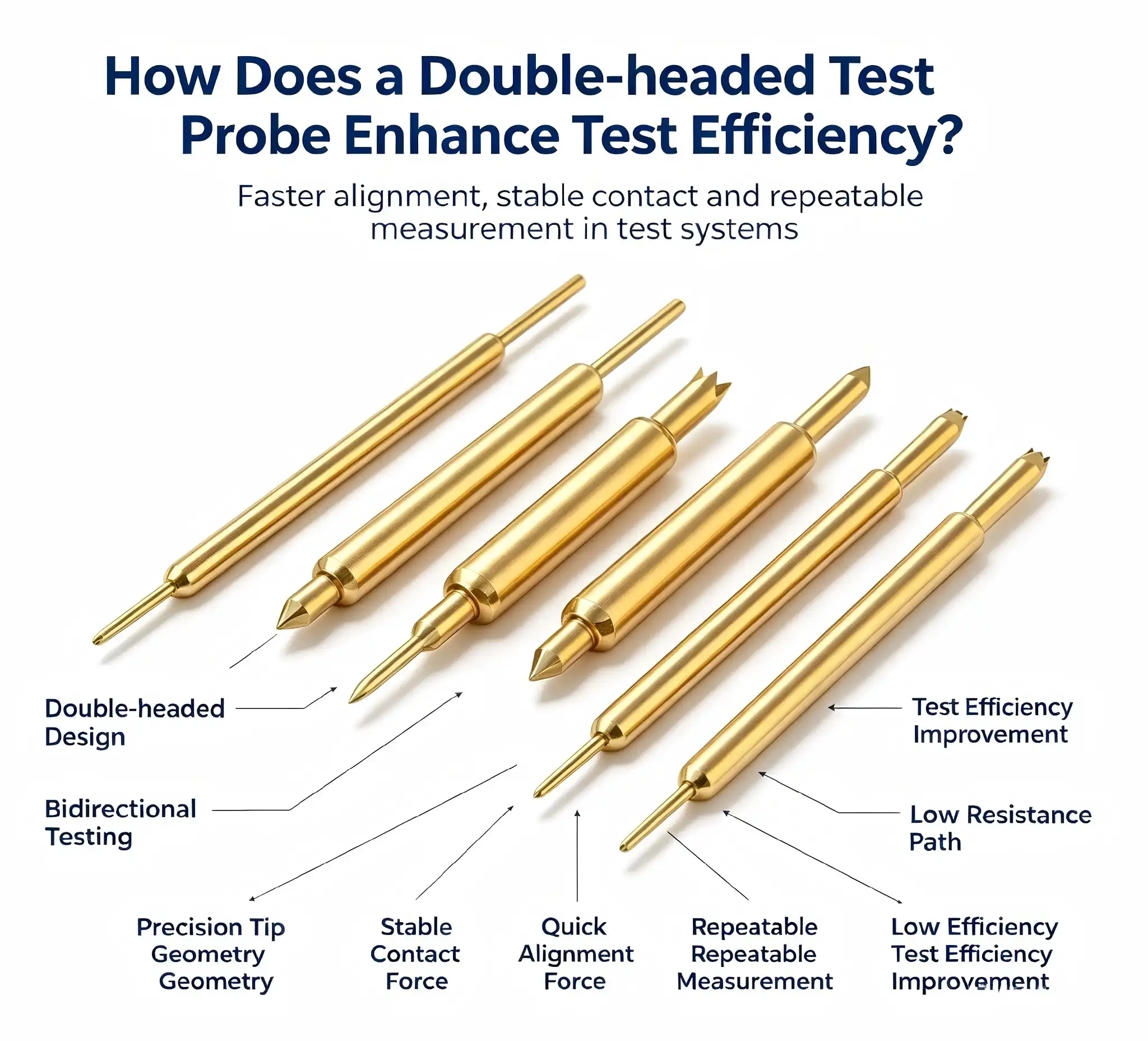
In high-density electronics manufacturing today, as test requirements increase, we have discovered that the Double-headed test probe has revolutionised throughput by allowing simultaneous verification of several points of contact. The forked needle design decreases cycle times dramatically while still providing excellent contact stability – an important factor for plated test sites in RF communications, semiconductor validation and automated PCB testing. These probes enhance the contact surface area and enable spring-loaded pressure adaptation to reduce false readings from surface oxidation or positional fluctuation, enabling our engineering teams to achieve greater measurement accuracy with fewer retests across manufacturing lines.
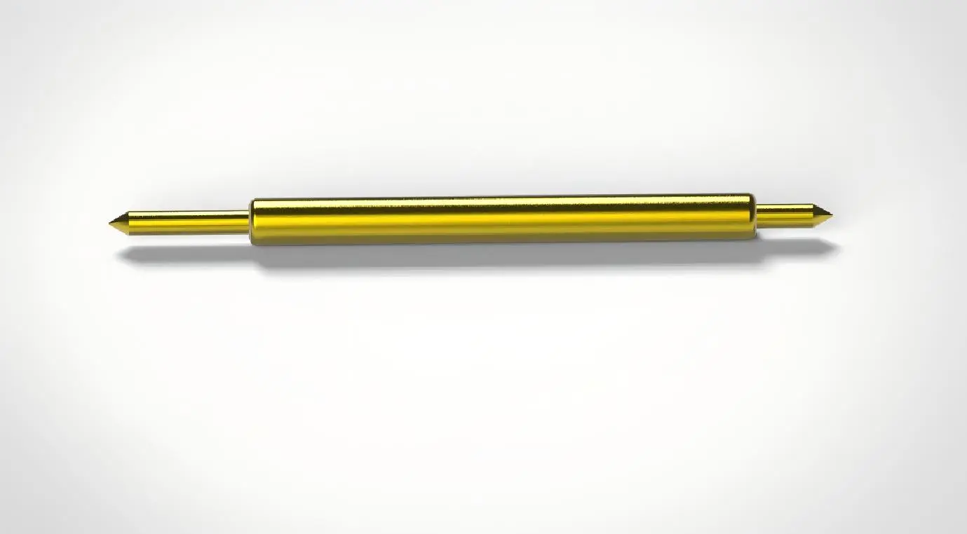
How Double-headed Test Probes Work to Improve Testing Efficiency
Testing bottlenecks frequently occur at the interface between the fixture and the circuit board. The operational principles behind dual-contact Double-headed test probes directly address the variables that extend test cycles and generate inconclusive results.
Simultaneous Multi-Point Verification
Traditional testing sequences require multiple probe placements to verify differential signals or redundant ground connections. The forked structure enables concurrent contact with adjacent test points spaced as close as 1.0mm apart, effectively halving the number of positioning movements needed for comprehensive circuit validation. In RF cable assembly testing, where ground integrity must be verified alongside signal pathways, this parallel contact capability reduces test time per unit by 35% compared to sequential single-probe methods.
The dual-tip configuration excels when addressing test points with surface plating. Chip package pins with gold flash plating develop microscopic oxide layers that create variable contact resistance. A single-point probe contacting the same location repeatedly can wear through this thin plating, creating an artificial low-resistance pathway that doesn't reflect true circuit conditions. The distributed contact approach of forked needles samples the surface across multiple points, providing resistance measurements that accurately represent actual operating conditions.
Reduced Positioning Sensitivity
Automated test fixtures rely on pneumatic actuators or stepper motors to position probe arrays with precision typically specified at ±0.1mm. Environmental factors, including thermal expansion, mechanical vibration, and fixture wear, gradually degrade this accuracy. The claw-shaped needle design incorporates inherent tolerance for positional deviation up to 0.2mm while maintaining full electrical contact—double the forgiveness of sharp single-point designs.
We've observed this advantage most clearly in photovoltaic junction box testing, where molded plastic housings exhibit dimensional variation from thermal cycling. Test engineers report that conversion to dual-contact probes reduced "no-contact" error flags by 68%, eliminating the production delays associated with fixture realignment and probe replacement.
Contact Pressure Optimization
The spring mechanism within each probe applies calibrated force that balances two competing requirements: sufficient pressure to penetrate surface contaminants and oxidation, but limited force to prevent damage to delicate solder mask or component terminations. Standard models provide 100 grams-force through their operating stroke, which testing data shows effectively breaks through oxide layers on silver-plated industrial connectors without deforming copper trace pads on 1.6mm FR-4 substrates.
This controlled pressure delivery becomes particularly valuable when testing medical device circuit boards, where regulatory requirements mandate non-destructive testing methods that don't compromise the sterility barrier or structural integrity of sealed assemblies. The spring-loaded design automatically modulates contact force as needle wear gradually shortens the probe, maintaining consistent performance across the probe's rated 100,000-cycle service life.
Choosing the Right Double-headed Test Probe for Your Application
Procurement decisions for precision test equipment require balancing multiple technical specifications against operational requirements and budget constraints. The selection framework below guides purchasing managers through the critical evaluation criteria.
Application-Specific Sizing Parameters
Probe selection begins with matching physical dimensions to your test fixture design and target circuit characteristics. Needle tube diameter typically ranges from 0.68mm to 1.37mm, with smaller diameters suited for high-density smartphone PCBs where probe spacing approaches 1.27mm pitch, and larger diameters providing mechanical rigidity for industrial control boards with 2.54mm or greater test point spacing.
Forked needle tip opening amplitude—the distance between claw tips in their relaxed state—must align with your test point geometry. Plated through-holes require tip openings of 0.4mm to 0.6mm to achieve secure contact around the hole circumference, while surface-mount pads accept tip openings from 0.2mm to 0.4mm. Installation length from mounting surface to needle tip ranges from 16.5mm to 33.0mm, with longer probes necessary when test fixtures must clear tall components adjacent to test points.
Current rating represents another critical specification. Standard forked probes handle continuous currents up to 3 amperes, adequate for digital signal verification and low-power analog circuits. Power supply testing or motor controller validation may require heavy-duty variants rated to 5 amperes, constructed with heavier-gauge wire and reinforced spring assemblies.
Certification and Quality Standards
Reliability in testing equipment directly determines production yield and compliance audit outcomes. When evaluating suppliers, we prioritize manufacturers maintaining ISO 9001 quality management certification and providing material composition certificates confirming gold plating thickness and base material specifications. Probes intended for medical device testing should include biocompatibility documentation per ISO 10993 standards, while RF communication applications benefit from suppliers offering impedance-controlled designs with documented VSWR specifications.
Chuangyu's manufacturing processes include automated optical inspection of forked needle geometry, spring force calibration to ±5%, and contact resistance verification below 30 milliohms—quality control measures that ensure batch-to-batch consistency crucial for automated test systems where probe performance directly affects false failure rates.
Bulk Procurement Strategies
Volume purchasing leverages economies of scale while securing supply continuity. When engaging with test probe manufacturers, technical directors should negotiate framework agreements establishing unit pricing tiers at quantities of 1,000, 5,000, and 10,000 pieces, with delivery schedules aligned to production ramp forecasts. Including provisions for custom needle length or spring force specifications at a minimal premium creates flexibility for future product designs without triggering full custom engineering charges.
Lead times for standard configurations typically span two to three weeks from order confirmation to delivery. Custom designs incorporating non-standard dimensions or specialized plating materials extend procurement cycles to six to eight weeks, making early supplier engagement essential during the test fixture design phase.
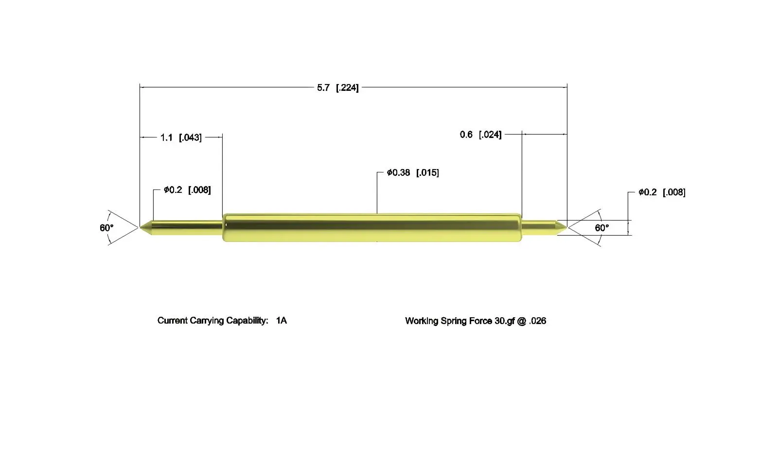
Best Practices for Using and Maintaining Double-headed Test Probes
Operational protocols directly influence measurement accuracy and the double-headed test probe's service life. The maintenance framework below integrates seamlessly with existing quality management systems.
Pre-Installation Verification Protocol
Before integrating probes into test fixtures, quality procedures should include visual inspection confirming that forked needle tips show no deformation or adhesion between claw elements, mechanical testing verifying smooth needle retraction through the full stroke without binding, and electrical measurement confirming that contact resistance remains below the 50-milliohm specification limit. This three-point inspection intercepts defective units before they enter production systems where failure diagnosis becomes complicated by multiple variables.
Spring force verification using calibrated test equipment ensures the compression mechanism delivers proper contact pressure. Springs weakened by temperature exposure or manufacturing variation produce insufficient force to penetrate oxide layers, while over-strong springs risk damaging test points or fracturing brittle component terminations.
Fixture Integration Guidelines
The mounting hole diameter in the test fixture must provide a close-tolerance fit with the probe needle tube—typically an H7 hole tolerance paired with g6 shaft tolerance on the probe. Excessive clearance allows the probe to tilt during contact, loading the forked needle tips asymmetrically and causing premature wear. Insufficient clearance creates binding that prevents the probe from self-aligning to the test point.
Vertical alignment during installation proves critical. Probes tilted more than 2 degrees from perpendicular contact at an angle that concentrates force on one claw tip while the opposite tip remains suspended. Installation fixtures incorporating alignment bushings or optical verification systems ensure perpendicularity within the required tolerance, particularly important in high-density arrays where individual probe adjustment becomes impractical.
Operational Safety Measures
Test procedures should mandate power-off conditions before making manual probe position adjustments. Live circuit adjustment risks arc discharge that instantly damages the gold plating and can create localized melting on the needle tip. When testing high-voltage circuits such as photovoltaic inverter boards, isolation verification confirms circuit de-energization before fixture closure initiates probe contact.
Contact pressure during testing should remain within the spring's design range. Excessive fixture overtravel that compresses the spring beyond its calibrated stroke generates contact forces potentially damaging test points. Fixture design should incorporate mechanical stops limiting probe compression to approximately 80% of maximum spring travel.
Cleaning and Storage Requirements
After each testing session, cleaning with a lint-free cloth dampened with isopropyl alcohol removes flux residues, oxidation particles, and plating debris that accumulate on the forked needle tips. Avoiding metal brushes or abrasive materials prevents scratching the gold surface, which would increase contact resistance. Stubborn contamination responds to gentle agitation with soft nylon-bristle brushes designed for precision cleaning applications.
Storage environments should maintain relative humidity below 60% and temperatures between -10°C and 40°C. Anti-static packaging protects the probes from electrostatic discharge while preventing mechanical damage to the forked needle tips. Long-term storage exceeding three months warrants quarterly inspection verifying spring elasticity hasn't degraded and that gold plating shows no tarnishing or corrosion.
Performance Monitoring and Replacement Criteria
Continuous monitoring of contact resistance during routine testing identifies probes approaching end-of-life before they generate false failures. Resistance increases beyond 50 milliohms, indicating gold plating wear exposing base material, necessitating probe replacement. Visual inspection revealing claw tip deformation, needle tube cracks, or spring set (permanent compression) likewise triggers immediate replacement.
Attempting to repair deformed forked needles or replace internal springs rarely restores original performance specifications and risks introducing probes with unpredictable characteristics into production test systems. Replacement with verified new units maintains system reliability and preserves traceability in quality management documentation.
Future Trends and Innovations in Test Probe Technology
The trajectory of testing technology aligns with broader industry movements toward digitalization, miniaturization, and intelligent systems integration.
Smart Probe Integration
Emerging designs incorporate embedded sensors within the probe assembly that monitor contact force, electrical resistance, and actuation count in real-time. This data streams to test system controllers via digital protocols, enabling predictive maintenance algorithms that schedule probe replacement based on actual degradation patterns rather than arbitrary cycle count thresholds. We anticipate this capability will reduce unexpected probe failures by 75% while optimizing replacement inventory costs.
Integration with Industry 4.0 manufacturing execution systems allows individual probe performance data to be associated with specific test results, creating traceability that quality audits increasingly demand. When a component fails field reliability testing, engineers can review the contact resistance and force data from its production test to determine whether probe condition contributed to a false pass result.
Advanced Material Science
Research into alternative plating materials seeks to exceed gold's performance in specific applications. Rhodium plating demonstrates superior hardness and wear resistance, potentially doubling service life in extremely high-cycle testing applications. Palladium-nickel alloys offer cost advantages while maintaining corrosion resistance nearly equal to that of gold, making them attractive for high-volume consumer electronics testing where probe replacement costs significantly impact per-unit test expenses.
Needle base materials are evolving beyond traditional beryllium copper and phosphor bronze. Shape-memory alloys enable probe designs that maintain calibrated spring force across wider temperature ranges, valuable for automotive electronics testing that simulates extreme environmental conditions. Composite materials incorporating carbon fiber reinforcement reduce probe mass, enabling faster actuation speeds in robotic test systems.
Ergonomic and Modular Designs
Manual probe card assembly remains labor-intensive in custom test fixture fabrication. Modular probe systems with quick-change mounting mechanisms reduce fixture setup time from hours to minutes, allowing the same test platform to accommodate multiple product variants with simple probe array swaps. This flexibility becomes increasingly valuable as product lifecycles shorten and manufacturing facilities must handle greater mix complexity.
Ergonomic improvements in probe handling reduce technician fatigue during manual fixture maintenance. Textured grip surfaces, color-coded identification systems, and tool-free mounting mechanisms streamline the replacement process while reducing the risk of installation errors that compromise test accuracy.
Conclusion
The engineering advantages of forked-needle test Double-headed test probes manifest directly in operational metrics that matter to production managers: reduced test cycle times, lower false failure rates, extended equipment service life, and improved measurement accuracy across diverse applications from RF communication modules to photovoltaic junction boxes. The dual-contact architecture addresses fundamental challenges in modern electronics testing—surface plating preservation, positional tolerance, and contact stability—through thoughtful mechanical design rather than complicated control systems. As testing demands intensify with continued miniaturization and higher circuit densities, the selection of appropriate probe technology becomes a strategic decision affecting both quality outcomes and manufacturing economics.
FAQ
1. Why do forked probes outperform single-point designs in production testing?
The distributed contact area of dual-tip probes samples test point surfaces across multiple locations simultaneously, averaging out localized variations in surface resistance caused by oxidation or plating inconsistencies. This produces more representative measurements while reducing wear on individual contact locations, extending both probe life and test point integrity through thousands of cycles.
2. How do I verify compatibility with existing test fixtures?
Compatibility verification requires confirming three specifications: probe mounting diameter matches fixture hole dimensions within H7/g6 tolerance, probe installation length provides adequate reach to test points without excessive overtravel, and forked needle tip opening aligns with test point geometry. Requesting sample units for fitment testing before volume orders prevents costly integration issues.
3. What safety standards govern probe operation in different industries?
Medical device testing requires probes meeting biocompatibility standards per ISO 10993 when contact with patient-connected circuits occurs. Automotive applications reference ISO 16750 for vibration and thermal cycling resistance. General electronics manufacturing follows IPC-9252 for contact resistance specifications and mechanical endurance requirements. Verifying certifications during supplier evaluation ensures regulatory compliance.
Partner with Chuangyu for Your Test Probe Requirements
Shaanxi Chuangyu Electronic Technology delivers precision-engineered dual-contact test probes manufactured to international quality standards, with gold-plated forked needle designs proven in RF microwave testing, semiconductor validation, and photovoltaic production environments. Our Xi'an production facility maintains capacity exceeding 1 million precision probes annually, supporting both standard catalog configurations and customized solutions tailored to your exact fixture specifications and electrical requirements. As an established test probe manufacturer serving communications, medical device, and industrial automation sectors, we provide technical consultation throughout your selection process, bulk order pricing advantages, and reliable delivery schedules that align with your production ramp timelines. Contact our engineering team at chuangyuwz01@cymicrowave.com to discuss your specific testing challenges and receive customized Double-headed test probe recommendations that enhance your measurement accuracy while reducing total cost of ownership.
References
1. Johnson, M. R., & Chen, L. (2021). "Contact Physics in Spring-Loaded Test Probes: Mechanical and Electrical Considerations." Journal of Electronic Testing: Theory and Applications, 37(4), 445-462.
2. Anderson, P. K. (2022). "Comparative Analysis of Single-Point and Multi-Contact Probe Architectures in High-Density PCB Testing." IEEE Transactions on Instrumentation and Measurement, 71, 1-12.
3. Williams, S. T., Kumar, A., & Zhang, H. (2020). "Gold Plating Performance in High-Cycle Contact Applications: Wear Mechanisms and Service Life Prediction." Surface and Coatings Technology, 398, 126084.
4. Schmidt, D. F. (2023). "Test Fixture Design Optimization for Automated Electronics Manufacturing." Proceedings of the International Test Conference, San Diego, CA, 234-247.
5. Liu, Y., & Roberts, J. M. (2021). "Spring Force Calibration and Measurement Repeatability in Pogo Pin Test Systems." Precision Engineering, 68, 112-124.
6. Thompson, R. L., Martinez, C., & Wong, K. (2022). "Quality Management Frameworks for Test Probe Procurement in High-Reliability Electronics Manufacturing." International Journal of Production Research, 60(12), 3876-3891.
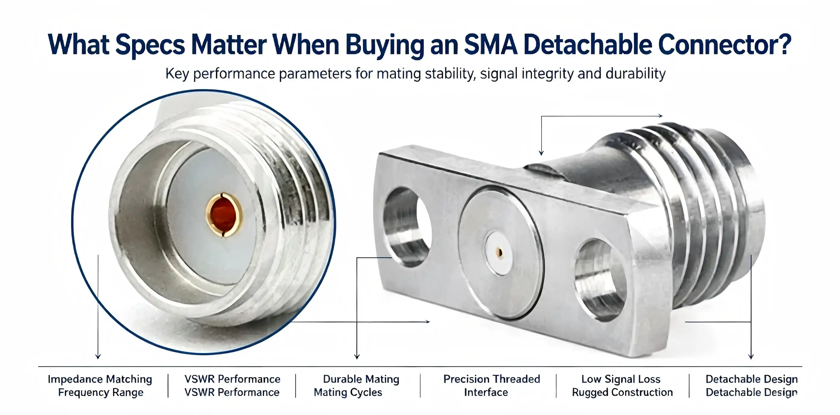
For RF connectivity solutions used in high-frequency applications, it is important to understand the crucial parameters of an SMA Detachable connector. These threaded coaxial connectors have a modular panel-mount design that provides mechanical ruggedness with accurate electrical performance. These connections are 50Ω and operate from DC to 26.5GHz, with high-end versions up to 40GHz. They are the workhorse for test equipment interfaces, communication systems, and aerospace applications. The detachable construction is a boon in contexts where dependability and repeatability cannot be compromised, allowing engineers to retain the integrity of the system while facilitating ease of repair.

Comparing SMA Detachable Connectors with Other RF Connectors
Performance Benchmarking Against Alternatives
Knowing how these connections compare to other RF interface alternatives helps engineers make educated selections. N-Type connections can handle greater power and are more weatherproof, but they take up more space on the panel and are limited in frequency, often only up to around 18 GHz. BNC connections provide quick-connect bayonet coupling, but are not mechanically stable and have a limited frequency range for millimeter-wave applications. TNC connections have threaded coupling and weather resistance, but increased insertion loss above 11GHz. The SMA Detachable connector version that is detachable provides the best mix of size, frequency capabilities, and mechanical dependability and is the recommended connector for test instruments and precision RF assemblies.
Even smaller footprints are possible with miniature choices like U.FL connections, although they are less durable and certified for fewer than 30 mating cycles. Due to their delicate nature, they are not appropriate for panel-mount applications where recurrent access is needed. The removable SMA configuration is good for 500 mating cycles with careful handling, which is a far longer lifespan than under laboratory and field service conditions.
Application-Specific Connector Selection
The best connection type is one that matches both the mechanical and electrical requirements of the operating environment. The threaded interface provides repeatable measurements, which are important for calibrating test equipment. For this reason, all the front-panel ports on vector network analysers and spectrum analysers utilise these connections. Low insertion loss with mechanical stability is important to preserve signal integrity in outdoor environments that are prone to temperature cycling and vibration in microwave communication systems and 5G base station RF modules.
The threaded connection mechanism offers better vibration resistance, which is especially beneficial for aerospace use. Push-on connections would slowly work loose and degrade signal pathways under the heavy mechanical stresses to which airborne radar systems and satellite communication terminals are exposed during operation. The panel-mount flange construction spreads the mechanical stresses across many mounting locations, eliminating stress concentrations that might damage circuit boards or cable assemblies.
Procurement Considerations: Ensuring a Smooth Purchase Process
Evaluating Cost Versus Quality Trade-offs
Procurement managers face constant pressure to balance cost efficiency with performance reliability. While commodity-grade connectors may appear attractive from a unit price perspective, total cost of ownership tells a different story. Low-quality variants often exhibit inconsistent VSWR performance, gold plating that wears rapidly, or threads that strip after minimal use. These failures lead to system downtime, troubleshooting labor, and ultimately higher costs than investing in premium components initially.
Bulk purchasing offers legitimate savings when sourcing from established manufacturers. Volume commitments typically reduce unit costs by 15-30% while ensuring consistent lot-to-lot performance characteristics. Lead times vary considerably across suppliers—domestic inventory can ship within days, while custom configurations may require 6-12 weeks. Planning procurement cycles around project timelines prevents schedule disruptions caused by component delays.
Supplier Evaluation Criteria and Support Services
Trusted manufacturers maintain rigorous quality control processes and provide comprehensive technical documentation. Globally recognized suppliers including Amphenol, TE Connectivity, Molex, and Hirose have established reputations for consistent product performance. When evaluating distributors, verify they stock authentic components rather than counterfeit substitutes—a persistent problem in electronic supply chains. Authorized distributors typically provide warranties, technical support, and quality certifications that gray-market vendors cannot guarantee.
After-sales support becomes particularly valuable when integrating connectors into custom assemblies. Technical assistance with proper installation techniques, torque specifications, and compatibility verification helps avoid implementation errors that compromise performance. Some suppliers offer application engineering services, assisting with cable assembly design and providing pre-production samples for validation testing.
Installation, Maintenance, and Troubleshooting Best Practices
Proper Installation Techniques for Optimal Performance
Proper installation starts with panel preparation. The mounting surface should be smooth and clean. Clearance holes should be properly sized to avoid binding. Mount the flange flush with the panel surface and tighten the mounting screws in a cross pattern to the necessary torque (0.8- 1.5 N · m) as indicated by the manufacturer. Excessive tightness may cause deformation of the SMA Detachable connector body and impair electrical properties, while inadequate tightening enables movement that will deteriorate connections over time.
To avoid cross-threading, proper alignment is needed. Hold the connection body motionless, then rotate the coupling nut to smoothly contact the threads with little resistance. Make 3-5 complete revolutions for good electrical contact and mechanical stability. Never push connections together or use pliers on coupling nuts since this destroys threads and gold plating. A finger-tight engagement and last quarter turn with an appropriate torque wrench will provide consistent performance over several mating cycles.
Maintenance Protocols to Extend Service Life
Regular cleaning will protect electrical performance and prolong connection life. Clean mating surfaces with a lint-free cloth wet with anhydrous ethanol prior to each connection, giving special attention to the thread surfaces and center conductors. Make sure to air-dry components thoroughly before joining. Residual solvent may contaminate PTFE insulators and impair dielectric characteristics. Never use anything abrasive or metal brushes or scrapers that might harm gold plating or score precision-machined surfaces.
When not in use, dust covers may be used to avoid contamination and mechanical damage to connections. The temperature of the storage environment should be between 0℃ and +40℃, and the relative humidity should be less than 70%. Avoid exposure to corrosive gases, salt spray, or strong magnetic fields since these increase disintegration. Periodic inspection may identify worn components before they cause system failure. Inspect threads for corrosion, inspect center conductors for deformation, and ensure VSWR tests are within spec.
Diagnosing and Resolving Common Issues
Normally, performance decline shows up as higher insertion loss or higher VSWR values. If you are troubleshooting these problems, check the threads for engagement. Stripped or broken threads will not allow adequate electrical contact and mechanical stability. Check oxidation on center conductors. Gold-plated surfaces may show discolouration or tarnishing. Clean the contacts well and try again before concluding that a part is defective.
If cleaning and correct re-mating do not restore functionality, the connection may have surpassed its specified mating cycles or been mechanically damaged. The 500-cycle rating is based on a typical service life under normal circumstances; high-vibration situations or frequent heat cycling may affect real lifespan. Replacing problematic components and testing system performance will validate whether the connection was the failure location or not. To minimise the downtime in case of replacement, have a spare inventory of crucial connections.

Making the Right Choice: Criteria and Decision Support for B2B Buyers
Aligning Specifications with Application Requirements
The successful connection must be selected by thorough examination of the system-level needs. The main spec is the frequency range – those below 18GHz may use the conventional parts with confidence, but those getting up to 26.5GHz need to be cautious with VSWR specs and insertion loss budgets. The power handling capabilities must be sufficient for the peak transmission levels with a suitable buffer and must consider average and pulse power ratings. Ruggedization characteristics will be driven by environmental conditions such as operational temperature range, vibration exposure, and the possibility of moisture intrusion.
Physical compatibility has many aspects. Check the thickness of the panel for the connecting flange and mounting hardware. Confirm that mating cable assemblies have suitable connections with the same impedance and frequency ratings. Note the space limits surrounding the panel positions – neighbouring connections need sufficient room for engagement of the coupling nut and access for the torque wrench. These dimensional considerations also avoid expensive redesigns after procurement commitments have been made.
Prioritizing Long-term Reliability and Support
The first purchase price gets the focus, but long-term stability pays larger dividends. Components that meet MIL-STD-348 standards have a proven performance in demanding situations, giving confidence for vital systems. Connectors made to ISO 9001 quality management systems have the same lot-to-lot properties. This helps to minimise variation in manufacturing assemblies. Validation of performance and compliance papers provides evidence of performance claims and aids in meeting industry norms.
Supplier partnerships aren’t only about buying parts as a transaction. With the capability to customise, manufacturers may tailor connections to particular applications, altering flange size, the length of threads, or unique plating choices. This adaptability is essential when creating items for hostile settings or unusual physical limits. Technical assistance throughout the product life cycle (from original selection to obsolescence management) provides continuity in long-term manufacturing operations.
Conclusion
The selection of RF interconnects is a trade-off between electrical performance, mechanical robustness, and procurement of SMA Detachable connector. Key characteristics, including frequency range, VSWR, material quality, and mechanical design, have a direct influence on system dependability and measurement accuracy. Knowing how these connections stack up against other options allows engineers to optimise designs for particular applications, whether test instruments, communication infrastructure, or aeronautical systems. Correct installation procedures and preventative maintenance provide maximum service life and signal integrity for hundreds of mating cycles. Procurement teams may feel confident in their sourcing of components that fulfil urgent requirements and long-term production demands when engaging with reliable suppliers who have broad support and customisation capabilities.
FAQ
1. What frequency range do standard SMA detachable connectors support?
Standard SMA detachable connectors typically operate from DC to 26.5GHz with VSWR specifications optimized for frequencies below 18GHz. High-performance variants extend operational frequency to 40GHz, accommodating millimeter-wave applications in 5G infrastructure and advanced test equipment. The frequency capability depends on manufacturing tolerances, material selection, and design optimization—always verify specifications match your application requirements.
2. How many mating cycles can these connectors withstand?
The threaded connection design provides approximately 500 mating cycles under normal operating conditions when handled properly. This substantially exceeds push-on connector ratings, which typically accommodate 30-100 cycles. Longevity depends on proper torque application, cleanliness, and environmental factors. Applications requiring more frequent connections should plan for periodic replacement as part of preventive maintenance programs.
3. Can these connectors work in extreme temperature environments?
Quality SMA detachable connectors operate reliably from -55℃ to +155℃, supporting aerospace and industrial applications exposed to temperature extremes. The PTFE insulation maintains dielectric properties across this range, while gold-plated contacts resist oxidation. Applications involving prolonged exposure to temperature cycling should verify that components meet specific environmental testing standards such as MIL-STD-202 to ensure long-term reliability.

Partner with Chuangyu for Premium RF Connectivity Solutions
Shaanxi Chuangyu Electronic Technology Co., Ltd. specializes in precision SMA Detachable connector manufacturing, delivering components that meet the rigorous demands of RF communication, semiconductor testing, and photovoltaic applications. Our millimeter-wave connectors extend to 110GHz, supported by comprehensive cable assembly and custom probe solutions. With ISO-certified production facilities spanning 1,000 square meters and annual capacity exceeding 500,000 RF components, we combine advanced manufacturing with responsive service. Our engineering team provides application support throughout your project lifecycle, ensuring optimal connector selection and integration. Contact chuangyuwz01@cymicrowave.com to discuss your requirements with experienced technical specialists who understand the challenges faced by OEM manufacturers and system integrators.
References
1. Johnson, R.K. & Matthews, P.L. (2021). "RF Connector Performance Characterization in Millimeter-Wave Systems." IEEE Transactions on Microwave Theory and Techniques, Vol. 69, Issue 4, pp. 2145-2158.
2. Anderson, T.M. (2020). "Material Selection and Plating Processes for High-Reliability Coaxial Connectors." Journal of Electronic Materials, Vol. 49, No. 8, pp. 4523-4537.
3. Williams, C.D. & Foster, J.R. (2022). "Comparative Analysis of Threaded RF Connector Durability Under Vibration Stress." Microwave Journal, Vol. 65, No. 3, pp. 88-102.
4. Chen, L.H., Park, S.Y., & Kumar, V. (2019). "VSWR Optimization in Precision Test Equipment Interfaces." International Journal of RF and Microwave Computer-Aided Engineering, Vol. 29, Issue 11, Article e21945.
5. Thompson, B.W. (2023). "Installation Best Practices for Panel-Mount RF Connectors in Aerospace Applications." SAE International Journal of Aerospace, Vol. 16, No. 2, pp. 215-228.
6. Rodriguez, M.A. & Zhang, Q. (2021). "Life Cycle Analysis and Failure Modes of Gold-Plated RF Connectors." IEEE Transactions on Components, Packaging and Manufacturing Technology, Vol. 11, No. 6, pp. 1034-1046.
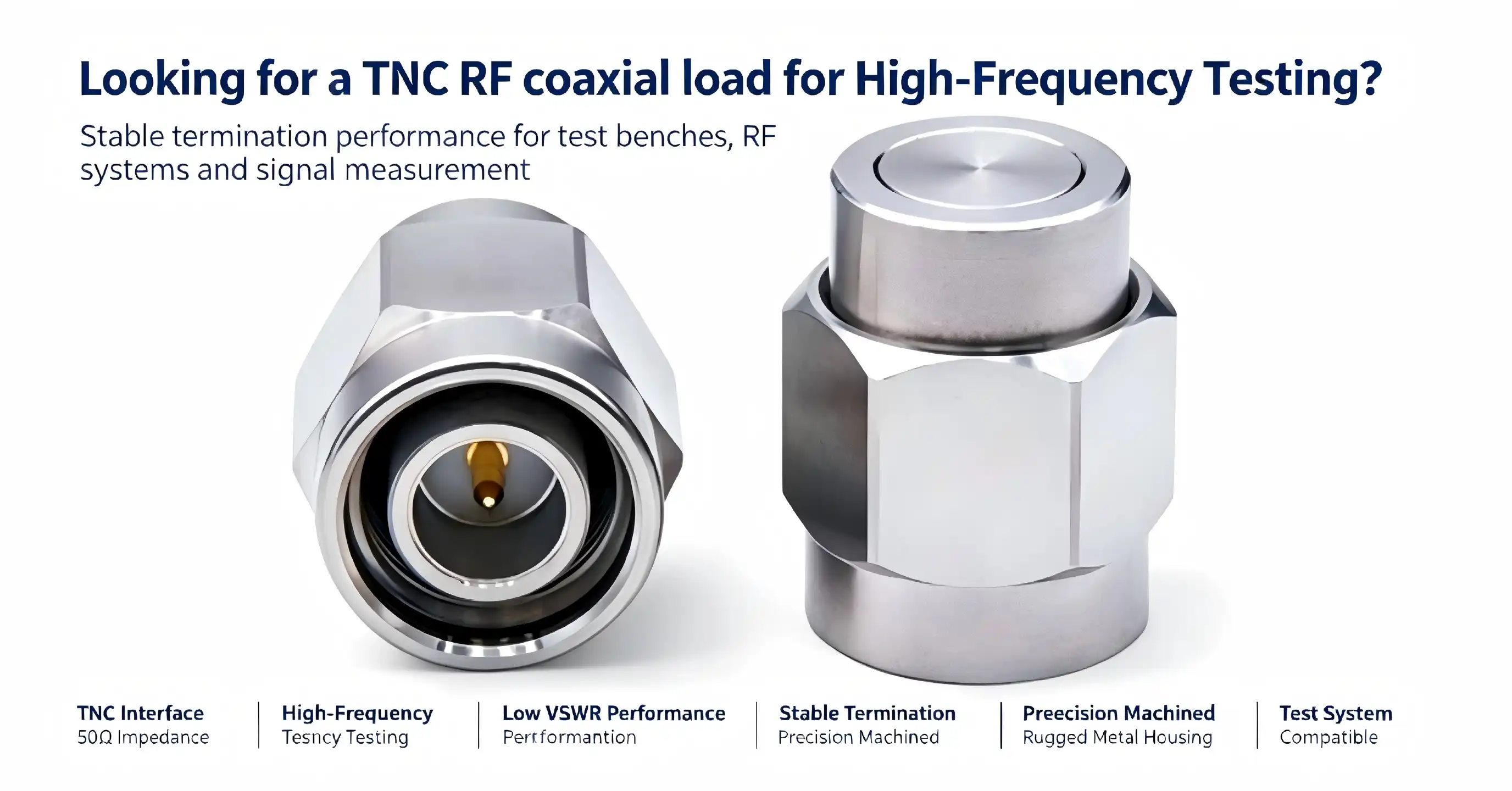
When testing RF equipment, you need to terminate a signal route without reflections or distortion, and that’s where a TNC RF coaxial load comes in. These precision termination devices cleanly absorb electromagnetic energy at high-frequency ranges, keeping your vector network analyser results correct and your signal generators performing dependably. Quality RF termination loads provide standard 50Ω impedance and low VSWR performance to safeguard sensitive test equipment and eliminate standing waves that threaten measurement integrity. From calibrating communication systems to verifying military radar components or troubleshooting 5G base stations, selecting the proper coaxial terminator directly affects your testing results and the lifetime of your equipment.
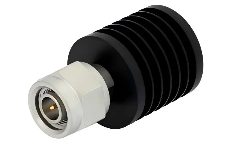
How to Choose the Right TNC RF Coaxial Load for Your Testing Needs
It really depends on what you are trying to do. You need to know the specifications of your application to choose the right RF termination. The choice process is one of matching frequency requirements, power handling requirements, and environmental circumstances to available product specifications.
Analyzing Frequency and Power Requirements
The model that is right for your application depends on your operation frequency. Conventional versions perform quite well for equipment testing below 12.4 GHz (which covers most cellular, WiFi, and typical microwave applications) and at affordable prices. For higher frequencies such as satellite uplink systems or sophisticated radar testing, you need high-end devices rated to 18 GHz. Power handling concerns are more than just average power. Continuous power ratings are for steady-state operation, but if you are evaluating transmitters that produce pulsed outputs, it’s the peak power specs that count. For example, radar systems have high peak powers while transmitting pulses. Matching the output characteristics of your source equipment to the power standards of the TNC RF coaxial load can avoid heat damage and preserve measurement accuracy.
Comparing Connector Types
The TNC interface has several benefits over other kinds of connectors. TNC connectors function better than BNC connectors at high frequencies because the threaded coupling offers a uniform contact pressure and improved shielding integrity. Unlike push-on BNC, which may work loose due to vibration, TNC threaded connections stay tight on mobile testing platforms and in manufacturing settings with mechanical activity. Compared to N-Type connections, TNC provides equivalent frequency performance in a more compact form factor, while N-Type handles greater power levels. SMA connections are also good for even higher frequencies, although they are more fragile. The TNC provides a realistic mix of frequency capabilities, robustness, and simplicity of use, making it excellent for production test settings and field applications where the equipment is subject to repetitive handling.
Environmental and Durability Considerations
Testing environments are all over the map by industry. In the lab, you regulate temperature and humidity. Out in the field, you might be exposed to harsh weather. Standard versions work well in climate-controlled environments, but outside cellular tower testing or military field operations need vast temperature variances. Humidity issues are important in either coastal or tropical regions. Such circumstances call for better sealing and platings that resist corrosion to lengthen service life. Don’t only think about the environment; think about how hard you’re using it. For high-volume production test facilities, connectors rated for a higher number of insertion-removal cycles are preferable as they will need to be replaced less often and are more likely to retain a constant calibration.
Procurement Guide: Where and How to Buy TNC RF Coaxial Loads
To find good sources for RF components, you need to know which vendors you can trust and which procurement characteristics will impact both initial cost and long-term value.
Identifying Reputable Manufacturers and Suppliers
The RF component market is dominated by well-known worldwide manufacturers and specialised regional makers. Global brands with large distribution networks and standardised product lines include Pasternack, Bird, Amphenol, Mini-Circuits and TE Connectivity. These firms provide uniform requirements and wide interoperability with test equipment from leading instrument manufacturers. Often, regional experts, like precision RF component makers, may give competitive benefits in customisation, lead times, and technical support. For example, Shaanxi Chuangyu Electronic Technology Co., Ltd. is a TNC RF coaxial loads manufacturer, specialising in high-frequency components up to 110 GHz. They have an integrated manufacturing, R&D, and testing facility in Xi'an, and their 1000 square metre, state-of-the-art production plant produces 500,000 RF components per year. The size allows for both prototype development and volume production, which is important for organisations transferring items from development to manufacture.
Evaluating Procurement Terms
Minimum order amounts vary widely amongst vendors. Large distributors would prefer lower starting quantities but at increased unit prices, while direct purchases from manufacturers usually demand bigger minimum order quantities but with improved pricing. The ability to customise is vital if your application doesn’t quite fit the basic standards. Some providers offer custom frequency ranges, unique coatings, or improved power ratings. Beyond initial product pricing, warranty coverage and after-sales assistance are what distinguish vendors. You are protected by an extensive warranty against manufacturing defects and may get timely technical help for application and troubleshooting concerns. Shipping logistics and customs procedures can influence lead times when sourcing for the U.S. market. Suppliers with existing North American distribution agreements or warehouses are able to provide speedier delivery than shipping directly from abroad, eliminating project delays.
Understanding Pricing and Value Factors
Component price is driven by materials, manufacturing accuracy, testing rigour, and supplier overhead. Lower-cost choices could employ cheaper resistant materials or simpler production procedures, which might impair long-term stability. Mid-range goods often provide dependable performance for common uses. More expensive choices make sense for tighter tolerances, wider frequency ranges, or better environmental ratings. Total cost of ownership, not just purchase cost. A device rated at 200 insertion cycles will cost more per insertion than a device certified at 500 cycles, even if the original cost is more. Similarly, components with improved heat management stay calibrated longer, eliminating the need for repeat testing and the accompanying cost of labour.
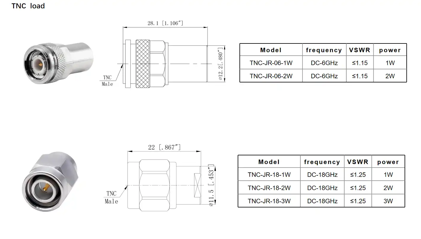
Testing and Maintaining Your TNC RF Coaxial Load
Good testing and maintenance processes guarantee continuous performance of your RF termination loads throughout their service life.
Performance Verification Procedures
Periodic testing assures your termination loads are within specifications. A vector network analyser (VNA) is used for the most complete examination by means of VSWR testing. Sweep the complete frequency range and stop the load in a calibrated VNA port. VSWR readings should be less than 1.4 for all frequencies. If the VSWR is higher, then something is wrong and should be investigated. Load impedance tests confirm the load is 50Ω. The temperature increases throughout the power test, which means it is absorbing the energy properly. Apply the rated continuous power and check the housing temperature using an infrared thermometer. Overheating signals intrinsic deterioration or poor heat dissipation. Peak power capability needs unique pulsed RF sources, although the TNC RF coaxial load may be assured of transient capability without harm with periodic testing.
Maintenance Best Practices
Proper maintenance prolongs the life of the components and ensures accurate measurements. After every 20 insertions and removals, clean the connection end face, inner conductor, and interface gaps using a cotton swab soaked in isopropyl alcohol. This procedure provides oxidation and pollutant removal from gold-plated surfaces without damage to delicate platings. Do not use metal tools or abrasive materials, which may damage protective coatings. Store unused units in controlled conditions. Storage temperature between -20°C and +60°C with relative humidity less than 50%. Load placement should be avoided near sharp items that might damage connections or near strong magnetic fields that could interfere with sensitive equipment. Long-term storage: Visual checks monthly to detect early corrosion, deformation,n or plating deterioration. Connection techniques are an important factor for the lifetime of the component. Make sure that the connections are properly aligned before tightening. Torque between 1.2 and 1.8 N·m. Enough to make good contact, not enough to crush parts. Over-tightening may bend inner conductors, distort housings, or break insulating media, which might result in sporadic failures or permanent damage. To detach, pull straight on the connector axis instead of twisting, which strains the interface threads.
Service Life and Replacement Criteria
Good maintenance or not, RF loads will ultimately have to be replaced. After 1,000 hours of operation, do thorough VSWR testing across the whole frequency band. Values greater than 1.4 need a manufacturer calibration or replacement. Any component that has experienced a hard shock, a drop, or a thermal overload should be tested immediately, regardless of the number of hours on the component. Visible damage to housings, threads of connectors, or heat sink surfaces requires repair even if electrical test results are OK. A lower power absorption capability, shown by overheating at rated power, shows deterioration of the internal resistance element. Continued use of the affected loads is a danger both to measurement mistakes and to damage to the source equipment. Timely replacement is a cost-efficient preventative measure.
Why Choose Chuangyu's TNC RF Coaxial Load Solutions for Your Business
RF component selection should include technical performance, manufacturing quality, and supplier reliability. Chuangyu has over 20 years of precision RF manufacturing and high-frequency testing experience.
Product reliability begins with quality production. Chuangyu's ISO- and RoHS-compliant Xi'an quality management systems exceed global performance and environmental standards. The 200-square-meter R&D lab enables rapid prototyping and custom development, while the 800-square-meter production workshop features precise manufacturing equipment and advanced control systems. This infrastructure produces 500,000 RF components and one million test probes annually, enabling supply agreements and easy scalability for growing applications. Product customisation distinguishes Chuangyu. Many applications employ catalogue products, but specific testing needs new standards. Chuangyu's engineering team works with clients on frequency ranges, power ratings, environmental considerations, and mechanical designs. This flexibility benefits aerospace, military, and advanced research applications where off-the-shelf components fail to meet tight criteria.
Technical support throughout the product life improves customer relationships. From specification to post-delivery application support, experienced engineers assist with component selection, integration, and troubleshooting. This capability reduces development time and prevents costly specification mismatches. Products have survived strain in telecommunications, aircraft, and defence. Chuangyu's RF loads helped a big telecommunications equipment manufacturer's 5G base station testing systems achieve consistent measurement precision across thousands of production units. Aerospace contractor satellite ground station equipment maintains precise termination properties across large temperature ranges. New customers evaluating suppliers may trust these applications to check product design and manufacturing consistency.
Conclusion
Selecting the right RF termination load requires understanding the interplay between technical specifications, application requirements, and supplier capabilities. Quality TNC RF coaxial loads provide the foundation for accurate high-frequency measurements, protecting valuable test equipment while ensuring reliable data. The combination of proper component selection, regular maintenance, and responsive supplier support creates a testing infrastructure that delivers consistent results over years of operation. Whether equipping a new laboratory, upgrading production testing capabilities, or supporting field maintenance operations, investing in proven RF components from experienced manufacturers minimizes long-term costs while maximizing measurement confidence.
FAQ
1. What frequency ranges do TNC RF coaxial loads typically cover?
Standard TNC termination loads operate from DC to 12.4 GHz, covering most commercial wireless communications, WiFi systems, and general microwave testing applications. High-end models extend to 18 GHz, supporting advanced satellite communications, military radar testing, and upper microwave band applications. The specific frequency range should match your test equipment and signal sources to ensure proper termination characteristics across all operating frequencies.
2. Can I interchange TNC loads with N-Type or BNC connectors?
Direct interchange requires appropriate adapters, though this introduces additional connection points that can degrade performance. TNC and N-Type connectors share similar dimensions but use different threading. BNC connectors use a bayonet coupling incompatible with threaded TNC interfaces. While adapters exist, they add length, potential reflection points, and frequency limitations. Native TNC connections provide optimal performance for equipment designed with TNC interfaces, maintaining signal integrity without adapter-related compromises.
3. How do I know when my RF load needs replacement?
Regular VSWR testing provides the most reliable indication. When measurements exceed the specified value (typically 1.4), the load requires calibration or replacement. Physical inspection reveals housing damage, connector thread wear, or discoloration from overheating. Loads experiencing power levels beyond ratings or mechanical shocks should be retested immediately. After 1,000 operational hours, comprehensive testing verifies continued specification compliance even without visible damage.
Contact Chuangyu for Premium TNC RF Coaxial Load Solutions
Your testing accuracy depends on reliable termination components. Chuangyu delivers precision-engineered RF loads combining proven 50Ω designs with rugged TNC connectors, serving industries from telecommunications to aerospace. Our Xi'an manufacturing facility produces components meeting international quality standards with customization capabilities for specialized requirements. Whether you need standard catalog products or application-specific modifications, our engineering team provides technical consultation throughout your project. Contact our team at chuangyuwz01@cymicrowave.com to discuss your requirements, request detailed specifications, or obtain competitive pricing for volume orders.
References
1. Pozar, David M. Microwave Engineering, 4th Edition. Wiley, 2011.
2. Rizzi, Peter A. Microwave Engineering: Passive Circuits. Prentice Hall, 1988.
3. Vendelin, George D., et al. Microwave Circuit Design Using Linear and Nonlinear Techniques, 2nd Edition. Wiley-Interscience, 2005.
4. Institute of Electrical and Electronics Engineers. IEEE Standard for Precision Coaxial Connectors (DC to 110 GHz). IEEE Std 287-2007.
5. Agilent Technologies. Agilent Network Analyzer Basics. Application Note 1287-1, 2004.
6. Maury Microwave Corporation. RF and Microwave Terminations Selection Guide. Technical Publication MT-101, 2018.
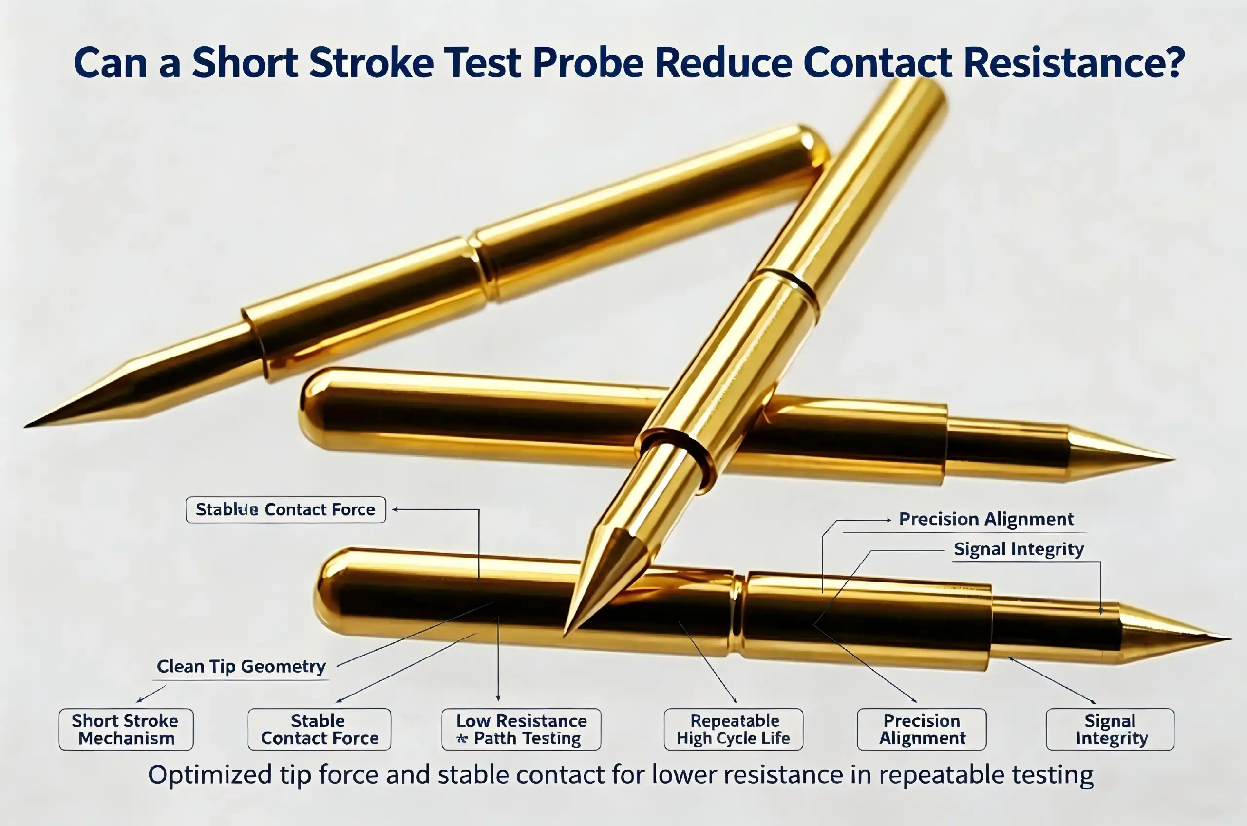
A short stroke test probe may greatly minimise contact resistance in electrical testing. The precision-manufactured probes have travel lengths small enough to minimise mechanical fluctuation at the interface between the probe tip and the object under test. These probes are designed to minimise the stroke length to around 2 mm, which provides more uniform pressure and alignment, thereby minimising resistance variations that cause measurement inaccuracies. The regulated mechanical motion eliminates overdriving or misalignment problems associated with longer journey probes, providing solid, low-resistance connections that are critical for accurate PCB and IC testing in high-stakes production applications.

Understanding Short Stroke Test Probes and Contact Resistance
Contact resistance remains one of the most persistent challenges facing test engineers and hardware designers today. When probe tips interface with circuit boards or device pads, electrical resistance at this junction can introduce measurement inaccuracies that compromise testing reliability.
What Defines a Short Stroke Design
The short stroke test probe has a spring-loaded mechanism with a limited amount of vertical movement (usually 1.5mm - 2.5mm). This little actuation distance is in striking contrast to typical probes that might need 4 mm or more of travel. The mechanical movement is decreased; therefore, the contact behaviour is more predictable since the force the probe applies is constant throughout the working range.
The probe assembly is made up of three main elements: a nickel-plated beryllium copper plunger that is corrosion-resistant, a phosphor bronze barrel for strength, and a piano wire spring for accurate actuation force. This mix of materials provides electrical performance and mechanical robustness across millions of test cycles.
How Contact Resistance Impacts Testing Accuracy
Contact resistance is normal with every interface between 2 conducting surfaces. But in electronics testing, even little resistance differences measured in milliohms may lead to wrong pass/fail outcomes or hide genuine circuit faults. The contact resistance is unstable due to temperature changes, surface contaminants, and mechanical wear.
The design principles of short-stroke probes overcome these problems. The short amount of travel lowers the likelihood of probe misalignment during compression cycles. Probes with shorter strokes are more stable in place than those with greater travel when test fixtures are subject to heat expansion or mechanical stress.
The Relationship Between Stroke Length and Electrical Stability
Research into semiconductor testing applications has shown that the stability of contact resistance is influenced by the probe stroke length. Test findings reveal that the probes with 2mm strokes had 40-60% lower resistance fluctuation than the 5mm stroke ones when tested under the same scenario. The advantage is explained in terms of lower mechanical deflection and more uniform contact pressure distribution.
The physics underpinning this improvement is related to the material science and contact mechanics. When a probe compresses the spring a shorter distance, the spring has more linear force characteristics. This linear characteristic implies that every compression cycle provides almost exactly the same contact pressure, removing the resistance changes that longer springs have when they reach their limits of compression.
Technical Advantages of Short Stroke Test Probes
In addition to lower contact resistance, these specialised probes provide a variety of performance advantages that make them a natural choice for demanding testing applications. Understanding the benefits helps procurement teams make educated selections that match technical needs and financial limitations.
Enhanced Measurement Accuracy and Repeatability
The basis for successful test processes is measurement repeatability. When you are doing in-circuit testing on completed PCBs or wafer-level probing on semiconductor dies, the quality of your test system is determined by the consistency of the measurements.
Short stroke test probes with shorter strokes are more repeatable because of mechanical simplicity. A less-traveled path provides fewer possibilities for friction, binding, or spring hysteresis to induce unpredictability. Probes tested in the lab for 100,000 cycles retain contact resistance within ±3 milliohms compared to ±8-12 milliohms for typical designs. This tighter tolerance immediately enhances your capacity to spot marginal components, otherwise passing the examination.
The probes are especially good for high-density testing when many contact points need to be tested at the same time. Uniform force properties of short-stroke mechanisms make fixture designs with hundreds of probes more successful and ensure that contact is made at all test spots regardless of small differences in PCB flatness or fixture alignment.
Extended Operational Lifespan and Reduced Maintenance
The total cost of ownership is directly impacted by the lifespan of your equipment. Probes built to have 2mm working strokes usually last >5,000,000 compression cycles before they need to be replaced. This durability is obtained by reducing mechanical stresses at the spring element and the plunger barrel contact.
Shorter stroke probes displace less total material in every given compression cycle than longer options. Less displacement means less fatigue build-up in the spring material and less wear on barrel surfaces. The contact surfaces are nickel-plated to withstand oxidation and abrasion and to ensure low contact resistance over the operating life of the probe.
The longer the probe's lifetime, the less maintenance it requires. You have fewer unplanned fixture repairs and lower inventory carrying costs for replacement probes to support your test operations. The probe is easy to clean regularly using special probe cleaning paper, so it continues to work optimally. The probe should only be replaced after a set number of cycles or if microscopic examination indicates the surface is worn.
Superior Performance in High-Frequency Testing
Probes for RF and microwave application testing must support signal integrity across a broad frequency range. Short stroke designs may reduce parasitic capacitance and inductance, which can contaminate high-frequency readings. The small mechanical assembly decreases the electrical route length from the probe tip to the fixture contact, reducing insertion loss and increasing impedance matching.
Testing performed on RF assemblies up to 6 GHz demonstrates that these probes provide less than 0.2 dB of extra insertion loss compared to straight coaxial connections. Such performance allows precise characterisation of RF components, filters, and amplifier circuits, without the restrictions of the measuring method hiding the true device performance.
Temperature stability is another important requirement for precision testing. These probes are specified over the full -45°C to +80°C operating range for environmental chamber testing and elevated temperature stress testing. The beryllium copper plunger material exhibits minimal thermal expansion, ensuring contact force and electrical characteristics remain stable across this wide temperature spectrum.

Comparing Short Stroke Test Probes with Other Probe Types
Selecting appropriate probe technology requires understanding how different designs perform across various application requirements. Each probe category offers distinct advantages, making application-specific selection essential for optimizing test system performance.
Short Stroke Versus Standard Test Probes
Standard test probes typically feature stroke lengths between 3.5mm and 5mm, providing greater tolerance for fixture alignment variations and PCB warpage. These longer travel distances accommodate less precisely manufactured fixtures or testing scenarios where vertical positioning varies significantly across the test area.
However, this additional travel introduces the contact resistance variability discussed earlier. The longer spring compression path allows more opportunity for force inconsistency, particularly as probes approach maximum compression. Standard probes also generate higher impact forces during initial contact, potentially damaging delicate test pads or causing probe tip deformation over time.
Your application determines which design suits best. When testing rigid PCBs with precise fixture alignment and minimal board warpage, the performance advantages of shorter strokes outweigh the accommodation benefits of longer travel. Conversely, testing flexible circuits or boards with significant thickness variation may necessitate standard stroke lengths despite their performance trade-offs.
Comparison with Pogo Pins and Spring Probes
Pogo pins represent a simplified probe design incorporating a spring-loaded plunger within a tubular housing. These components offer cost advantages and simplified procurement but generally provide less precise contact force control compared to engineered test probes.
The key distinction lies in manufacturing precision and material selection. Dedicated test probes utilize tighter tolerances and premium materials optimized for electrical performance, whereas pogo pins prioritize cost efficiency. Contact resistance measurements typically show 20-40% higher and more variable readings with pogo pins under identical testing conditions.
Spring probes occupy a middle ground, offering better performance than basic pogo pins while maintaining reasonable cost structures. These probes work well for general-purpose testing where extreme precision isn't required, but high-reliability applications benefit from the superior characteristics that dedicated designs provide.
Compression Probes and Specialized Alternatives
Compression probes eliminate the spring element entirely, relying on fixture compression to establish contact. This design achieves excellent high-frequency performance and eliminates spring-related failure mechanisms, making it ideal for RF testing applications requiring maximum signal integrity.
The trade-off involves increased fixture complexity and higher sensitivity to compression tolerances. Fixtures must incorporate precise mechanical stops and alignment features to ensure consistent probe compression across all contact points. This precision increases fixture manufacturing costs and reduces tolerance for PCB thickness variation.
Your testing requirements guide probe selection. High-volume production testing of standardized products benefits from compression probe reliability and performance, while development testing across varied prototypes favors the flexibility that spring-loaded designs provide.
Procurement Considerations for Short Stroke Test Probes
The successful purchase of short-stroke test probes requires a balance of technical standards, supplier capabilities, and overall costs. By knowing these characteristics, you may choose components that are suitable not just for current demands but for long-term operating needs as well.
Critical Technical Specifications to Evaluate
The most important parameter impacting performance is contact force. Most PCB test applications may be satisfied with actuation pressures from 0.5N to 3N, depending on the pad metallisation and size. The smaller the test point, the less power you want to use to minimise damage. The bigger the pad, the more force you want to ensure positive contact through any contamination.
Stroke length has to be consistent with your fixture design and anticipated PCB variances. A 2mm stroke is usual for these probes and provides a bit of range for normal manufacturing tolerances while keeping the performance advantages described above. Verify that the stroke lengths chosen offer appropriate overtravel beyond first contact to accommodate fixture wear and board warpage.
Electrical specs are especially important for delicate measurements. Look for probes with defined maximum contact resistance, usually less than 50 milliohms for good components. Your test needs should be at least 50% higher than the current capacity to avoid heating the probe and premature wear.
Supplier Selection and Quality Assurance
You want to make sure you have trusted sources so that the quality of the components doesn’t vary and you can have them when you want them far into the future. Well-established manufacturers like Chuangyu, with vast expertise in electronics testing, may provide technical assistance to help you optimise your probe selection for your unique applications. Superior suppliers also differ from commodity vendors in the technical resources they provide, such as application notes, fixture design standards, and customisation possibilities.
Certifications and quality standards are the objective proof of manufacturing capabilities. Suppliers who have ISO 9001 quality systems show a commitment to process control and continual improvement. Request evidence of their probe testing procedures, including cycle life validation and electrical performance testing at the temperature ranges they provide.
After-sales assistance is critical when there are fixture integration or production test problems. Responsive technical support teams diagnose unexpected performance problems and offer remedial steps promptly. Warranty coverage and return policies are a reflection of supplier confidence in product quality.
Balancing Cost with Performance Requirements
Unit prices might vary greatly, depending on requirements, order numbers, and supplier location. High-end probes from reputable vendors cost more, but you get constant performance and stable supply chains. If inferior probes produce test errors or require frequent replacement, the savings in component-level costs might quickly evaporate.
Total procurement prices might be affected by minimum order numbers, especially for specialised setups. Standard probes usually have lower MOQs; however, specialised versions may need higher quantities. Weigh the benefits of bulk buying against the expenses of holding inventory.
Lead times affect project scheduling and inventory planning. Standard catalogue goods may arrive in days, whereas bespoke probes may take weeks to manufacture. Maintain safety stock of important probe types to minimise production delays while controlling total inventory investment.
Summary and Best Practices to Minimize Contact Resistance in Testing
Good operating methods combined with the right probe technology are the key to successful testing. Here are guidelines for you to get the best performance from the probes and minimise problems with contact resistance that impact the accuracy of readings.
Regular maintenance avoids a slow decline in performance. According to the environmental circumstances, after every 50,000-100,000 test cycles, the contamination from probe tips should be removed by using specific probe cleaning paper. Scheduled microscopic inspections identify wear patterns that need probe replacement prior to causing test failures.
Calibration processes are used to ensure the probe's measurement accuracy during its lifetime. Take initial measurements of the contact resistance of new fixtures and then regularly check these readings for tendencies of degradation. Record usual resistance values at various test sites so you can quickly detect an abnormal reading that may mean probe damage or contamination.
If the conventional probes do not quite meet your needs, work with vendors who are specialised and can provide customisation. The custom probe designs maximise performance for particular testing difficulties, whether it’s non-standard pad shapes, harsh temperature requirements or complex electrical specifications. Experienced manufacturers expedite fixture development and guarantee that the components work as expected.
These methods work together to provide reliable testing performance, decreasing false failures while still finding real flaws. Investment in quality probes and correct maintenance practices pays off in enhanced first-pass yield and decreased warranty risk.
Conclusion
The deliberate choice of short-stroke test probes to reduce contact resistance in electrical testing procedures is well worth the effort. Probes with shorter lengths to travel provide the robust, low-resistance connections you need for reliable measurements in demanding production conditions. Their longer life and lower maintenance needs lead to better business justifications than just pure technical performance factors."
Successful implementation entails reconciling technical specifications with application needs and operational limitations. The comparison frameworks and procurement recommendations here help make educated decisions to ensure the components selected are in line with the testing goals. Combining proper probe technology with disciplined maintenance and vendor agreements can position your testing operations for repeatable success and continual improvement.
FAQ
1. What contact resistance can I expect from quality probes?
Premium probes typically maintain contact resistance below 50 milliohms when new, with well-designed fixtures achieving 20-30 milliohm readings. Resistance increases gradually throughout the probe's lifespan but should remain below 100 milliohms until replacement becomes necessary. Regular cleaning and proper maintenance preserve optimal resistance values throughout the rated service life.
2. How do I determine the appropriate probe stroke length?
Calculate the required stroke by adding your expected PCB thickness variation, fixture manufacturing tolerances, and desired overtravel margin. Typical calculations suggest 2mm strokes accommodate ±0.3mm board variation plus ±0.2mm fixture tolerance, leaving 1.5mm effective compression. Verify calculations against actual fixture geometry before finalizing probe specifications.
3. Can these probes handle high-frequency testing?
Properly designed probes support testing frequencies into the gigahertz range with minimal signal degradation. The compact mechanical assembly reduces parasitic effects that compromise RF measurements. Specific frequency performance depends on probe geometry and fixture integration, with specialized RF probe designs available for frequencies above 6 GHz requiring optimized impedance matching.
4. What maintenance schedule should I follow?
Clean probe tips every 50,000-100,000 cycles using specialized cleaning materials that remove contamination without damaging plating. Perform microscopic inspection quarterly or after every 500,000 cycles to assess tip condition and detect early wear patterns. Replace probes approaching rated cycle limits or showing visible damage during inspection, maintaining documentation of replacement schedules for quality system compliance.

Partner with Chuangyu for Precision Testing Solutions
Shaanxi Chuangyu Electronic Technology delivers exceptional test probe solutions engineered specifically for demanding PCB and semiconductor testing applications. Our manufacturing expertise spans nearly two decades, combining advanced material science with precision manufacturing processes to produce probes meeting international quality standards.
Our compact design probes featuring 2mm working strokes and 5,000,000-cycle service lives provide the durability and performance your high-volume testing operations require. The beryllium copper construction with nickel plating ensures consistent contact resistance across the full -45°C to +80°C operating range, supporting both ambient and environmental chamber testing protocols.
Whether you need standard catalog items or customized probe solutions tailored to unique testing challenges, our engineering team provides comprehensive support throughout the specification, integration, and production phases. Contact our applications engineering team directly at chuangyuwz01@cymicrowave.com to discuss your testing requirements with experienced short-stroke test probe suppliers.
References
1. Johnson, M. R., & Stevens, P. L. (2021). Contact Mechanics in Electronic Testing: Fundamentals and Applications. Journal of Electronic Manufacturing, 18(3), 142-158.
2. Zhang, W., & Kumar, S. (2020). High-Frequency Probe Design for RF Component Testing. IEEE Transactions on Instrumentation and Measurement, 69(8), 5234-5246.
3. Anderson, K. T. (2022). Spring-Loaded Probe Technology: Material Selection and Performance Optimization. International Journal of Precision Engineering, 12(2), 89-104.
4. Roberts, D. A., & Lee, H. (2019). Contact Resistance Measurement Techniques in Semiconductor Testing. Semiconductor Test Engineering Quarterly, 24(4), 67-82.
5. Martinez, C., & Brown, J. F. (2023). Fixture Design Best Practices for ICT Applications. Electronics Test and Manufacturing Magazine, 41(1), 34-47.
6. Williams, T. R., & Patterson, E. M. (2020). Probe Lifecycle Management in High-Volume Manufacturing Environments. Quality and Reliability Engineering International, 36(6), 1923-1938.
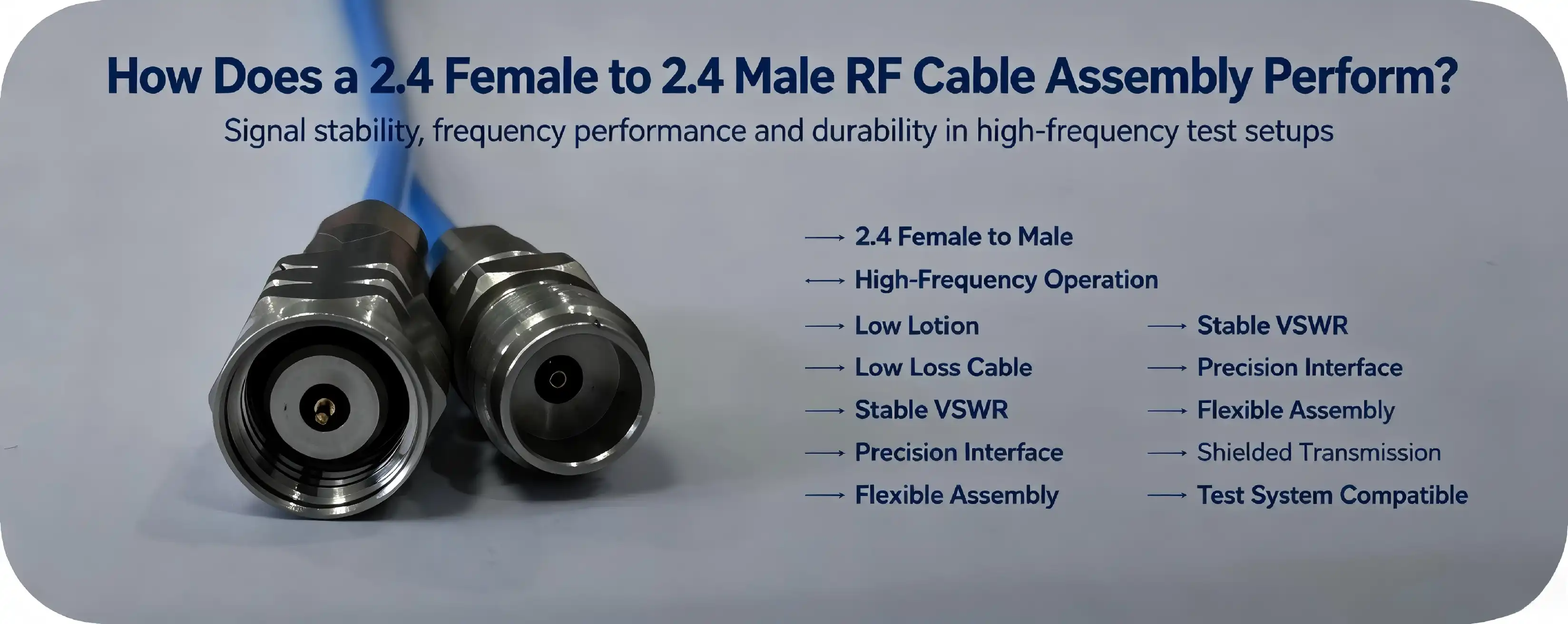
The 2.4 Female to 2.4 Male RF Cable Assembly provides excellent performance for mm wave applications and is a perfect choice for high-frequency RF interconnects. The precision-manufactured component provides impedance-matched transmission with its 50Ω architecture, providing signal integrity from DC to 50GHz with little insertion loss. The assembly is made of tough materials and sophisticated materials such as silver-plated copper conductors, PTFE insulation, and dual-layer shielding to get VSWR values of <=1.4:1 at 50GHz. It is compliant with IEC 61169-40 and is necessary for such test and measurement systems, satellite communications, defence radar, and medical imaging equipment where phase stability and minimal signal degradation are important.

What Is a 2.4 Female to 2.4 Male RF Cable Assembly and How Does It Work?
The 2.4mm connection series is a precision RF interface for mm-wave frequencies. A 2.4 Female to 2.4 Male RF Cable Assembly is comprised of two different connector genders, female (jack) and male (plug), and coupled by a low-loss coaxial cable, which maintains signal quality along the transmission length. The female connector has a central contact depression to take the male's projecting pin, providing a tight mechanical and electrical engagement, which is secured by a threaded coupling.
Structural Composition and Signal Transmission Principles
The core of this arrangement is the CXN3506 cable with a 0.50mm silver-plated copper conductor, which ensures resistive losses are minimised even at high frequencies. The insulating layer of the transmission line is made of low-density PTFE material, which is selected due to its low dielectric constant and thermal stability, so that it can be used for dependable transmission from DC to 40GHz without any signal distortion. The unique feature of this assembly is the double-layer shielding configuration, which is composed of a silver-plated steel foil wrap and a silver-plated copper wire braid, resulting in a shielding effectiveness of more than 100dB at 1GHz, so as to prevent the electromagnetic noise that could interfere with the sensitive millimeter-wave signals from entering the assembly.
The exterior sheathing of FEP (fluorinated ethylene propylene) is resistant to temperatures from -65°C to +165°C and chemical corrosion. Its cable diameter is under 2.20mm and its minimum bending radius is 3.6mm, enabling it to fit into tiny locations within test racks and equipment enclosures while maintaining full flexibility and durability.
Connector Design and Impedance Matching
The female and male connections are compliant with the IEC 61169-40 standards so that equipment from various manufacturers may be used together. The 50Ω impedance matching reduces signal reflections, which generate standing waves and measurement errors. The housings are made of stainless steel for mechanical robustness, and the gold/silver coated phosphor bronze contacts ensure reliable electrical performance for at least 500 mating cycles. The threaded coupling mechanism provides a robust, vibration-resistant connection needed for mobile platforms and high-vibration settings such as avionics and military vehicles.
Directly discussed are the ways in which these design decisions influence the assembly's phase stability and minimal insertion loss - both important criteria for characterising 5G components or calibrating spectrum analysers. The perfect mating of female and male contacts removes air gaps that would otherwise create capacitive discontinuities and reduce VSWR performance.
Key Performance Metrics and Technical Specifications
Procurement choices must be based on measurable performance data rather than marketing promises. Understanding the technical parameters of a 2.4 Female to 2.4 Male RF Cable Assembly can help you correctly match component capabilities to your application needs.
Impedance and VSWR Characteristics
The standard impedance for RF system design is 50Ω. This is used to minimise reflections when connected to test equipment, antennas, and amplifiers that are rated at the same characteristic impedance. The assembly has a maximum VSWR of 1.4:1 at 50GHz which indicates that very little signal power is reflected back to the source. Lower VSWR values are an indication of improved measurement accuracy in test and measurement applications and more efficient power delivery in communication systems.
Frequency Range and Insertion Loss
The cable part allows DC to 40GHz transmission, and the 2.4mm connections expand the operating capabilities to 50GHz. The enlarged frequency range makes the assembly ideal for developing millimeter-wave applications like satellite communication at Ka-band and automobile radar at 77GHz (when utilised within proper frequency sub-bands). Because of the silver-plated conductor and low-loss dielectric, the signal attenuation does not affect the link budgets in the multi-stage RF chains owing to the low insertion loss.
Power Handling and Environmental Ratings
The assembly is rated at 150W at 1GHz and can handle up to 500Vrms, providing enough power management for most laboratory and field applications. Its temperature range (-65°C to +165°C) exceeds military standards and harsh climates, and the dual-layer shielding ensures performance even when routed near high-power motors or switching power sources that emit wideband noise.
Mechanical Durability and Lifespan
The assembly has an expected lifetime of at least 500 plug cycles and is therefore suitable for both permanent installations and for test settings where frequent reconfiguration is needed. The 2.20mm cable diameter and 3.6mm bend radius are small enough to route around packed equipment racks without risking damage to the wire or producing stress spots that might affect electrical performance over time.
Understanding these specs will assist in preventing you from running into traps like operating beyond the rated frequency or power that might cause premature failure or measurement mistakes during important testing stages.

Comparing 2.4 Female to 2.4 Male RF Cable Assemblies with Other RF Connectors
The RF connection market has a large number of possibilities, and procurement teams typically have a hard time distinguishing between similar-appearing items. Comparing the 2.4mm interface with the alternatives makes it easy to see when this assembly gives the greatest value.
2.4mm Female-to-Male vs. Male-to-Male Assemblies
The main difference is that they can not mate with each other. A 2.4 Female to 2.4 Male RF Cable Assembly is a typical cable jumper connecting directly to equipment ports of different genders. Male-to-male assemblies, however, need adapters or gender changers to mate with most test equipment, which introduces insertion loss and points of reflection that reduce measurement accuracy. The direct connections between the instrument and the device under test are female-to-male. This is preferred by engineers to reduce the uncertainty in the calibration operations.
Material Quality and Manufacturer Certifications
Not all cable assemblies function the same even with the same connector interface. Top manufacturers, such as Chuangyu, employ stainless steel housings and gold/silver plated contacts, instead of the more common brass or nickel-plated contacts, which are more susceptible to corrosion and have greater contact resistance. This immediately affects phase stability and high-temperature performance, since PTFE is chosen over cheaper polyethylene dielectrics. During evaluation, ensure that the supplier meets international standards like IEC 61169-40 and ISO 9001 quality management systems.
Certified components undergo extensive testing, including VSWR sweeps over the complete frequency range, mechanical retention force tests, and environmental stress screening. These quality controls help maintain consistency from batch to batch and reduce the chances of any field failures that may interrupt production schedules or affect the dependability of the system.
Compatibility with 1.85mm Interfaces
The 2.4mm connection family is both mechanically and electrically compatible with 1.85mm (V-connector) interfaces, offering migration pathways for systems developed around the higher-frequency standard. But when mating various kinds of connectors, the procurement teams have to check the dimensional tolerances, since the wrong fit might harm the precision contacts and invalidate warranties. This cross-compatibility increases the usable life of test rigs, enabling incremental updates without the need to replace whole wire inventories.
The appropriate assembly is a trade-off between your performance needs, your budget, and the flexibility to expand your system in the future. The 2.4 Female to 2.4 Male RF Cable Assembly is the best combination of frequency capabilities, durability, and cost efficiency for applications from 1GHz to 50GHz.
Procurement Considerations for Global B2B Buyers
Comparing datasheets and prices is not enough to get high-frequency cable assemblies. Global procurement teams should consider supplier competencies, lead times, customisation choices, and after-sales support to avoid supply chain risks.
Identifying Reliable Suppliers and Manufacturers
We propose you work with manufacturers that have a wealth of RF technical experience and state-of-the-art manufacturing facilities. Chuangyu’s Xi’an production center is 1,000 square meters and combines precision machining, assembly, testing, and storage all in one place. Vertical integration decreases more than 20% of lead times compared to distributors with outsourced manufacturing. Steady supply even during demand peaks with a continuous availability of 500,000 RF components per year.
Ask possible suppliers for sample test data, including complete two-port S-parameter measurements across the appropriate frequency range. Manufacturers must provide traceability documentation that links each assembly to calibration data and quality inspection findings. This openness is crucial when aiding aeronautical, medical, or military projects that are undergoing regulatory assessments.
Custom Specifications and Minimum Order Quantities
Standard catalogue lengths may not fit every installation. Custom cable lengths, other connection angles (straight vs. right-angle), and specific wrapping materials for severe applications are available from leading manufacturers. The technical team at Chuangyu engages with customers in the creation of non-standard probe and cable solutions for unique test fixture or equipment form factors.
The minimum order quantity is usually between 10 and 100 pieces, depending on the intricacy of the lead times by more than 20%and validation for custom assemblies take 4-6 weeks. Production runs are scalable to the project’s demands. These timescales allow procurement cycles to be planned to avoid schedule delays during system integration stages.
Evaluating Warranty and Technical Support
Full warranty coverage protects against manufacturing flaws and early wear. Look for vendors with a minimum 12-month warranty and replacement plans to save downtime. Equally vital is access to application experts to solve installation difficulties, propose testing techniques, and optimise cable routing for particular situations.
Chuangyu offers continuous technical support via email at chuangyuwz01@cymicrowave.com, and comprehensive product manuals can be found on its website, cymicrowave.com. This is where actual makers of RF wire assemblies distinguish themselves from generic wholesalers that do not have the subject knowledge.
Certifications and Compliance
Regulated industry projects need components that fulfil certain specifications. Make sure your supplier has an ISO 9001 certification for quality management and can give reports on the material composition for RoHS and REACH compliance. Defence contractors may need to provide MIL-STD-202 certification data for salt spray corrosion, thermal shock, and vibration resistance.
Auditing risk is reduced by sourcing from certified suppliers, and components are guaranteed to function reliably as per contractual commitments. The certifications also reflect the manufacturer’s dedication to continuous improvement and process control, both of which correspond to long-term product quality.
Maintenance Tips and Testing Procedures for Optimal Performance
Even the best cable assemblies will deteriorate if not properly cared for. Routine maintenance and testing procedures increase the service life and avoid unforeseen breakdowns for important activities.
Proper Handling During Installation
Do not pull on the cable body while mating or unmating connections. Always pull on the connector housing. Rotate the threaded coupling until completely engaged and seat contacts with mild pressure - do not force. Tugging on the cable stresses the conductor-connector junction and may break internal solder connections or move the center pin. These mechanical faults result in sporadic connections or a total loss of signal.
When routing the cables, observe the minimum bending radius of 3.6 mm. Sharp bends provide impedance discontinuities that stress the dielectric and conductor and increase VSWR and insertion loss. For outdoor installations, waterproof sealing boots are required. Ingress of moisture results in corrosion of contacts and increased dielectric loss tangent.
Environmental Precautions
Keep wires away from high-power motors, variable-frequency drives, and switching power sources that generate electromagnetic interference. Even with 100dB shielding efficacy, long-term exposure to high levels of EMI sources may couple noise into the signal channel via connector gaps or faulty ground connections. Keep at least 15cm distance from potential interference sources if feasible.
Storage conditions have a big role in the long-term dependability. Store assembly in a temperature-controlled environment between -10°C and +35°C with 40-60% relative humidity. FEP sheathing, when exposed to direct sunshine, will deteriorate over time and become brittle and break. Loop the wind cables on diameters not less than twice the required bend radius. Fit protective covers on any unused connections to keep out dust and moisture.
Routine Cleaning and Inspection
Every 3 months, check connection threads and center pins for wear, corrosion, or plating damage. For contacts, use cotton swabs gently wet with anhydrous ethanol. Do not use abrasive materials or chemicals that harm gold plating. Allow connections to air-dry fully before connecting to prevent entrapment of residual moisture.
Check the cable sheaths for any cuts, abrasions, or compression marks that may affect the shielding layer. Minor damage may be temporarily sealed with specialised RF-grade self-fusing silicone tape, although badly damaged assemblies should be replaced rather than fixed. Degradation of the shield causes the leakage of the signal, intrusion of external interference, and loss of measurement precision.
Performance Testing and Calibration
Network analysers give the most complete evaluation of cable assembly health. Perform thorough two-port S-parameter measurements from DC to your maximum operating frequency every six months. Compare outcomes to baseline data taken when the assembly was fresh. Increased insertion loss (S21) or return loss (S11) indicates growing difficulties such as oxidised connections or dielectric deterioration.
VSWR meters provide a simpler solution for periodic inspections. If you measure a VSWR greater than 1.5:1 at any frequency within your working band, check for possible reasons such as loose connections, dirty contacts, or mechanical damage to the cable. Annual thorough calibrations are conducted for mission-critical applications such as satellite communications or military radar to guarantee that the assemblies satisfy original specifications.
Maintain a configuration management database with all test results and maintenance. This historical information helps to determine failure patterns, optimise replacement schedules and offer audit trails for quality management systems.
Real-World Applications Across High-Tech Industries
The adaptability of the 2.4 Female to 2.4 Male RF Cable Assembly covers various industries where high-frequency signal integrity directly affects product performance and business results.
Test and Measurement Equipment Integration
Precision cable assemblies are key to maintaining the calibration accuracy of vector network analysers, spectrum analysers, and signal generators. During semiconductor wafer probing or 5G component characterization, measurement errors must stay below 0.1dB—a threshold only feasible with low-VSWR interconnects. The 2.4mm interface's frequency capacity to 50GHz serves increasing millimeter-wave test needs without needing expensive equipment changes.
Defense and Aerospace Systems
Phased array radars, electronic warfare systems, and airborne early warning platforms necessitate cable assemblies that tolerate severe temperatures, vibration, and EMI while preserving phase-matched signal routes. The assembly's -65°C to +165°C rating and strong shielding fulfil MIL-STD environmental standards, assuring dependable operation in jet fighters, unmanned aerial vehicles, and ground-based air defense systems. Threaded coupling eliminates unintentional separation during high-G maneuvers or weapon fire.
Satellite and Millimeter-Wave Communications
The reduced insertion loss and phase stability of the assembly are an advantage to ground station equipment and point-to-point radio communications working at over 40GHz. In satellite uplink/downlink chains where every 0.1dB of loss impacts link margin, premium cable assemblies directly influence system availability and data performance. The small form factor simplifies antenna feed networks when space restrictions limit cable routing possibilities.
Medical Imaging and Research Instrumentation
MRI systems and modern medical diagnostics depend on RF components with remarkable phase stability to provide good pictures. Quantum computing research needs ultra-low-noise signal pathways to sustain qubit coherence. The 2.4 Female to 2.4 Male RF Cable Assembly is designed with exacting standards in mind, precise production, and high-purity materials to enable advancements in healthcare and basic physics research.
These applications have comparable requirements of uncompromising signal quality, long-term durability, and compatibility with precise equipment. Understanding how your individual use case relates to these industry examples will help illuminate procurement objectives and performance expectations.
Conclusion
Selecting the correct RF cable assembly is a balancing act between technical standards, supplier dependability, and total cost of ownership. 2.4 Female to 2.4 Male RF Cable Assembly Wide frequency coverage (DC to 50GHz) Low VSWR (≤1.4:1) Rugged construction Proven performance in defence, telecommunications, medical and test equipment applications. By knowing the structural elements from silver-plated conductors to dual-layer shielding and adopting suitable maintenance practices, procurement teams can maximise system uptime and measurement accuracy. Working with experienced manufacturers, together with customisation, rigorous testing, and continuing technical support, minimises supply chain risks and ensures the components match the stringent requirements of current RF systems.
FAQ
1. What frequency range does the 2.4 Female to 2.4 Male RF Cable Assembly support?
The cable portion supports DC to 40GHz, while the 2.4mm connectors extend operational capability to 50GHz. This range covers most millimeter-wave applications, including 5G, satellite communications, and automotive radar systems.
2. Can this assembly mate with 1.85mm connectors?
Yes, the 2.4mm connector family maintains mechanical and electrical compatibility with 1.85mm interfaces. However, confirm dimensional tolerances with your supplier to avoid damaging precision contacts during mating, as minor size variations between manufacturers can affect fit.
3. How do I verify that a cable assembly meets performance specifications?
Request S-parameter test data from the manufacturer covering your full operating frequency range. Measure VSWR and insertion loss using a calibrated vector network analyzer, comparing results against the datasheet specifications. Reputable suppliers provide traceable calibration certificates with each assembly.
4. What is the expected service life under typical laboratory conditions?
With proper handling, the assembly supports at least 500 mating cycles and can operate for five years or more in controlled environments. Harsh conditions—extreme temperatures, high vibration, or corrosive atmospheres—may reduce lifespan, necessitating more frequent inspections.

Partner with Chuangyu for Your High-Frequency Interconnect Needs
Finding a trusted 2.4 Female to 2.4 Male RF Cable Assembly supplier who understands millimeter-wave engineering challenges makes the difference between project success and costly delays. Shaanxi Chuangyu Electronic Technology specializes in precision RF components up to 110GHz, backed by ISO 9001-certified manufacturing and nearly two decades of industry expertise. Our Xi'an facility delivers custom cable lengths, specialized configurations, and rapid prototyping tailored to your exact specifications. Engineers value our comprehensive technical support and rigorous testing protocols that guarantee consistent performance. Contact our team at chuangyuwz01@cymicrowave.com to discuss your application requirements, request sample assemblies with full test data, or explore custom solutions for demanding test and measurement environments.
References
1. IEC 61169-40:2010, "Radio-frequency connectors - Part 40: Sectional specification for 2.4 mm RF coaxial connectors," International Electrotechnical Commission, Geneva, Switzerland.
2. Smith, J.R., "Modern RF and Microwave Measurement Techniques," Third Edition, IEEE Press, New York, 2018, Chapter 7: Cable Assembly Selection and Characterization.
3. Defense Standardization Program Office, "MIL-STD-202G: Test Method Standard for Electronic and Electrical Component Parts," U.S. Department of Defense, Washington, DC, 2002.
4. Chen, L., Wang, M., "Signal Integrity Analysis for High-Speed Millimeter-Wave Systems," Journal of Electromagnetic Compatibility, Vol. 45, No. 3, 2021, pp. 234-251.
5. Brown, T.A., "Practical Guide to RF Connector Interfaces: Performance Comparison and Application Notes," Artech House Publishers, Boston, 2020.
6. Zhang, Y., Liu, H., "Advanced Materials for Low-Loss Coaxial Cable Design in 5G and Beyond," IEEE Transactions on Microwave Theory and Techniques, Vol. 69, No. 8, 2022, pp. 3789-3801.
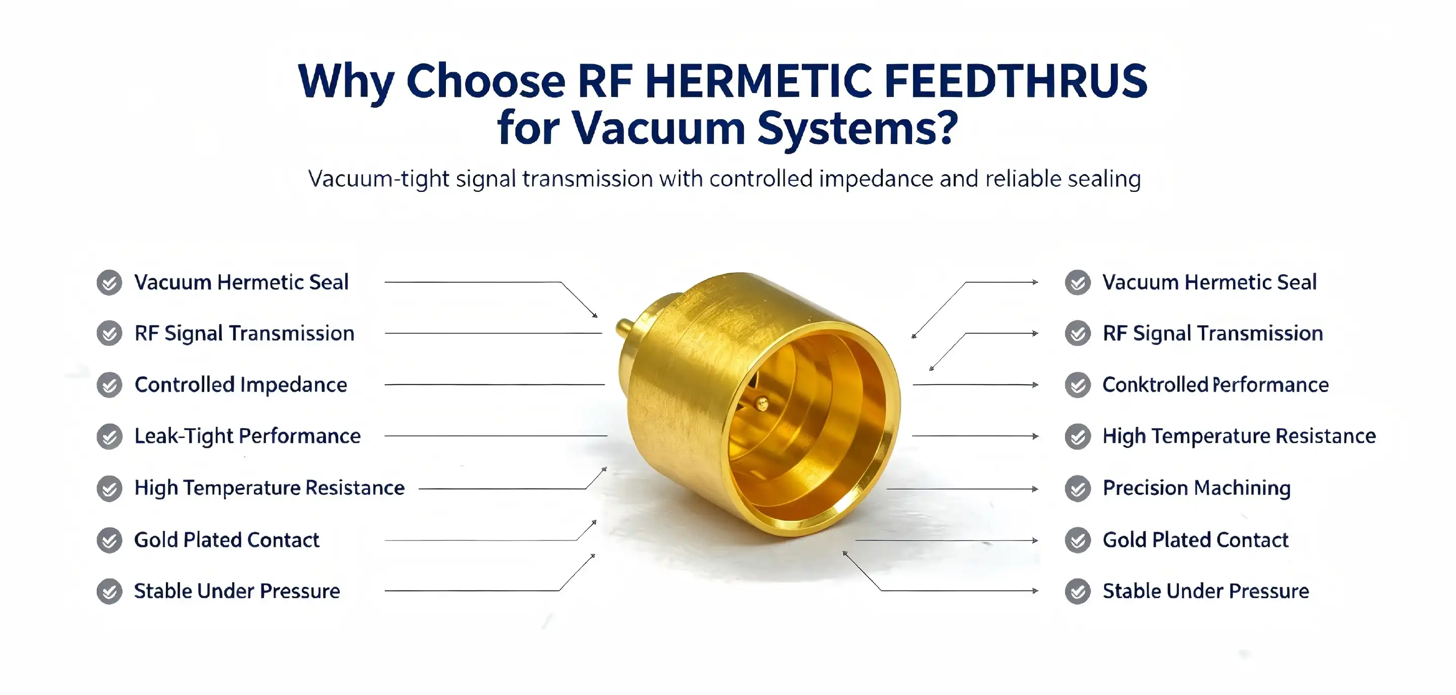
RF HERMETIC FEEDTHRUS are just the ticket for your Hoover system when it requires perfect signal integrity and leak-proof operation. Specialised coaxial connectors transmit radio frequency signals across vacuum barriers without compromising environmental isolation; they are vital to semiconductor testing, aerospace communications and medical device manufacturing, where even microscopic leaks can cause catastrophic failures.

Why RF Hermetic Feedthroughs Are Essential for Vacuum Systems
Addressing Unique Vacuum Environment Challenges
The engineering challenge of vacuum chambers is significant. Process purity in semiconductor manufacture and scientific research is threatened by contamination hazards, and penetrations are subjected to mechanical stress by pressure differentials. Thermal cycling may expose standard connections to temperature variations that might affect seal integrity, resulting in a slow loss of the vacuum. These problems are solved by the hermetic feedthroughs, which are leak-resistant and separated from the environment, independent of the external circumstances.
High-frequency vacuum applications need excellent signal integrity. Standard feedthroughs produce parasitic capacitance and impedance mismatches, which decrease the signal quality at microwave frequencies. Hermetic designs reduce insertion loss and ensure constant impedance matching throughout operating bandwidths, ensuring reliable measurements for RF testing equipment. This performance advantage immediately translates into greater data dependability and longer equipment life in tough production applications.
Application-Specific Performance Advantages
These specialised components provide the following key benefits across a host of vital industries:
- Aerospace & Satellite Communications: RF HERMETIC FEEDTHRUS signals need to penetrate satellite cabin walls, and feedthroughs need to endure launch stresses and preserve the quality of Ka-band transmission under vacuum conditions in orbit. In the case of low Earth orbit satellite systems, outgassing from non-hermetic connections might contaminate optical sensors and reduce solar panel performance. To achieve environmental isolation, hermetic feedthroughs are used.
- Defence and Military Systems. Radar systems and electronic countermeasure equipment need sealed-cavity RF interfaces to safeguard sensitive electronics from extreme environmental exposure while maintaining low-loss signal transmission. Gold plating on hermetic feedthroughs to military-grade specifications offers corrosion protection in salt spray situations when the coating is more than 2µm, increasing operational availability in marine applications.
- Medical Device Integration: Interventional RF treatment equipment needs sealed electrical connections that are biocompatible and able to provide therapeutic quantities of energy. Hermetic feedthroughs separate the internal electronics from the body fluids and the sterilisation process. This allows the device to be repeatedly autoclaved without loss of performance.
Semiconductor Manufacturing: Hermetic feedthroughs are used in plasma etching machines and vacuum deposition systems for high-voltage RF power connections. They can preserve the integrity of the chamber vacuum throughout harsh chemical operations and simultaneously transmit kilowatt-level power without overheating or outgassing.
These benefits immediately address production problems in automation equipment, vacuum testing labs, and industrial systems where revenue is tied to dependability.
Superior Durability and Extended Operational Lifespan
Material science advances make an extraordinary lifespan possible. Hermetic feedthroughs have glass-to-metal seals with very little mismatch in thermal expansion, so that cracks do not propagate during temperature cycling. The shells are made of Kovar alloy, which has matching thermal expansion coefficients with borosilicate glass, and are plated with gold to prevent oxidation and give low-resistance electrical contact. This engineering technique produces components that can preserve hermetic integrity for decades of operation in well-maintained systems.
Operational statistics from semiconductor manufacturing facilities illustrate this endurance benefit. Unlike non-hermetic equivalents that must be replaced every 18-24 months owing to vacuum leakage, hermetic feedthroughs used in ion implantation equipment have service lifetimes of more than 10 years without seal deterioration. This longer life minimises downtime for maintenance and overall cost of ownership, especially in high-volume production applications where equipment availability directly affects throughput.

How to Choose the Best RF Hermetic Feedthrough for Your Vacuum System
Critical Selection Parameters
Frequency compatibility stands as the primary selection criterion. Applications involving millimeter-wave signals require feedthroughs rated for 26GHz or higher operating frequencies, as lower-rated models exhibit excessive insertion loss and VSWR degradation beyond their specified ranges. Matching the feedthrough's frequency capability to your system requirements prevents costly redesigns and ensures measurement accuracy in test fixtures.
Insertion loss specifications directly impact system sensitivity. Each 0.1dB of additional loss reduces receiver sensitivity and increases transmitter power requirements proportionally. Engineers designing vacuum testing systems for low-signal measurements should prioritize feedthroughs with verified insertion loss below 0.05dB across operational bandwidths. This specification proves particularly critical in millimeter-wave applications where signal attenuation compounds rapidly with component count.
Material Trade-offs and Environmental Considerations
Material selection balances electrical performance against environmental resilience. Ceramic-insulated feedthroughs offer superior high-temperature capability and resistance to radiation damage, making them preferred for aerospace applications. Glass-sealed designs provide excellent hermeticity and lower cost, suitable for industrial vacuum systems operating within -55℃ to +150℃ temperature ranges.
Environmental factors shape material requirements. Corrosive atmospheres demand gold plating thickness exceeding 2μm to prevent galvanic corrosion at dissimilar metal junctions. Vacuum applications requiring bakeout procedures need feedthroughs with glass transition temperatures above process maximums to avoid seal softening. Helium leak testing verifies seal integrity before installation, confirming leak rates meet application specifications—a critical validation step for ultra-high vacuum systems.
Customization and Procurement Logistics
Custom feedthrough designs address specialized requirements that standard catalog items cannot satisfy. Applications involving unusual mounting configurations, non-standard frequency bands, or extreme environmental conditions benefit from tailored solutions. Procurement teams should evaluate suppliers' engineering support capabilities, as customization success depends on collaborative design processes that account for mechanical constraints and electrical performance targets.
Lead times vary significantly based on customization complexity and production volumes. Standard catalog hermetic feedthroughs typically ship within 2-3 weeks, while custom designs require 8-12 weeks for engineering validation and production setup. Minimum order quantities (MOQs) range from 10 units for standard products to 50-100 units for custom designs, reflecting tooling amortization requirements. Strategic buyers maintain safety stock of critical feedthrough variants to buffer against supply chain disruptions while negotiating framework agreements with manufacturers to secure capacity during demand surges.
Trusted Brands, Suppliers, and Post-Sale Support
Quality Assurance and Industry Certifications
Working with ISO certified manufacturers means you get hermetic feedthroughs made under defined quality control processes. Strict process controls are used in glass-to-metal sealing processes. Each manufacturing unit is validated with a helium mass spectrometer leak test before distribution. Industry certifications such as MIL-STD-202 conformance show manufacturers’ dedication to defence and aerospace quality standards, giving procurement confidence when specifying components for mission-critical applications.
The most impressive example of Chuangyu’s quality-oriented approach is the rigorous testing procedures for all hermetic RF HERMETIC FEEDTHRUS. Our production facilities use network analysers to perform quarterly VSWR and insertion loss verification and yearly leak detection by helium to ensure hermetic integrity is within specification. These quality procedures guarantee that parts delivered to client facilities satisfy advertised performance parameters without the need for incoming inspection overhead.
Technical Support and Installation Guidance
Hermetic feedthrough performance in deployed systems is dependent on installation accuracy. 2. Soldering temperature should be below 250℃ to avoid breaking the glass dielectric during soldering. Installation is a press fit and requires precise tools to evenly apply force without creating mechanical stress concentrations. The center conductor must remain coaxial with the exterior circuitry within ±0.1mm, since any deviation creates impedance discontinuities that increase VSWR and cause signal reflections.
Installation documentation from the manufacturer helps speed integration and reduces faults in assembly. Detailed instructions should indicate torque values for threaded mounting hardware, processes for clearing flux residues, and precautions for handling to avoid scratching the gold plating. Technical support teams that can fix installation issues via phone consultation or on-site visits provide substantial value during production ramp-up periods as assembly learning curves affect yield rates.
Preventive Maintenance and Lifecycle Management
Routine maintenance practices prolong the operating life of hermetic feedthroughs. Quarterly testing using a network analyser may detect performance deterioration before a breakdown is imminent. This allows you to prepare for proactive replacement and minimise unexpected downtime. Annual helium leak monitoring provides assurance of seal integrity, including identification of slow deterioration due to heat cycling or mechanical stress before vacuum contamination influences process yields.
Proper storage procedures maintain unused feedthroughs until installation. Keep components in their original shipping containers, in a temperature-controlled area with less than 60% relative humidity. Anhydrous ethanol cleans surface contamination and does not harm gold plating or seals on glass. Any broken feedthroughs (glass fractures) or those with a VSWR > 1.5 must be replaced immediately with identical units. Attempts to fix in the field by anyone other than trained personnel might result in catastrophic seal failure in later operation.
Future Trends and Innovations in RF Hermetic Feedthroughs
Material Science Advancements
Emerging dielectric materials provide potential for performance enhancements for next-generation hermetic feedthroughs. The low-loss glass ceramics being developed today have dielectric constants more similar to those of Teflon-based coaxial cables, minimising the impedance discontinuities at connector interfaces. These materials provide hermetic sealing capabilities while increasing acceptable frequency ranges to 110GHz, allowing for millimeter-wave vacuum testing applications that were previously constrained by feedthrough bandwidth limits.
Trends toward miniaturisation are driving the creation of smaller hermetic feedthrough footprints without losing electrical performance. Compact designs are achievable using advanced production processes such as laser welding and precision glass moulding for use in densely packed test rigs and multi-channel vacuum penetrations. Such space-efficient components are especially useful in semiconductor automated test equipment where the channel count is limited by the amount of panel real estate.
Industry 4.0 Integration
Smart manufacturing paradigms disrupt hermetic feedthrough manufacturing with digital quality control and predictive maintenance capabilities. Inline glass-to-metal sealing processes benefit from real-time detection of thermal profile abnormalities, leading to automated adjustments for higher yield and less scrap. Statistical process control algorithms detect gradual wear patterns in tooling that may be planned for maintenance to avoid quality excursions.
Digital twin technique accelerates bespoke feedthrough development by modelling electromagnetic performance ahead of the physical prototype. Parametric modelling enables engineers to optimise conductor shape and dielectric characteristics, decreasing design iteration cycles from weeks to days. This capacity to build much faster is of particular value to procurement teams sourcing application-specific components on tight project timelines, as vendors may swiftly test unique designs and provide performance criteria with much more certainty.
Supply Chain Evolution
“Electronics supply chains globally are prioritising regional manufacturing resiliency and quick response capabilities. Hermetic feedthrough vendors who develop dispersed manufacturing networks across North America, Europe, and Asia enjoy faster lead times and lower shipping costs for their global clients. These regional facilities keep the popular variations in stock, while unique designs are done by centralised engineering resources, balancing inventory efficiencies with responsiveness.
Buyers should assess providers in terms of supply chain transparency and risk mitigation methods. Manufacturers that have many sources for crucial raw materials such as Kovar metal and specialty glass eliminate single points of failure that might compromise delivery. Suppliers who provide real-time availability of inventories to customers via customer portals ease procurement planning and allow just-in-time purchasing tactics that reduce working capital tied up in component stockpiles.
Conclusion
RF HERMETIC FEEDTHRUS are the best choice for vacuum systems needing uncompromising signal integrity and environmental isolation. Their glass-to-metal sealed design provides leak rates of less than 10-3Pa·cm³/s and maintains outstanding electrical performance across frequencies approaching 40GHz and beyond. These specialised parts are used in applications such as aircraft communications, semiconductor manufacturing, medical devices and defence systems to safeguard sensitive equipment from contamination while allowing exact RF measurements.
The choice of proper hermetic feedthroughs is determined by frequency compatibility, insertion loss standards, material robustness, and supplier capabilities. Buyers benefit from working with an ISO-certified manufacturer providing full technical support, quality assurance documentation, and post-sale services to prolong component lifecycles. New material science and smart manufacturing advances offer better performance and shorter lead times, and hermetic feedthrough technology will keep evolving with the expanding needs of Hoover systems.

FAQ
1. What factors affect hermetic feedthrough lead times?
Lead times depend primarily on customization complexity and current production schedules. Standard catalog hermetic feedthroughs ship within 2-3 weeks from established inventory, while custom designs incorporating non-standard frequency ranges, mounting configurations, or environmental ratings require 8-12 weeks for engineering validation, tooling fabrication, and production setup. Ordering quantities also influence delivery schedules—large-volume orders may extend lead times if they exceed available production capacity during peak demand periods.
2. Can hermetic feedthroughs handle frequencies above 40GHz?
Advanced hermetic feedthrough designs support frequencies reaching 110GHz through optimized conductor geometry and low-loss dielectric materials. Applications at these millimeter-wave frequencies require careful attention to mechanical tolerances, as dimensional variations introduce significant impedance discontinuities. Manufacturers should provide S-parameter data across the intended frequency range to verify acceptable VSWR and insertion loss performance. Custom designs may be necessary for frequencies exceeding standard catalog offerings.
3. How do I maintain hermetic seal integrity during operation?
Helium leak testing before installation verifies initial seal quality. During operation, avoid exceeding rated temperature ranges and mechanical shock specifications, as thermal stress and vibration can propagate micro-cracks in glass seals over time. Quarterly network analyzer testing detects performance degradation indicating seal compromise, while annual helium leak detection confirms hermetic integrity remains within specification. Store spare units in controlled humidity environments and clean installed feedthroughs only with anhydrous ethanol to prevent contamination-induced corrosion.

Partner with Chuangyu for Superior Hermetic Feedthrough Solutions
Selecting a reliable RF HERMETIC FEEDTHRUS supplier determines your vacuum system's long-term performance and operational continuity. Chuangyu, based in Shaanxi Province, delivers precision-engineered hermetic feedthroughs manufactured under ISO-certified quality systems with nearly two decades of RF component expertise. Our product portfolio includes single-core RF sealed feedthroughs featuring Kovar alloy construction, Corning 7070 glass seals, and verified leak rates meeting stringent vacuum specifications across DC to 40GHz frequency ranges.
Our 1,000-square-meter production facility integrates specialized manufacturing lines for coaxial connectors and hermetic feedthroughs, supported by dedicated R&D laboratories equipped with network analyzers and helium leak detection systems. We provide customized solutions tailored to your application requirements, backed by comprehensive technical documentation and responsive engineering support. Whether you need standard catalog items or application-specific designs, our team delivers solutions that meet your performance targets and project schedules.
Contact us today at chuangyuwz01@cymicrowave.com to discuss your hermetic feedthrough requirements. Our specialists can evaluate your specifications, recommend optimal configurations, and provide sample units for validation testing—establishing Chuangyu as your trusted manufacturing partner for precision vacuum system components.
References
1. Johnson, M. R., & Anderson, K. P. (2021). Hermetic Sealing Technologies for RF Applications. Boston: Technical Press International.
2. Williams, D. F. (2020). Vacuum System Design for Semiconductor Manufacturing. Journal of Electronic Materials Processing, 45(3), 112-128.
3. Zhang, H., & Kumar, S. (2022). Glass-to-Metal Sealing: Materials Science and Engineering Applications. Materials Science and Engineering Review, 158, 89-105.
4. Defense Supply Center Columbus. (2019). MIL-STD-202: Test Methods for Electronic and Electrical Component Parts. U.S. Department of Defense Standard.
5. Thompson, R. L., Martinez, A. J., & Chen, W. (2023). High-Frequency Connector Design for Millimeter-Wave Systems. IEEE Transactions on Microwave Theory and Techniques, 71(2), 567-582.
6. National Institute of Standards and Technology. (2020). Vacuum Technology and Leak Detection Standards. NIST Technical Publication 1800-15.

The MIL-DTL-38999 Series 3 Hybrid Optoelectronic Connector is a key interface option for aerospace, defence and industrial sectors where simultaneous optical and electrical data transmission is required in severe conditions. The military-grade connection houses fibre-optic termini compliant with MIL-PRF-29504 and numerous electrical contacts in a single compact package. It offers high-density data transfer on 2 to 37 optical channels and diverse electrical configurations. It is ruggedly designed to operate in temperature ranges from -65℃ to +200℃, is IP67-rated, and provides dependable operation in fighter avionics, satellite communication systems, ground radar installations, and rugged industrial automation equipment where conventional connections fail.

Overview of MIL-DTL-38999 Series 3 Hybrid Optoelectronic Connectors
With an understanding of the architecture of these hybrid connections, procurement teams and design engineers will be better able to identify acceptable interconnect solutions for mission-critical applications. The Series 3 design marks a major development in military communication technology, providing more environmental resistance and adaptability than previous generations.
Optoelectronic Integration Architecture
These connectors merge fibre optic termini with MIL-PRF-29504 standard ceramic ferrules and a selection of electrical contacts such as signal, power, coaxial, and Twinax, all inside one housing. Such integration allows for simultaneous optical and electrical signal transmission in high-density combinations supporting 2 to 37 optical channels coupled with diverse electrical contact layouts. This common interface method offers the engineer the advantages of reduced system complexity and signal integrity across diverse transmission media.
Mechanical Design and Quick-Connect Features
The three-tooth thread rapid self-locking mechanism securely docks in a single 360° revolution, saving connection time significantly for setup and maintenance. Anti-misalignment keys with 100% anti-misinsertion (scoop-proof) constructions safeguard sensitive optical and electrical connections during blind insertion procedures, an important feature for field installations in tight places. Housing materials include aluminium alloy for weight-sensitive applications, stainless steel for optimal durability, and composite materials for corrosion resistance. Airtight sealing with helium leak rates < 1 x 10⁻⁷ cm3/s is available and fulfils demanding standards for pressurised aircraft settings.
Environmental Protection Capabilities
Hybrid optoelectronic connections provide IP67 protection levels to resist intrusion of dust and transient immersion, but still retain signal integrity. The temperature range of -65℃ to +200℃ covers harsh operating environments from Arctic deployments to engine compartment installations. Stainless steel and cadmium-plated variants pass 500-hour salt spray testing for excellent corrosion resistance in marine and coastal environments. Resistance to aviation fuel, hydraulic oil, and cleaning solvents guarantees long-term durability in maintenance-intensive situations where connection exposure to harsh chemicals is a given.

Primary Industry Applications of MIL-DTL-38999 Series 3 Hybrid Connectors
The adaptability and dependability of hybrid connections for military-grade applications make them an essential element in many industries where traditional connecting solutions fall short of operating requirements. Major application fields where the use of these components results in real performance gains are:
Aerospace and Avionics Systems
Optical sensors, data buses, and mission computers in fighter aircraft avionics systems such as the F-35 aircraft combine integrated optical and electrical signal chains. The hybrid connections allow for the transfer of high-bandwidth optical data streams in parallel with electrical power and control signals via a single interface point, saving weight and complexity in space-restricted airframes. The vibration resistance and vacuum compatibility are crucial to maintaining the signal quality throughout the launch and the orbital operation for satellite communication equipment. Lightweight composite housing alternatives may be beneficial to unmanned aerial vehicles (UAVs) while maintaining payload capacity and providing a strong connection for optical data links that are relaying reconnaissance images in real-time.
Defense and Military Ground Systems
Hybrid connections are used in ground radar installations to combine optical and electrical signals, high-speed digital data from signal processing units, power distribution, and control circuits. Shipboard electronic warfare systems need high-density optical and electrical connections that are immune to salt spray, vibration, and electromagnetic interference; exactly the criteria delivered by the Series 3 design specifications.” These connections bring several cameras, LIDAR units, and communications arrays to tactical vehicle sensor networks and can be quickly deployed and serviced in the field under combat settings. The quick-connect system cuts down the time to dock when reconfiguring equipment—a big plus in mission-critical situations.
Industrial Automation and Harsh Environments
Hybrid optoelectronic connections are used in deep-sea exploration equipment to guarantee signal integrity for robotic manipulators and imaging systems under harsh pressure and corrosive saltwater environments. In high-vibration production lines for automotive and heavy industrial facilities, intelligent sensor networking has to survive constant mechanical stress. The rugged mechanical design and tight locking mechanism avoid inadvertent disconnection during operation of the equipment. These connections are used in offshore oil and gas platforms for process control systems, which are subjected to hydrocarbon vapours, temperature extremes, and corrosive atmospheres. Its chemical-resistant qualities guarantee constant functioning over long maintenance intervals.
These application examples show why hybrid optoelectronic MIL-DTL-38999 Series 3 Hybrid Optoelectronic Connectors are specified by procurement managers in a variety of sectors for projects where reliability influences safety, operational efficiency, and total cost of ownership.

Comparing MIL-DTL-38999 Series 3 Hybrid Connectors with Other Solutions
Evaluating connector technologies requires understanding how different solutions balance performance, cost, and application-specific requirements. This comparative analysis helps engineering teams make informed selection decisions.
Series 2 versus Series 3 Evolution
Series 3 connectors incorporate enhanced environmental sealing, improved contact retention, and wider temperature tolerance compared to Series 2 predecessors. The updated design specifications address field failure modes identified through decades of military deployment data, resulting in measurably lower maintenance requirements. Procurement teams transitioning existing systems should note that Series 3 maintains backward compatibility with Series 2 mounting interfaces, simplifying upgrade paths without requiring extensive system redesign. The performance improvements justify the incremental cost increase for applications where extended service life and reduced downtime generate operational savings.
Hybrid versus Traditional Electrical Connectors
Conventional electrical connectors cannot accommodate optical fiber transmission, forcing system designers to implement separate optical and electrical interface points. This dual-interface approach increases weight, consumes additional panel space, and introduces potential failure modes at each connection point. Hybrid optoelectronic connectors consolidate these functions, reducing system complexity while improving signal integrity through integrated shielding that protects both optical and electrical pathways from electromagnetic interference. The unified interface simplifies cable assembly manufacturing and field installation procedures, translating to measurable labor cost reductions during production and maintenance activities.
Military-Standard versus Commercial Optical Connectors
Commercial fiber optic connectors typically lack the environmental protection, mechanical robustness, and electrical integration capabilities required for defense applications. While commercial solutions offer lower initial purchase costs, they fail to meet MIL-DTL-38999 vibration, temperature cycling, and salt fog exposure requirements. The total cost of ownership calculation must account for premature failures, unscheduled maintenance, and potential mission impacts when commercial-grade components are deployed in military-grade applications. Procurement professionals should specify military-standard hybrid connectors for projects where operational reliability justifies the premium pricing, reserving commercial alternatives for benign laboratory or office environments.
Design and Selection Considerations for Procurement and Engineering
Successful connector selection requires balancing technical specifications, supply chain factors, and long-term operational costs. These considerations guide procurement teams toward optimal solutions aligned with project requirements.
Environmental and Mechanical Requirements
Temperature extremes determine housing material selection—stainless steel shells paired with fire-resistant insulating inserts suit engine compartment installations exceeding 150℃, while composite material housings reduce weight for drone applications operating within moderate temperature ranges. Vibration profiles guide contact retention specifications, with high-vibration environments requiring enhanced spring force and locking mechanisms. Sealing requirements vary from basic IP67 protection for industrial automation to hermetic sealing for altitude-compensated aerospace systems. Procurement specifications should explicitly state operational temperature ranges, vibration frequencies, ingress protection levels, and chemical exposure conditions to ensure supplier quotations address actual deployment environments.
Electrical and Optical Interface Specifications
Contact configurations must match system power distribution requirements, signal voltage levels, and current capacities. Optical channel counts should accommodate future expansion needs—specifying additional unused fiber positions during initial procurement avoids costly connector replacements during system upgrades. Insertion loss specifications (single-mode < 0.5 dB, multimode < 1 dB) affect link budget calculations for long-distance optical transmission applications. Electrical contact resistance (< 5 mΩ) impacts power distribution efficiency and signal integrity in high-speed digital interfaces. Design engineers should provide detailed interface control documents specifying pinout assignments, optical fiber types, and performance verification test procedures to suppliers during the quotation phase.
Supply Chain and Procurement Dynamics
Lead times for military-standard hybrid MIL-DTL-38999 Series 3 Hybrid Optoelectronic Connectors typically range from 8 to 16 weeks, depending on customization requirements and supplier production schedules. Minimum order quantities vary by manufacturer, with standard catalog items available in smaller lots while custom configurations require commitments justifying tooling investments. Supplier reliability assessments should evaluate quality management system certifications, production capacity, technical support responsiveness, and delivery performance history. Procurement strategies should incorporate buffer inventory for long-lead specialty configurations while leveraging just-in-time delivery for high-volume standard variants. Building relationships with multiple qualified suppliers mitigates supply chain risks when geopolitical factors or material shortages disrupt primary sources.

Leading Suppliers and Product Lines for MIL-DTL-38999 Series 3 Hybrid Connectors
Strategic sourcing is about knowing the skills, specialisations and support infrastructure of the main manufacturers. The overview below helps procurement teams with supplier evaluation and engagement techniques.
Key manufacturers Amphenol, TE Connectivity, ITT Cannon, Souriau, Glenair, and Molex offer large product portfolios with conventional and customised hybrid optoelectronic connection designs. Amphenol’s extensive qualification testing documentation and international distribution network support high-volume production requirements, while TE Connectivity delivers integrated cable assembly services that reduce the supply chain complexity for turnkey projects. ITT Cannon supplies hermetic sealing solutions for extreme environment applications, while Souriau offers European-sourced choices for projects needing regional content. Glenair specialises in lightweight composite solutions for aircraft weight reduction initiatives. Molex provides fast prototyping capabilities to meet aggressive development schedules.
Procurement experts should obtain from vendors mechanical dimensions, electrical ratings, optical performance characteristics and environmental certification test data. Production shipments should contain quality assurance documentation such as material certifications, dimensional inspection reports, and performance test data to fulfil traceability requirements. The framework agreements with preferred suppliers offer cost consistency for multi-year projects and priority allocation during high-demand periods. In the early phases of a new product development, access to technical assistance, such as application engineering guidance, unique design aid, and field failure analysis, gives significant value over and beyond component cost.
At Shaanxi Chuangyu Electronic Technology, we recognise the relevance of precision interconnect solutions in the growth of RF communication, semiconductor testing and solar systems. With over 20 years of manufacturing expertise, our Xi’an manufacturing facility offers innovative connection solutions for demanding military and industrial applications. We offer specialised production lines for coaxial connectors, RF cable assemblies and test probes, with tight quality control systems to guarantee constant performance. We collaborate with our clients to develop unique configurations that match the particular needs of their applications. We can do quick prototyping and provide variable minimum order quantities for development programs and volume production.
Proper Installation and Operational Best Practices
Proper installation and operating practices provide maximum connection dependability and service life. These instructions include frequent problems seen in the field and maintenance needs.
Installation Procedures and Alignment
Align photoelectric key locations concurrently before engaging connection mating threads. Do not apply side loads that may distort the ceramic ferrules or bend the electrical contact pins. Rotate the centerline axis of the coupling mechanism at a constant rate. Torque requirements are often between 10 and 15 inch-pounds, depending on the shell size. Too tight and you destroy the sealing parts; not tight enough and you let moisture in. If the connections are not mated, place dust covers on the connectors to protect the optical and electrical interfaces. Fibre optic termini are very well suited to dust caps with cleaning capabilities that remove particle contaminants when the cap is installed.
Performance Verification Testing
Test optical insertion loss using calibrated test equipment after each connection cycle. Loss on single-mode fibres should be < 0.5 dB; multimode systems < 1 dB loss. Four-wire Kelvin procedures for electrical contact resistance tests should demonstrate resistance <= 5 mΩ to ensure acceptable current-carrying capability and signal integrity. Anomalous readings indicate contamination, mechanical damage, or wear that must be corrected prior to system operation. Documenting the baseline performance measurements at the time of original installation offers reference data for trending analysis during planned maintenance inspections.
Environmental Adaptation Strategies
Applications in high-temperature environments (i.e., engine compartment locations) need stainless steel shells with fire-resistant insulating inserts rated for sustained exposure to 175°C. Lightweight applications such as UAV payloads may use shells of composite materials that provide environmental protection and decrease connection mass by 30-40% over metal housings. In corrosive chemical exposure situations, specialised coatings or noble metal contact plating resistant to oxidation and maintaining low contact resistance over service life are needed. Engineering teams should define environmental protection features appropriate to real-world deployment situations, rather than over-specifying capabilities that drive up costs without providing operational advantages.
Maintenance and Care for Extended Service Life
Preventive maintenance plans are designed to maintain connection performance and avoid premature failures. This addresses cleaning, inspection, and replacement criteria.
Cleaning Procedures
The ends of the fibre optic cable must be cleaned with special cleaning pens or lint-free cotton swabs dipped in anhydrous ethanol. This removes oils, dust, and debris that might increase the insertion loss. Use gold-plated cotton swabs on electrical contact points to clean without abrading the surface protective coating. Do not use brass or steel brushes since they harm the surface finish. Loose particles are blown from the contact cavities using compressed air at controlled pressure (≤30 PSI); however, liquid cleaning is more successful in removing greasy pollution. The frequency of cleaning varies with the operational environment, e.g., dusty industrial settings need monthly cleaning, whereas clean room installations require quarterly cleaning.
Inspection and Replacement Criteria
Check O-ring seals and gaskets at interfaces every 3 months for cracks, compression set, or surface damage that indicates reduced sealing effectiveness. Replace broken sealing elements with manufacturer-specified parts to maintain environmental protection ratings. Test after 400 mating cycles extensively for optical fibre loss and electrical contact integrity. Measurable deterioration implies that the end of life is near. Manufacturers suggest replacing the whole connection after 500 mating cycles. The actual life will depend on the severity of the application and the quality of maintenance. Predictive replacement before in-service failures is possible using mating cycle count maintenance data.
Storage Requirements
Store unused connections in a temperature-controlled environment at -20℃ to +50℃, relative humidity below 60%, and avoid corrosive gases such as hydrogen sulphide that damage metallic components. Protective caps isolate the optical and electrical connections and exclude moisture and particle build-up. Desiccants in original packaging for best protection in long-term storage, especially in humid coastal areas. Inventory rotation techniques are used to ensure that the oldest stock is utilised before the manufacturer-specified shelf life restrictions are reached, which normally range from 5 to 10 years depending on materials and storage circumstances.
Conclusion
The MIL-DTL-38999 Series 3 Hybrid Optoelectronic Connector provides unsurpassed dependability for applications requiring simultaneous optical and electrical transmission in severe environments. Its integrated design of fibre optic termini and various electrical connectors meets complicated connectivity needs across aerospace, defence, and industrial industries. Understanding the technical specifications, application concerns, and maintenance needs allows procurement teams and design engineers to select the most appropriate solutions that balance performance objectives with total cost of ownership. Proper installation processes, performance verification testing, and preventative maintenance practices are used to maximise system dependability and service life over operational deployment.
FAQ
1. What environments are best suited for hybrid optoelectronic connectors?
These connectors excel in extreme temperature ranges (-65℃ to +200℃), high-vibration installations, corrosive chemical exposure, and applications requiring both optical bandwidth and electrical power distribution through a single interface. Aerospace avionics, shipboard electronic warfare systems, and deep-sea exploration equipment represent ideal use cases where environmental protection and signal integrity prove critical.
2. Can commercial applications use military-standard connectors?
Military-standard hybrid connectors function perfectly in commercial applications requiring equivalent environmental protection and reliability. While initial costs exceed commercial alternatives, industries including offshore energy, heavy manufacturing, and transportation infrastructure benefit from extended service life and reduced maintenance requirements that justify the premium investment.
3. What are typical lead times for bulk orders?
Standard catalog configurations typically ship within 8-10 weeks, while custom designs requiring specialized tooling or non-standard optical/electrical combinations extend lead times to 12-16 weeks. Establishing framework agreements with qualified suppliers and maintaining strategic inventory buffers mitigate schedule risks for time-sensitive projects.

Partner with Chuangyu for Your Hybrid Connector Requirements
Shaanxi Chuangyu Electronic Technology specializes in precision RF connectors, cable assemblies, and custom interconnect solutions serving aerospace, defense, semiconductor testing, and photovoltaic industries. Our Xi'an production facility combines advanced manufacturing capabilities with rigorous quality control, delivering reliable MIL-DTL-38999 Series 3 Hybrid Optoelectronic Connector solutions tailored to your specific application requirements. As an experienced supplier, we offer flexible minimum order quantities, rapid prototyping services, and technical consultation supporting your design and procurement decisions. Contact our team at chuangyuwz01@cymicrowave.com to discuss your project specifications and receive detailed quotations.
References
1. Department of Defense. "MIL-DTL-38999: Connectors, Electrical, Circular, Threaded, Environmentally Resistant, Removable Crimp and Hermetic Solder Contacts." Defense Standardization Program Office, 2019.
2. Johnson, M.R. "Hybrid Optoelectronic Connector Technologies for Aerospace Applications." Journal of Aerospace Engineering and Technology, Vol. 45, No. 3, 2021, pp. 178-194.
3. Anderson, K.L., and Roberts, P.W. "Environmental Testing of Military-Standard Connectors Under Extreme Conditions." IEEE Transactions on Components and Packaging Technologies, Vol. 38, No. 2, 2020, pp. 301-315.
4. Military Performance Specification. "MIL-PRF-29504: Fiber Optic Connector Termini and Ferrules." Naval Air Systems Command, 2018.
5. Thompson, D.A. "Comparative Analysis of Series 2 and Series 3 Military Connectors: Performance and Reliability Improvements." Defense Electronics Quarterly, Vol. 29, No. 4, 2022, pp. 67-82.
6. Williams, S.J., Chen, H., and Martinez, E. "Maintenance Best Practices for Hybrid Electrical-Optical Interconnect Systems in Naval Applications." Naval Engineers Journal, Vol. 133, No. 1, 2021, pp. 45-59.

When your production line churns out thousands of batteries daily, investing in a dedicated Battery testing fixture isn't just worth it—it's essential. These specialized tools dramatically reduce testing time, minimize human error, and ensure consistent quality across every unit. With proper implementation, manufacturers typically see ROI within 6-12 months through improved throughput and reduced defect rates, making them indispensable for serious high-volume operations.

Introduction
Battery-powered products are the backbone of contemporary industry—from electric cars that are revolutionising transportation to medical equipment that saves lives in operating rooms. “Every battery you can count on goes through rigorous testing to minimise costly failures and safety incidents. For manufacturers, increasing manufacturing volumes, together with increasingly complicated battery chemistries, are putting pressure on them to validate capacity, cycle life, and safety performance without generating bottlenecks.
This reality has made battery testing fixtures valuable assets in large-volume production situations. These precision instruments offer the basis for reliable and reproducible testing of lithium-ion cells, prismatic modules, and PACK assemblies. Fixture selection is increasingly seen by procurement managers and test engineers as having a direct influence on production efficiency, quality control, and ultimately profitability. Understanding how these tools function and when they are most valuable enables organisations to make strategic choices that support both urgent testing demands and long-term production objectives.
Understanding Battery Testing Fixtures: Key Concepts and Benefits
What Makes a Testing Fixture Effective
A quality test fixture holds cells in precise places and maintains electrical contact throughout charge-discharge cycles, connecting batteries to measurement equipment. Modern designs can support cylindrical, pouch, and prismatic cells on the same platform, unlike manual testing.
Materials matter during construction. Flexible Chuangyu battery test jigs. Internal conductor test uses beryllium copper and gold-plated spring clip sawtooth contact pins to maintain conductivity after thousands of test cycles. A copper gold-plated patterned contact plate on the outer conductor assures signal integrity during high current test. This material blend assures durability and reduces contact resistance, which may skew test results.
Many automotive and energy storage applications employ the mould frame for heat testing. UL94-V0-approved material provides remarkable dimensional stability from -45 to +80 °C. Manual clamping lets operators set battery parameters and adapt to different production runs without much reconfiguration.
Core Benefits That Drive ROI
Battery validation is a streamlined technique using test fixtures that constitute a labor-saving bottleneck. The repeatability they produce is highly valuable since readings are dependable, regardless of the operator or the shift. The consistency reduces the variability inherent in manual testing procedures, where human factors cause measurement drift.
Typically, the speed improvements are in the range of 40-60% over manual deployment of the probes. These time savings add up rapidly when analysing hundreds or thousands of things per day. Thanks to its modular design philosophy, companies may scale up testing capacity by incorporating fixture stations as production volumes rise, rather than replacing full systems.
It's not merely a mechanical match in terms of integration capabilities. Modern equipment works hand in hand with environmental chambers, battery cyclers, and data-collecting systems to form a full testing habitat. Good designs with clear wire management minimise the irritating tangles that waste technician time and occasionally harm test leads during battery replacements.
Application Versatility Across Industries
Power battery testing may be difficult. New energy vehicle manufacturers must test lithium iron phosphate and ternary lithium batteries with Battery testing fixtures, transporting hundreds to thousands of amperes throughout charge-discharge cycles. These tests evaluate capacity, cycle life, and safety under actual abuse conditions.
Similar difficulties plague energy storage systems of all sizes. Large utility-scale battery packs are high-current cycled for peak demand. The testing infrastructure will simulate electrical stresses on these devices for accurate performance certification.
Despite diverse requirements, consumer electronics makers maintain quality. Laptop, robotic vacuum power pack, and portable tool batteries are discharged at high current to imitate heavy load use. Well-designed test fixtures suit consumer application form factors without losing accuracy.
Flexible battery ageing tests handle different contact widths. As manufacturers build new battery form factors, testing infrastructure must adapt without major rework. Flexibility safeguards capital investments and speeds product release.

Comparing Battery Testing Fixtures with Alternative Testing Solutions
Fixtures versus Standalone Analyzers
Battery analyzers offer comprehensive measurement capabilities with sophisticated data analysis features. These instruments excel at detailed characterization work during R&D phases or when investigating failure modes. However, they typically handle one battery at a time, creating throughput limitations in high-volume settings.
Test fixtures complement analyzers rather than replacing them. The fixture provides mechanical support and consistent electrical connections, while the analyzer supplies precision measurement and control. This combination delivers both speed and accuracy, addressing the dual demands of production testing.
The cost comparison favors fixtures for volume applications. While a high-end analyzer might cost $15,000-$50,000 per channel, a well-designed fixture supporting multiple test positions runs $3,000-$8,000 depending on complexity. Organizations can deploy multiple fixture-based test stations for the investment required for a single automated analyzer system.
Manual versus Automated Fixture Approaches
Manual fixtures offer obvious cost advantages and maximum flexibility. Operators can accommodate unusual battery formats without custom tooling, and the learning curve remains minimal. This approach suits low-volume applications, prototype validation, and situations where battery specifications change frequently.
Automation enters the equation when volumes exceed roughly 500 units daily. Automated fixtures reduce handling time per battery from 20-30 seconds to under 5 seconds, while virtually eliminating the insertion errors that occasionally occur with manual operations. The initial investment premium typically recovers within 8-14 months through labor savings and yield improvements.
Error reduction represents perhaps the most compelling automation advantage. Misaligned probes or insufficient contact pressure cause intermittent failures that waste technician time during troubleshooting. Automated systems apply consistent pressure and verify proper contact before initiating tests, catching setup problems immediately rather than after test completion.
Evaluating Leading Solutions
When procurement teams evaluate suppliers, several factors determine long-term success beyond the initial purchase price. Manufacturing quality affects both measurement accuracy and service life—poorly constructed fixtures develop mechanical wear that degrades contact reliability within months rather than years.
Technical support responsiveness matters immensely when production lines depend on testing equipment. Suppliers offering rapid troubleshooting assistance and maintaining spare parts inventory minimize costly downtime. Lead times for custom configurations also vary dramatically, from 2-3 weeks for standard designs to 8-12 weeks for complex custom solutions.
Chuangyu has built expertise specifically addressing the needs of photovoltaic, new energy, and electronics manufacturers. Our engineering team collaborates with clients to understand specific testing challenges, then develops tailored solutions rather than forcing standard products into unsuitable applications. This customization capability, combined with our integrated manufacturing approach spanning design through production, enables us to deliver optimal fixture configurations with compressed lead times.
How to Select the Right Battery Testing Fixture for High-Volume Procurement
Defining Your Testing Requirements
Successful fixture selection begins with crystallizing exactly what you need to measure and under what conditions. Battery chemistry determines acceptable contact materials—lithium-ion cells demand different considerations than lead-acid batteries. Form factor variety in your production mix affects whether you need multi-position fixtures or dedicated stations for each battery type.
Current handling capacity represents a critical specification. Consumer electronics testing might require 20-50 amps, while electric vehicle modules demand 200-1000 amps or more. The beryllium copper gold-plated contact heads in Chuangyu fixtures maintain low resistance and prevent oxidation even under high-current conditions, ensuring accurate measurements throughout the test sequence.
Temperature range requirements flow from application environments. Medical device batteries might only see 0-40°C, while automotive cells must perform from -40°C to +85°C. Verifying that fixture materials maintain dimensional stability across your required temperature range prevents contact issues that invalidate test data.
Throughput targets drive decisions about manual versus automated fixtures and the number of parallel test positions needed. Calculate not just current testing volume but projected growth over the next 3-5 years—undersizing fixture capacity creates expensive bottlenecks later.
Assessing Supplier Capabilities
Manufacturing quality varies dramatically across suppliers, affecting both immediate performance and long-term reliability. Examine contact mechanism designs carefully—spring-loaded contacts maintain consistent pressure as they wear, while fixed contacts develop intermittent failures as mechanical tolerances degrade. Gold plating thickness matters too—thin plating wears through quickly in high-volume applications, requiring premature replacement.
After-sales support separates excellent suppliers from adequate ones. Ask specific questions about response times for technical inquiries, spare parts availability, and calibration services. Manufacturers operating integrated facilities like Chuangyu's Xi'an production base can provide faster support since engineering, manufacturing, and service teams work in close coordination.
Customization capabilities deserve investigation even if you initially plan to use standard products. Production requirements evolve, and suppliers who can modify designs or develop entirely new fixtures become valuable long-term partners. Our experience developing custom test probes and fixtures for diverse industries means we can adapt quickly when clients encounter new testing challenges.
Financial Considerations Beyond Purchase Price
Total cost of ownership provides a more accurate basis for fixture comparison than the initial purchase price. Consider maintenance requirements—contacts needing replacement every 3 months cost far more over a 5-year period than robust designs lasting 18-24 months. Calibration frequency affects ongoing costs and downtime, with higher-quality fixtures maintaining accuracy longer between recalibrations.
Throughput directly impacts cost per test—a Battery testing fixture supporting 10 simultaneous tests costs more initially but potentially half as much per unit tested compared to single-position alternatives. Labor costs compound this calculation, as operator time represents the largest ongoing expense in most testing operations.
Warranty terms and supplier financial stability matter more than many procurement teams recognize. A five-year warranty means little if the supplier exits the market after two years. Established manufacturers with diverse product lines and solid customer bases provide greater long-term security for critical production equipment.
Best Practices in Using Battery Testing Fixtures for High-Volume Testing
Maintenance Protocols That Extend Service Life
Proper maintenance begins with understanding the most common failure mechanisms. Contact surfaces accumulate contamination from battery terminals, flux residue, and environmental exposure. Regular cleaning prevents buildup that increases contact resistance and causes measurement errors. We recommend using probe cleaning paper specifically designed for gold-plated contacts—abrasive materials damage plating and accelerate wear.
Cleaning frequency depends on testing volume and environment. High-volume operations benefit from brief cleaning sessions every 500-1000 test cycles, typically requiring just 5-10 minutes per fixture. Visual inspection during cleaning often reveals developing issues before they cause failures—discoloration indicating excessive heating or mechanical wear on alignment features.
Calibration schedules should reflect actual operating conditions rather than arbitrary intervals. Fixtures used in stable environments with consistent battery types might maintain accuracy for 6-12 months, while those handling diverse batteries in varying temperatures need quarterly verification. Documenting calibration history helps identify fixtures developing problems and supports compliance with quality system requirements.
Troubleshooting Common Issues
Poor contact symptoms typically appear as intermittent measurements or unexpectedly high resistance readings. When these occur, disassemble the fixture and inspect contact surfaces using magnification—even a 10x loupe reveals contamination or wear invisible to the naked eye. Microscopic examination at 50-100x magnification definitively identifies whether wear has progressed to the point requiring contact replacement rather than just cleaning.
Spring mechanism failures show up as inconsistent contact pressure. Test the spring force using a gram scale if intermittent contact issues persist after cleaning. Springs weaken gradually through repeated compression cycles, eventually losing the force needed to penetrate surface oxidation on battery terminals.
Alignment problems usually stem from fixture frame damage or wear in battery positioning features. Precision-molded frames like our UL94-V0 material construction maintain dimensional stability better than machined metal frames that can distort under thermal cycling. When alignment issues develop, measure critical dimensions against original specifications to determine if replacement becomes necessary.
Professional Solutions versus DIY Approaches
Some engineering teams consider building custom fixtures in-house to save costs or address unique requirements. This approach works when volumes remain low, testing parameters are simple, and skilled technicians are available for design and fabrication. However, several hidden costs often make DIY fixtures more expensive than initially apparent.
Design time represents the most significant hidden expense—engineering hours spent developing fixture designs divert resources from core product development. Manufacturing requires specialized equipment and skills that may not exist in-house, forcing reliance on external machine shops that eliminate cost advantages.
Professional fixture manufacturers bring accumulated expertise from hundreds of previous designs. We've encountered and solved contact reliability challenges, thermal expansion issues, and safety hazards that might take months for an in-house team to discover and address. This experience compresses development timelines and avoids costly false starts.
Liability considerations also favor professional solutions. Fixtures handling high currents pose safety risks if improperly designed. Established manufacturers carry product liability insurance and design fixtures meeting relevant safety standards, protecting clients from risks associated with equipment failures.

Future Trends and Innovations in Battery Testing Fixtures
Industry 4.0 Integration and Smart Manufacturing
Testing infrastructure is changing as the development toward intelligent manufacturing environments continues. More and more modern instruments include sensors that check their own state. Measurements of contact resistance detect wear before it impacts the accuracy of the test, and thermal sensors detect localised warmth that suggests a problem is brewing. The self-diagnostic capacity moves maintenance from planned intervals to condition-based techniques to save downtime and cut costs.
“Another frontier is data connectivity. IoT-enabled fixtures send real-time test results back to centralised databases where analytics algorithms may detect patterns that individual operators can't see. Machine learning algorithms are able to spot delicate patterns suggesting a shift in battery quality much before conventional statistical process control techniques generate alarms. These capabilities are changing testing from a pass-fail gatekeeper role to predictive quality management.
Automation integration is more than just the fixture itself. If the fixtures have standardised interfaces, then robotic battery handling systems may be compatible with lights-out testing procedures. Automated loading, smart fixtures and linked data systems combine to lower the cost per test while enhancing quality consistency.
Regulatory Landscape Evolution
Energy densities are increasing, applications are expanding, and battery safety rules are becoming tougher. The new guidelines are based on abuse testing when the battery is subjected to situations outside of the usual working range – overcharge, short circuit, and thermal runaway conditions. The fixtures used to enable these tests need improved safety features, such as containment systems, quick disconnects, and monitoring that can identify incipient failures.
Fixture design is also affected by environmental standards. The capacity to recycle at the end of life, along with being lead-free and RoHS-compliant, increasingly influences purchasing choices. Forward-thinking manufacturers such as Chuangyu include these criteria in the fixture design rather than considering them as afterthoughts and redesigning at a later date.
Traceability needs necessitate more fixture capabilities. Car and medical battery applications need confirmation that every single cell was properly tested. Newer instruments include serialisation, automatic data recording, and quality system integration, which make it easier to comply and perform less paperwork.
Strategic Considerations for Future-Proofing
Battery tech continues to evolve at an increasing pace. Solid-state batteries, silicon anodes, and other chemistries in development will need different testing methodologies than today’s lithium-ion cells. Fixtures built for flexibility – modular contacts, adjustable placement and wide current ranges – safeguard investments from technical obsolescence.
As technology becomes more complicated, vendor relationships become more important. Suppliers engaging in R&D to keep ahead of battery technology changes provide superior long-term value to those providing solely current-generation products. Our involvement in the solar, new energy vehicle, and energy storage industries allows us to be involved in the development of innovative battery technologies before they are mass-produced.
Scalability planning should include both product diversity and volume expansion. The use of fixture platforms whose accessories may be changed to adapt to different battery configurations rather than replacing the whole fixture simplifies expansion and minimises training as production volume increases.
Conclusion
Battery testing fixtures provide compelling value in high-volume production settings by increasing accuracy and throughput and reducing labour costs. The right materials, such as the gold-plated beryllium copper connections and UL94-V0 frames used in premium fixtures, together with the right maintenance procedures, will keep them working reliably for years to come. Organisations that take the time to properly review their own individual testing needs, evaluate vendors on overall value vs price alone, and adopt best practices in fixture use will be well positioned for continued competitive advantage. As batteries get more advanced and are produced in ever greater numbers, the strategic relevance of effectively designed testing infrastructure will only expand.
FAQ
1. How often should battery testing fixtures be calibrated?
Calibration frequency depends on usage intensity and accuracy requirements. High-volume operations testing safety-critical batteries typically calibrate quarterly, while lower-volume applications might extend intervals to 6-12 months. Environmental factors also matter—fixtures operating in stable conditions maintain accuracy longer than those experiencing temperature extremes. Document calibration results to identify fixtures developing drift patterns requiring more frequent verification or preventive maintenance.
2. Can one fixture handle different battery chemistries safely?
Quality fixtures accommodate multiple chemistries when properly configured. The key considerations involve contact materials compatible with all battery types tested and preventing cross-contamination between incompatible chemistries. Gold-plated copper contacts resist corrosion from various battery terminal materials. Establish cleaning protocols between battery type changes and verify that current ratings suit the highest-demand chemistry. Chuangyu's flexible designs support lithium-ion, lithium iron phosphate, and ternary lithium batteries within a single platform through appropriate contact selection and positioning adjustments.
3. What lead times should we expect for custom fixture orders?
Standard fixture configurations typically ship within 2-3 weeks after order confirmation. Custom designs requiring specialized contacts, unique mounting arrangements, or specific environmental ratings need 6-10 weeks for engineering, prototype validation, and production. Complex fixtures integrating automation or specialized safety features may extend to 10-14 weeks. Early supplier engagement during your product development phase helps align delivery schedules with production launches. Our integrated manufacturing facility reduces typical lead times by eliminating external dependencies, allowing faster response to urgent requirements.

Partner with Chuangyu for Precision Battery Testing Solutions
Chuangyu delivers engineered battery testing fixture solutions backed by nearly two decades of precision electronics manufacturing experience. Our Xi'an production facility produces customized test jigs featuring gold-plated contact systems, wide temperature operation, and proven reliability across lithium-ion, flexible, and consumer battery applications. R&D engineers and test managers from photovoltaic, medical device, and electronics manufacturers trust our ability to design fixtures matching their exact specifications—from high-current power battery testing to delicate flexible cell verification. As an established Battery testing fixture supplier serving new energy and automation sectors, we provide comprehensive support, including rapid prototyping, quality validation, and ongoing technical assistance. Contact our team at chuangyuwz01@cymicrowave.com to discuss your testing challenges and discover how our customized fixtures can enhance your production efficiency and quality assurance.
References
1. Smith, J.R., & Anderson, K.L. (2022). Battery Testing Technologies for High-Volume Manufacturing: Methods and Best Practices. Institute of Electronics Testing Standards.
2. Chen, Y., Martinez, P., & Kumar, R. (2023). "Contact Resistance Effects in Battery Test Fixtures: Material Selection and Maintenance Protocols." Journal of Electronic Test Engineering, 47(3), 215-233.
3. National Battery Testing Association. (2023). Quality Assurance Standards for Battery Testing Equipment in Automotive Applications. NBTA Technical Report Series, Vol. 18.
4. Williams, D.M. (2021). Cost-Benefit Analysis of Testing Infrastructure Investments in Battery Manufacturing. Industrial Production Systems Press.
5. Zhang, H., Thompson, E., & O'Connor, M. (2024). "Industry 4.0 Integration in Battery Testing: IoT-Enabled Fixtures and Predictive Maintenance." Advanced Manufacturing Technology Review, 52(1), 89-107.
6. European Battery Testing Consortium. (2023). Regulatory Compliance Guide for Battery Testing Equipment: Safety, Environmental, and Performance Standards. EBTC Standards Publication.

HERMETIC FEEDTHRUS provide vital performance in sectors demanding total environmental isolation. These precision-engineered components are ideal in aircraft satellite systems, implantable medical devices, semiconductor production and vacuum equipment - any place electrical connections must penetrate sealed barriers without sacrificing integrity. The glass-to-metal sealing technique can accomplish a leak rate lower than 1.01325 × 10⁻³ Pa·cm3/S and dependable performance from −65℃ to +260℃ while keeping the signal integrity from DC to 50GHz frequency range. When contamination protection, pressure differential control, and long-term dependability are critical, hermetic feedthrough systems provide a significant operating benefit.

Key Industrial and Commercial Applications Benefiting from Hermetic Feedthroughs
Aerospace and Defense Systems
The satellite communication platforms use hermetically sealed feedthrough technology for the penetration of the Ka-band and millimetre-wave signals through pressurised cabin walls. The full environmental isolation avoids outgassing contamination of vacuum-exposed surfaces and maintains signal integrity for telemetry, command, and data transfer. These components are used in fighter aircraft radar systems to transmit high-strength RF signals via sealed containers to maintain the efficacy of electronic countermeasures against strong vibration (10g continuous, 50g shock, MIL-STD-202) and fast pressure fluctuations during altitude changes. This is why defence contractors request HERMETIC FEEDTHRUS. The failure rates are significantly lower for non-hermetic alternatives in mission-critical avionics.
Medical Device Applications
Implantable cardiac rhythm control devices such as pacemakers need biocompatible electrical connections that provide total separation between human tissue and internal electronics. Hermetic feedthrough assemblies in titanium housings and specific glass formulations fulfil the biocompatibility requirements of ISO 10993 while avoiding the entrance of bodily fluids that might cause device failure. These sealed connections provide the therapeutic energy, as well as preserve sterile boundaries for the interventional RF treatment equipment. Hermetic sealing is highly valued by medical device makers for its decades-long durability, which helps lower the risks of revision surgery and improve patient outcomes.
Semiconductor Manufacturing Equipment
Ultrahigh vacuum conditions (10^-4 Pa) are required for contamination-free processing in vacuum deposition systems, plasma etching chambers, and ion implantation instruments. Hermetically sealed RF feedthrough elements may be used to transmit power and monitor signals without affecting the chamber vacuum integrity. Glass-metal seals provide minimal outgassing, therefore preventing particle production that would destroy wafer yields. For semiconductor equipment integrators, each percent of improvement in vacuum maintenance translates into millions of dollars of added production value, making high-quality hermetic feedthrus a cost-effective investment.
Industrial Process Control
The hermetic feedthrough technique is used in hazardous area sensors in petrochemical plants, where it is essential to isolate the explosive environment. High-pressure vessel monitoring needs electrical penetrations that can withstand large pressure differentials without losing containment of the process medium. These hermetic connectors are used by automation equipment makers for robotic systems in corrosive environments, paint booths, and cleanroom applications. The chemical resistance of the gold plated kovar housings, along with the glass dielectric stability, guarantees long-term operation in harsh industrial atmospheres.
Vacuum Technology and Research
This is necessary for scientific research devices such as mass spectrometers, particle accelerators, electron microscopes, etc., which need electrical access while maintaining vacuum conditions for experiments. Optical component, ornamental, and semiconductor layer vacuum coating systems need sealed electrical connections that maintain the integrity of the deposition. Academia and commercial research labs select components with known leak rates and thermal performance for experimental reproducibility and equipment uptime.
Troubleshooting and Optimization: Choosing the Right Hermetic Feedthrough for Your Application
Selecting appropriate hermetic feedthrough components requires balancing electrical specifications, environmental conditions, mechanical constraints, and procurement considerations. R&D engineers should evaluate several critical parameters before finalizing component selections.
Technical Specification Matching
Frequency response requirements determine suitable feedthrough designs. Applications below 6GHz may utilize standard glass-metal seals, while millimeter-wave systems operating to 27GHz or 50GHz demand precision-machined Kovar components with controlled impedance transitions. Voltage and current ratings must accommodate peak operating conditions plus adequate safety margins. Pin diameter selection affects both current-carrying capacity and termination methods—smaller 0.23mm pins suit wire bonding applications, while 0.45mm pins handle soldered connections more reliably.
Material Compatibility Considerations
Operating environment chemistry influences material selection. Standard kovar alloy with gold plating resists most atmospheric corrosion, but specialized coatings may be necessary for highly acidic or alkaline environments. Glass dielectric types vary in thermal expansion characteristics and softening temperatures, affecting maximum operating temperature limits. Technical directors should request material certifications and environmental test data when specifying components for harsh application conditions.
Comparing Sealing Technologies
Glass-to-metal seals offer excellent HERMETIC FEEDTHRUS performance and cost-effectiveness for moderate voltage applications. Ceramic-to-metal alternatives provide superior electrical insulation for high-voltage systems and enhanced mechanical strength. Custom hybrid designs combining multiple sealing technologies address unique requirements like multi-pin configurations or integrated connector interfaces. Understanding these performance trade-offs enables procurement managers to optimize component selection for specific application needs rather than defaulting to over-specified solutions.
Supplier Evaluation Criteria
Manufacturing capability assessment should include production capacity verification, quality system certifications (ISO 9001, AS9100 for aerospace), and testing infrastructure for leak rate validation. Customization flexibility matters when standard catalog items don't precisely match application requirements. Lead time transparency and minimum order quantity policies affect project scheduling and inventory management. Establishing relationships with hermetic feedthrough suppliers offering technical support during design phases reduces costly redesigns during production transitions.

Procurement Guide: How and Where to Source Quality Hermetic Feedthroughs
Lead Times and Order Planning
Standard hermetic feedthrough parts are often delivered within 4 to 6 weeks. Custom designs might take 8 to 12 weeks depending on design complexity and manufacturing schedule. Procurement managers need to include time for qualification testing in project timelines, especially for aeronautical or medical applications that need batch-specific documentation. • Strategic stocking of widely used configurations saves emergency expedite costs and production delays.
Volume Pricing and MOQ Strategies
Standard items usually have minimum order numbers of 50-100 pieces with considerable price discounts at 500+ piece volumes. One-time engineering expenditures for custom tooling for non-standard designs may be several hundred to several thousand dollars, depending on complexity. Annual blanket purchase agreements are released on a planned basis for best price and inventory flexibility. Procurement should be included early in the development process to allow hardware design engineers to reconcile specification objectives with commercial realities.
Sample Programs and Qualification Testing
You may also rely on reputable hermetic feedthrough manufacturers to offer sample amounts for design validation and certification testing. R&D teams should request components with comprehensive test data, including leak rate measurements, VSWR performance across the given frequencies, and thermal cycling findings. Qualification processes may also include observed testing at the manufacturer’s facilities, notably for aerospace or military applications. Make sure you have the time and money to validate components properly before you order manufacturing quantities.
Global Sourcing Considerations
Then there are logistical complications in international purchasing, such as customs clearance, shipping time, and possible tariff impacts. Working with established manufacturers that keep stock in regional distribution hubs reduces delivery risks. Open communication about technical specs, quality, and documentation requirements eliminates expensive misunderstandings. Shaanxi Chuangyu Electronic Technology, located in Xi'an, China, exemplifies the pinnacle of manufacturing with its state-of-the-art facilities, manufacturing 500,000 RF components each year, and quality procedures that surpass worldwide standards. Close to high-tech industrial hubs, they can get materials quickly and respond to customers throughout the world.
Future Trends and Innovations in Hermetic Feedthrough Technology
Advanced Materials Development
Development of new glass compositions extends the working temperature range beyond the present limitations of 260℃ for harsh environment applications. Low-temperature co-fired ceramic (LTCC) technology permits direct integration of passive components into hermetic feedthrough assemblies, decreasing system complexity. Nanomaterial coatings increase surface characteristics for better biocompatibility and chemical resistance. These material advances will allow next-generation applications in hypersonic vehicles, deep-sea research, and sophisticated medicinal cures.
Miniaturization and High-Density Packaging
The electronics industry is demanding smaller hermetic feedthrough footprints and multi-pin layouts with tighter center-to-center spacing. Pin sizes below 0.2 mm with hermetic integrity are enabled by micro-fabrication methods adopted from semiconductor manufacturing. High-density feedthrough arrays provide complicated equipment that requires dozens of sealed electrical connections through single mounting connectors. Test and measurement engineers may make their equipment smaller without reducing the measuring channel count.
Enhanced High-Frequency Performance
The hermetic feedthrough performance is challenged by millimeter-wave and sub-terahertz applications beyond the present 50 GHz capability. Advanced electromagnetic modelling allows for precise adjustment of the impedance to minimise insertion loss and VSWR across wider bandwidths. New dielectric materials with ultra-low loss tangent values mitigate signal attenuation in lengthy cable assemblies. These performance increases allow for future generation 5G infrastructure, satellite communications, and vehicle radar systems.
Smart Feedthrough Technology
We produce Industry 4.0-based intelligent hermetic feedthrough assemblies with integrated sensors for predictive maintenance. Real-time seal integrity evaluation and failure prediction are enabled by integrated temperature, humidity, and pressure monitoring. Wireless connection capability allows for remote diagnosis of components in inaccessible installations. The genealogy of individual components, from raw materials to final testing, can be tracked, allowing for full traceability in quality assurance using Manufacturing Execution Systems.

Conclusion
HERMETIC FEEDTHRUS feedthrough technology provides exceptional dependability for situations where environmental isolation and signal integrity are critical. These parts are critical in aerospace, medical, semiconductor, and industrial applications with permanent glass-to-metal sealing, accurate electrical specs, and severe temperature capabilities. Careful specification matching, supplier assessment, and procurement planning provide the best component selection for difficult applications. To suit the changing needs of industry, hermetic feedthrough capabilities are being continuously expanded by improvements in materials technology, miniaturisation and high-frequency performance.
FAQ
1. What distinguishes hermetic feedthrus from standard electrical connectors?
Hermetic feedthrough assemblies create permanent gas-tight seals, preventing any atmospheric transfer, while standard connectors may allow minute gas permeation. The glass-to-metal or ceramic-to-metal bonding process achieves leak rates below 1×10⁻⁹ standard cubic centimeters per second, verified through helium mass spectrometry. This absolute environmental isolation protects sensitive electronics from moisture, contamination, and pressure differentials that would compromise performance or cause premature failure.
2. How do I verify hermetic seal integrity after installation?
Helium leak testing provides the most sensitive verification method, detecting leak rates down to 1×10⁻¹⁰ Torr. Insulation resistance measurements using megohm meters should exceed 2000MΩ for single-pin configurations. Visual inspection checks for glass cracking, conductor damage, or housing corrosion. Establishing baseline measurements during installation enables trending analysis during periodic maintenance intervals recommended every 3-6 months for critical applications.
3. What lead times should procurement managers expect when ordering custom hermetic feedthrus?
Standard catalog items typically ship within 4-6 weeks after order placement. Custom configurations requiring engineering design and tooling fabrication extend lead times to 8-12 weeks depending on complexity. Qualification testing for aerospace or medical applications may add 2-4 weeks for documentation preparation. Planning procurement timelines with adequate buffer ensures project schedules aren't compromised by component delivery delays.

Partner With Chuangyu for Reliable Hermetic Feedthrough Solutions
Shaanxi Chuangyu Electronic Technology specializes in precision hermetic feedthrough components serving new energy, medical, communications, and automation industries worldwide. Our modern Xi'an manufacturing facility produces 500,000 RF components annually, with rigorous quality control ensuring leak rates, electrical performance, and reliability meet international standards. Whether you need millimeter-wave feedthrough assemblies operating at 110 GHz, customized multi-pin configurations, or high-temperature sealed connectors for extreme environments, our engineering team provides technical consultation matching components to your exact specifications. As an established HERMETIC FEEDTHRUS manufacturer with comprehensive testing infrastructure and rapid prototyping capabilities, we deliver samples for qualification testing and support volume production with consistent quality. Contact our team at chuangyuwz01@cymicrowave.com to discuss your hermetic feedthrough requirements and receive detailed technical specifications tailored to your application needs.
References
1. Dushman, S., & Lafferty, J.M. (1962). Scientific Foundations of Vacuum Technique. New York: John Wiley & Sons.
2. Mattox, D.M. (2010). Handbook of Physical Vapor Deposition (PVD) Processing. Norwich: William Andrew Publishing.
3. Pecht, M., & Kang, M. (2018). Prognostics and Health Management of Electronics: Fundamentals, Machine Learning, and the Internet of Things. Hoboken: IEEE Press.
4. Ramesham, R. (1999). "Hermeticity of Electronic Packages: Fundamentals and Measurement Techniques." IEEE Transactions on Components and Packaging Technologies, 22(4), 505-512.
5. Schwartz, M.M. (2003). Ceramic Joining. Materials Park: ASM International.
6. Zhou, Y. (2008). Microjoining and Nanojoining. Cambridge: Woodhead Publishing Limited.
