- English
- French
- German
- Portuguese
- Spanish
- Russian
- Japanese
- Korean
- Arabic
- Greek
- German
- Turkish
- Italian
- Danish
- Romanian
- Indonesian
- Czech
- Afrikaans
- Swedish
- Polish
- Basque
- Catalan
- Esperanto
- Hindi
- Lao
- Albanian
- Amharic
- Armenian
- Azerbaijani
- Belarusian
- Bengali
- Bosnian
- Bulgarian
- Cebuano
- Chichewa
- Corsican
- Croatian
- Dutch
- Estonian
- Filipino
- Finnish
- Frisian
- Galician
- Georgian
- Gujarati
- Haitian
- Hausa
- Hawaiian
- Hebrew
- Hmong
- Hungarian
- Icelandic
- Igbo
- Javanese
- Kannada
- Kazakh
- Khmer
- Kurdish
- Kyrgyz
- Latin
- Latvian
- Lithuanian
- Luxembou..
- Macedonian
- Malagasy
- Malay
- Malayalam
- Maltese
- Maori
- Marathi
- Mongolian
- Burmese
- Nepali
- Norwegian
- Pashto
- Persian
- Punjabi
- Serbian
- Sesotho
- Sinhala
- Slovak
- Slovenian
- Somali
- Samoan
- Scots Gaelic
- Shona
- Sindhi
- Sundanese
- Swahili
- Tajik
- Tamil
- Telugu
- Thai
- Ukrainian
- Urdu
- Uzbek
- Vietnamese
- Welsh
- Xhosa
- Yiddish
- Yoruba
- Zulu
knowledge
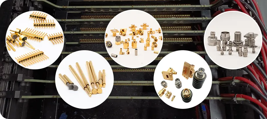

Choosing a reliable multipin feedthrough supplier demands attention to technical capability, quality certifications, customization flexibility, and after-sales support. The right supplier should demonstrate proven expertise in hermetic sealing technologies, maintain ISO and industry-specific certifications, offer transparent pricing with reasonable MOQs, and provide responsive engineering support throughout your project lifecycle. Successful procurement hinges on verifying supplier credentials through factory audits, reviewing case studies from similar applications, and confirming their ability to meet your exact specifications for pin count, materials, and environmental performance.
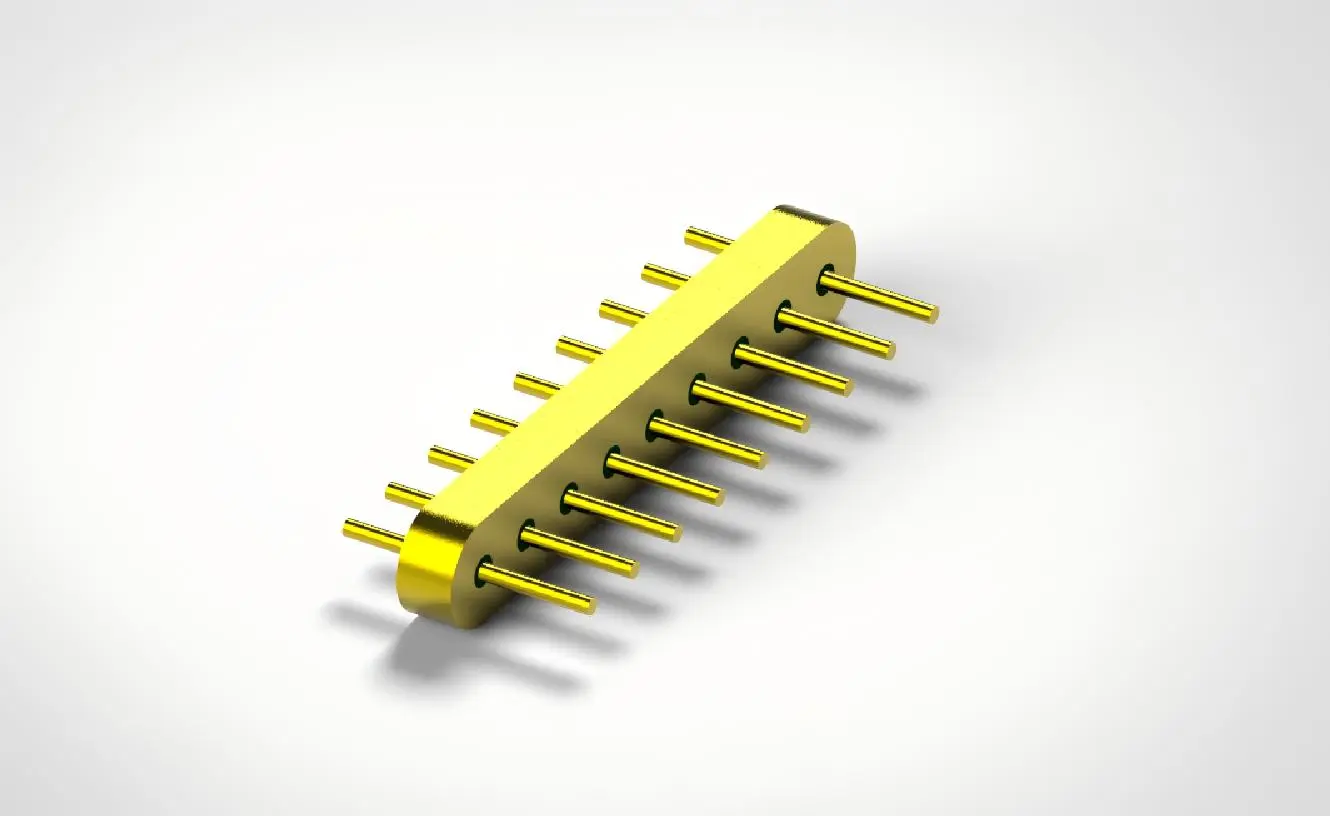
Core Criteria to Evaluate When Selecting a Multipin Feedthrough Supplier
To choose the best partner, you need to carefully look at a lot of factors that affect both the quality of the product and how quickly you can get it. The multipin feedthrough suppliers you hire should be able to show that they can do more than just make things.
Certifications and Compliance Standards
A supplier's process maturity and loyalty to standards can be objectively shown by quality certificates. ISO 9001 certification means that quality management systems have been in place for a while, while industry-specific certifications like MIL-DTL-83513 compliance and GJB 2446A approval show that the company can meet military-grade standards. Following the rules for RoHS and REACH ensures that companies are responsible for the environment and can enter markets in all regulatory areas. When looking at possible partners, you should ask for certification documents and check with the groups that issued them to make sure they are real.
Technical Capabilities and Product Range
A good supplier keeps a wide range of products with different pin numbers, sealing methods, and environmental grades. This breadth shows how flexible manufacturing is and how deep engineering goes. When you work with suppliers who offer both standard catalog items and custom designs, you can change your projects as needed. One supplier that can help with ceramic insulation, polymer sealing, and glass-to-metal sealing makes transportation and technical planning easier.
Customization Flexibility
Off-the-shelf options don't usually meet the specific needs of RF communications, photovoltaic tests, or medical device uses. Check out suppliers based on how many engineering resources they have set aside for customization. Can they change the pin shapes to fit the style of your PCB? Do they work with products or finishes that aren't standard? When it comes to custom feedthrough assemblies, suppliers with in-house design teams cut down on iteration cycles and speed up time-to-market.
Reputation and Client Feedback
A supplier's reputation is built by consistently meeting the needs of many customers and applications. Ask for case studies that show how deployments have worked well in businesses similar to yours. Customer reviews give you an idea of how quick, problem-solving, and reliable a business is over the long run. Because customers and regulators are so strict, manufacturing partners that work with the defense, medical device, and aircraft industries usually have higher quality standards.
Pricing Transparency and Total Cost Considerations
Clear price models help people trust each other and make planning easier. Competent providers give thorough quotes that include unit costs, tooling costs for special designs, and terms for shipping. Prices should be looked at in terms of the total cost of ownership, which includes things like dependability, warranty coverage, and the value of expert help. Minimum order quantities (MOQs) show how efficiently a product can be made. MOQs that are flexible allow for prototyping and small-batch production, while volume pricing rewards commitments that are bigger.
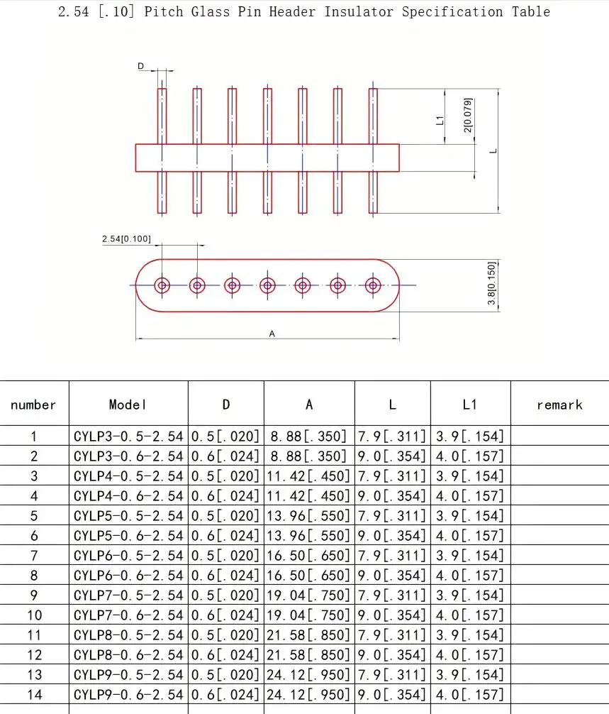
Comparative Analysis: Multipin Feedthrough Suppliers and Alternatives
When making strategic sourcing choices, it's helpful to know how the different feedthrough setups and multipin feedthrough supplier skills fit with the needs of your application.
Multipin vs. Single-Pin Feedthrough Performance
When compared to multiple single-pin units, multipin designs combine multiple electrical paths through a single penetration point. This means that the enclosure doesn't need to be changed as much, and installation is easier. This combination makes better use of room and often makes the whole system more reliable by reducing the number of possible leak paths. Single-pin feedthroughs, on the other hand, are better when different circuits need different voltage ratings, current capacities, or maintenance schedules. Cost analysis should look at both the prices of the parts and the labor needed to install them. Despite having higher per-unit prices, multipin solutions usually lower total installation costs.
Differentiating Supplier Capabilities
Leading manufacturers set themselves apart by introducing new technologies and strict quality controls. Some are great at working in ultrahigh vacuums with leak rates below 10⁻⁹ mbar·l/s, while others are great at working continuously at temperatures above 200°C. The efficiency of electromagnetic shielding changes a lot between suppliers, which makes it less suitable for RF uses. Customer service success shows up in how quickly technical support responds, how many samples are available, and how willing everyone is to work together to improve the design.
Benchmarking Tools and Validation Methods
Audits of suppliers let you see firsthand how things are made, how quality is controlled, and how well they can be tested. Factory visits show things about the technology of the tools, the level of cleanliness, and the skill level of the workers that written records alone can't show. Ask for proof testing of important factors such as leak rate verification, insulation resistance, and dielectric hold voltage. Suppliers who are sure of their quality will gladly let customers help with inspection procedures. Before committing to production quantities, testing a sample under your true working conditions gives you real-world information about how well it works.
Procurement Best Practices for Multipin Feedthroughs
Efficient buying methods help you get the right feedthroughs while staying within the project's budget and timeline and building good relationships with a multipin feedthrough supplier.
Technical Documentation Preparation
Details-rich specifications speed up accurate quotes and cut down on revision cycles. List the number of required pins, the maximum current per pin, the voltage that the device must be able to handle, and the temperature range it can work in. Give details about how you want the housing to be mounted, the material you want it to be made of, and any special weather hazards, such as salt spray, radiation, or chemical exposure. Include interface plans that show how the connectors fit together and PCB pad layouts for unique designs. During the review, it is important to make sure that everyone understands the acceptance standards for leak rates, insulation resistance, and contact resistance.
Managing Lead Times
Standard items from the store usually ship in two to four weeks. Custom multipin feedthrough designs, on the other hand, need eight to twelve weeks for molding, prototype testing, and production. Suppliers who have their own machine shops and can seal glass in-house usually have shorter lead times than those who outsource specialized processes. Make reasonable schedules that take into account sending goods internationally, clearing customs, and inspecting goods as they come in. Set up contact protocols for milestones to keep track of the work on custom orders and deal with problems before they happen.
International Trade Considerations
Cross-border purchasing adds a layer of complexity to the logistics process that needs careful attention to a number of factors. Make sure that your providers know the export control rules that apply to your business, especially those that have to do with defense and aircraft. Make Incoterms clear to figure out who pays for shipping, insurance, and clearing customs. Currency changes should be taken into account when setting prices for long-term supply agreements. Look for providers that have a history of sending goods internationally so that you can avoid delays and paperwork mistakes.
After-Sales Support Framework
Long-term partnerships with suppliers go beyond the initial delivery. Make it clear what the warranty covers when it comes to manufacturing flaws and early failures. Set up rules for how technical support should answer questions about installation, help with troubleshooting, and provide application engineering advice. When you need new parts quickly, responsive providers keep them in stock and offer faster shipping. When you do regular performance reviews, you can talk about quality trends, make sure that specs are clear, and look into ways to cut costs as production numbers rise.
Case Studies and Practical Tips for Choosing the Right Supplier
Real-life examples show how carefully choosing a multipin feedthrough supplier has a direct effect on the results of projects in a wide range of businesses.
Aerospace Application Success
A company that makes satellites needed multipin vacuum feedthroughs that could handle rapid changes in temperature and vibrations during launch. The supplier they chose gave them J30J series connectors with Kovar alloy housings, glass sintering technology, and qualification test data that showed the connectors met space-grade requirements. The feedthroughs stayed sealed after 500 thermal cycles at temperatures ranging from -55°C to +125°C and vibration tests at 196m/s². This relationship with a supplier provided steady performance over the course of a five-year mission, proving the value of strict supplier approval processes.
Medical Device Integration
A company that makes medical devices that are implanted needs special multipin feedthroughs made of safe materials and in small sizes. During the design phase, they worked together with their supplier partner to come up with pin configurations that kept signals safe while still fitting within size limits. The supplier's ISO 13485 certification and knowledge of FDA rules made the approval process go more quickly. After starting, reliability in the field was higher than 99.9% for three years, showing that supplier knowledge in specific uses lowers project risk.
Industrial Vacuum Equipment Deployment
A company that makes semiconductor equipment was looking for feedthroughs for chip processing rooms that worked at 10⁻⁵ Pa vacuum levels. They looked at a lot of sources by testing samples and inspecting factories before choosing one with special tools for finding helium leaks and written process controls. The transparent communication during custom design iterations and quick technical support during installation troubleshooting from the chosen supplier set the stage for ongoing collaboration across multiple product lines.
Procurement Manager Checklist
Successful supplier selection consistently addresses these decisive factors:
- Instead of depending only on what the seller says, check current certifications with the organizations that issued them.
- Read written case studies from apps that are similar to what you need.
- Talk to engineering staff, not just sales reps, to get a better idea of how customizable something is.
- Check how responsive technical support is by looking at how people talk to each other during the quote process.
- Make sure that testing equipment is available for the important parameters that are unique to your application.
- Make it clear how intellectual property rights are protected for custom designs that are worked on together.
- Before you place an order, make sure you have clear quality acceptance standards and inspection processes.
Conclusion
When looking for a trusted multipin feedthrough supplier, you need to think about their technical skills, quality processes, ability to make changes, and willingness to work with you. To make the best purchasing choices, you should carefully look at certifications, production capabilities, and past work that has been done in situations similar to yours. Factory surveys, sample testing, and checking references are all good ways to thoroughly evaluate suppliers. This lowers project risk and speeds up development times. Clear communication of requirements, quality standards, and performance standards sets the stage for long-term relationships that work well. As more and more industries need higher performance in tough conditions, your partnerships with suppliers become strategic assets that set your products apart and allow for new ideas.
FAQ
1. What certifications should I prioritize when evaluating potential suppliers?
Focus on ISO 9001 for quality management systems and certifications that are specific to your industry, like MIL-DTL-83513 for defense, ISO 13485 for medical devices, or AS9100 for aerospace. Environmental compliance through RoHS and REACH certification makes sure that rules are followed. For copies of current certificates, ask the organizations that issued them to confirm their validity from the multipin feedthrough suppliers.
2. What are typical lead times for custom multipin feedthrough orders?
For custom designs, the whole process usually takes eight to twelve weeks, which includes technical review, sample manufacturing, testing and validation, and production runs. Items from a normal catalog usually ship between two and four weeks. Lead times depend on the complexity of the design, the supply of materials, and the production plans of the suppliers. Set clear communication milestones to keep track of progress.
3. How extensively will suppliers support design modifications?
Capable providers give technical help throughout the design process by suggesting pin configurations, material choices, and mounting options. Partners who work together take part in design reviews, make suggestions for improving performance, and work with changes to specifications that happen during development. Check how responsive engineering was during the initial quote interactions to get an idea of the level of support.
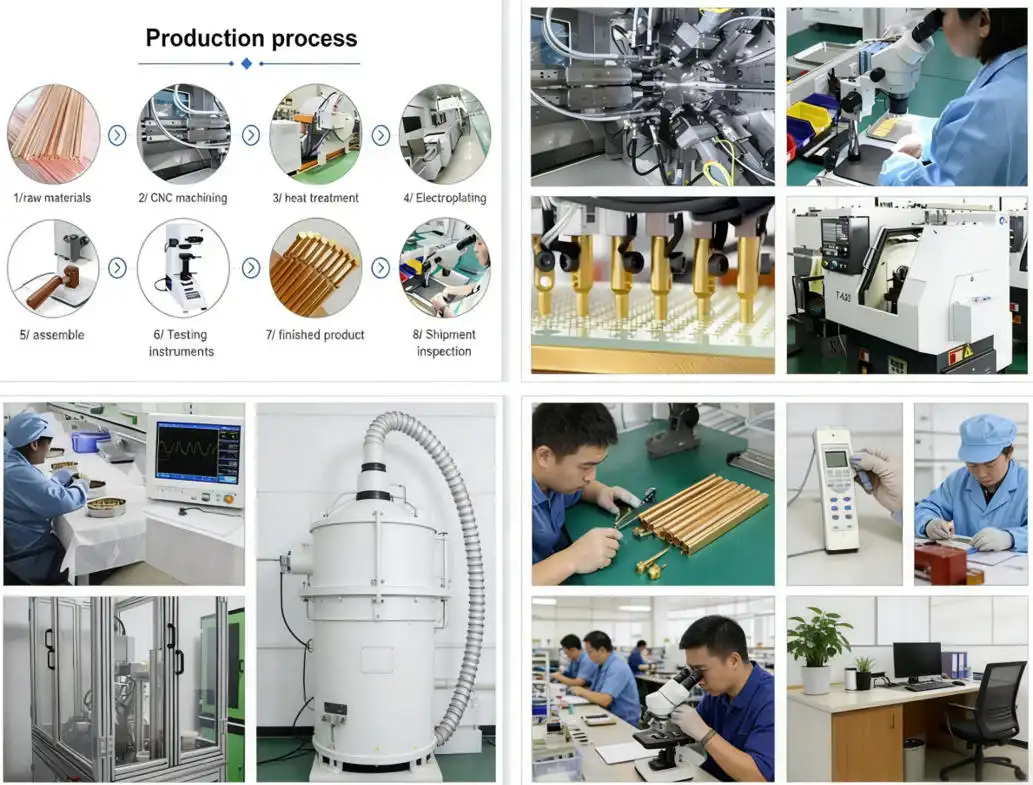
Partner with Chuangyu for Your Multipin Feedthrough Requirements
If you need precise electrical connectivity, Shaanxi Chuangyu Electronic Technology can help as a reliable multipin feedthrough supplier. They offer a wide range of multipin feedthrough solutions and have been in the engineering business for almost twenty years. Our factory in Xi'an makes unique designs, hermetically sealed connectors, and vacuum feedthroughs that meet the strict requirements of the semiconductor, medical device, photovoltaic, and aircraft industries. We keep our ISO quality certifications, our specialized glass sintering skills, and our engineering teams that know how to make solutions that fit the needs of each application. We are a strategic manufacturing partner for demanding applications because our prices are clear, our minimum order quantities (MOQs) start at prototype quantities, and our technical support is quick to respond throughout the lifecycle of your project. Email our engineering team at chuangyuwz01@cymicrowave.com to talk about your needs, ask for technical information, or set up a visit to our plant to see how we do quality control firsthand.
References
1. Electronic Industries Alliance. (2019). Standard for Hermetic Feedthrough Connectors: Design, Testing, and Quality Assurance. Arlington: EIA Publications.
2. Morrison, R., & Chen, L. (2021). Glass-to-Metal Sealing Technologies for High-Reliability Electronics. Boston: Technical Press International.
3. Institute of Electrical and Electronics Engineers. (2020). IEEE Guide for Selection and Application of Hermetic Electrical Feedthroughs. New York: IEEE Standards Association.
4. Defense Logistics Agency. (2018). MIL-DTL-83513: Detail Specification for Connectors, Electrical, Rectangular, Miniature, Hermetically Sealed. Philadelphia: DLA Document Services.
5. Wagner, H. J. (2022). Vacuum Technology for Industrial Applications: Component Selection and System Design. Berlin: Springer Technical Publishing.
6. National Aerospace Standards Committee. (2020). Quality Management Systems Requirements for Aviation, Space and Defense Organizations: AS9100D Standard. Washington: SAE International.
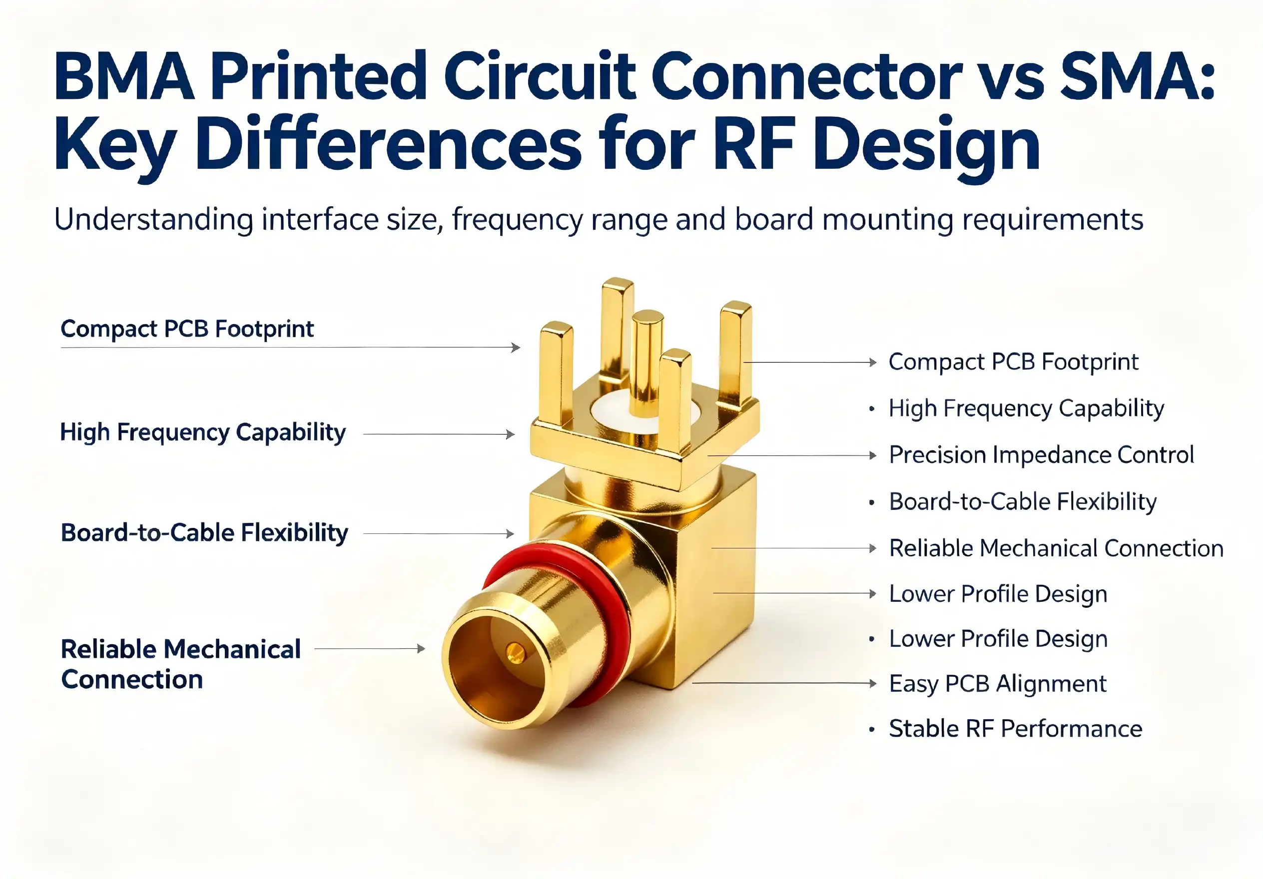
When designing RF systems for printed circuit boards, choosing between a BMA printed circuit connector and an SMA connector can dramatically affect your project's success. The BMA printed circuit connector offers a snap-on coupling mechanism designed for high-frequency stability and compact PCB footprints, typically supporting frequencies up to 28 GHz or higher. Meanwhile, SMA connectors utilize screw-type coupling for applications up to 18 GHz, providing robust mechanical durability. Understanding these distinctions helps engineering teams make informed decisions that balance performance, reliability, and procurement efficiency.
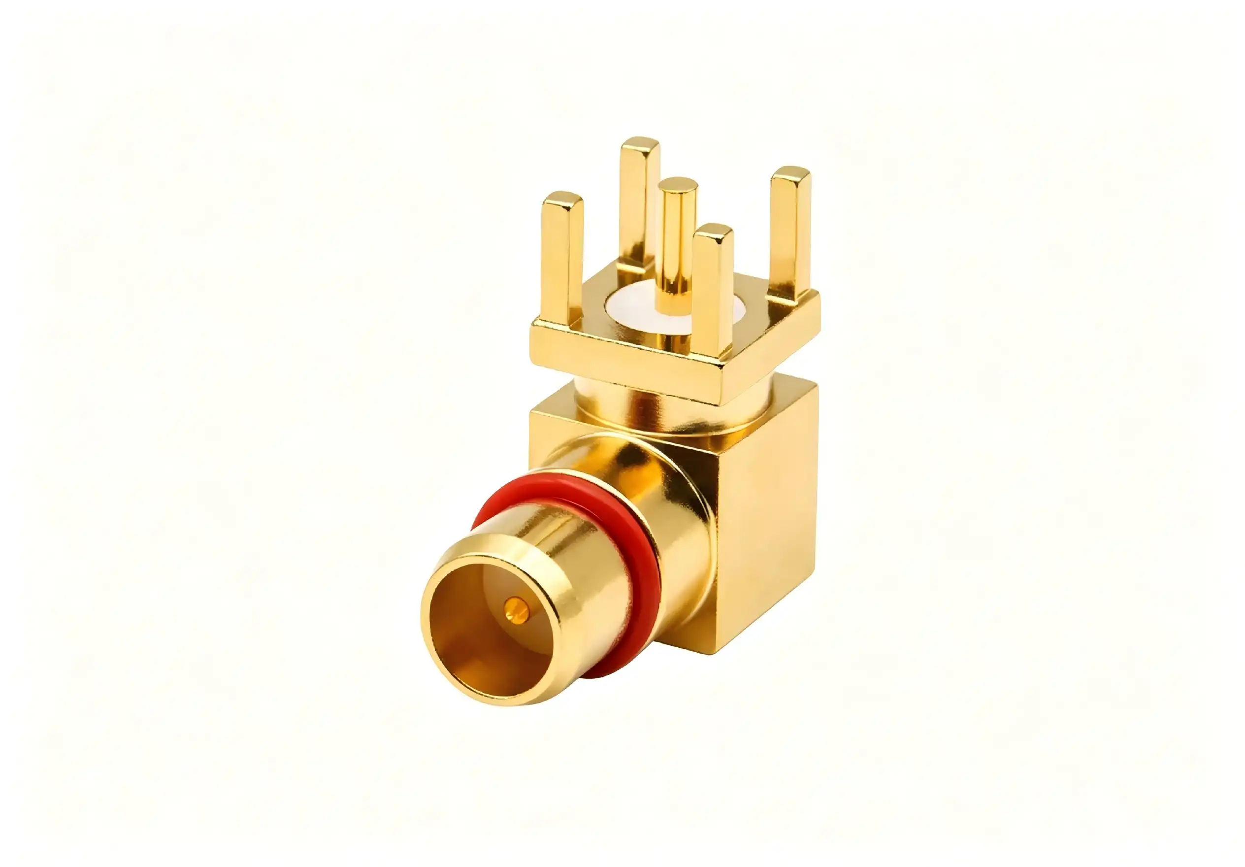
Key Technical Differences Between BMA and SMA Connectors
Electrical Performance Parameters
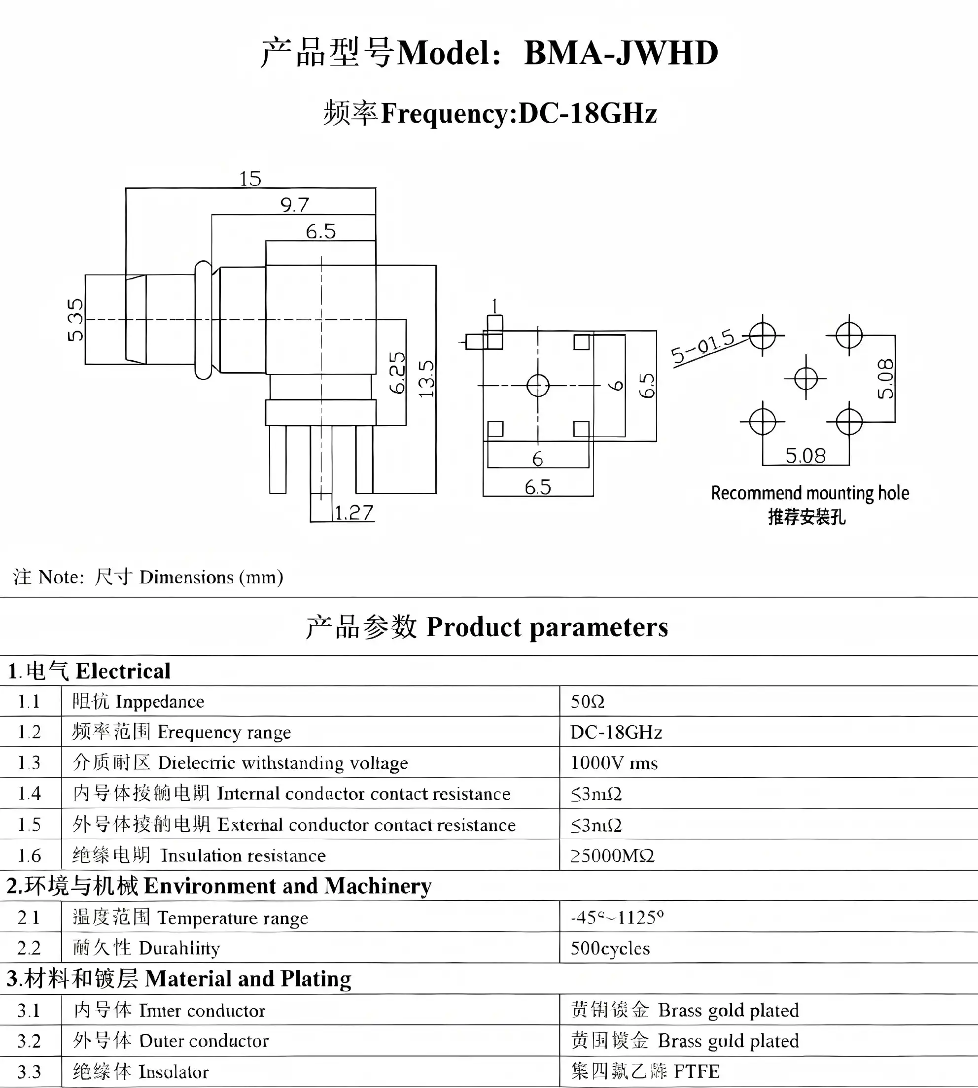
From an electronic point of view, the BMA printed circuit connector performs better in a number of important ways. The nominal impedance stays at 50 Ohms with a very small error range, and the voltage standing wave ratio stays below 1.15:1 at 18 GHz, getting better in high-performance versions. Insulation resistance is higher than 5000 MΩ, which ensures that there is little signal loss and stable performance over long periods of time.
At the frequencies they work at, SMA plugs also keep their 50-Ohm resistance and VSWR values usually below 1.20:1. Different types of connections have different insertion loss properties. BMA printed circuit connectors usually have lower loss at higher frequencies because their contact geometry is better and there are fewer coupling discontinuities. These differences in electricity have a direct effect on system-level performance metrics, changing everything from the signal-to-noise ratio to how well the signal is transmitted overall.
Mechanical Design and Mating Cycles
The technical design of these links affects how long they last, how easy they are to install, and how often they need to be maintained. BMA printed circuit connectors have a float feature that usually allows for 0.51mm of axial float and 0.20mm of radial float. This tolerance accommodation is very useful in blind-mate situations where exact alignment isn't possible, like in modular test equipment and aerospace systems with line replaceable units.
Through torque-controlled mating, SMA connectors offer reliable mechanical performance. They are usually rated for 500 mating cycles under normal conditions. When you enter or remove the threaded coupling, the mechanical stress is spread out evenly, which lowers the chance of touch damage. BMA printed circuit connectors have the same or higher mating cycle rates as other types, but they don't need rotational torque, which can put stress on PCB mounting points in places with a lot of shaking.
Material Selection and Durability
The materials used directly affect how long a connector lasts and how well it works in different environments. For maximum conductivity and corrosion resistance, BMA printed circuit connectors typically have gold-plated beryllium copper center contacts and stainless steel or passivated brass housings. These materials are made to strict military standards, such as MIL-STD-348 and MIL-PRF-39012. This means that products from different manufacturers can be used together and that they will work reliably in harsh conditions.
Similar material techniques are used in SMA connectors. Depending on cost and performance needs, gold or silver finishing can be used. Because SMA connectors have a bigger body, the housing can be built to be stronger. This makes the shielding and mechanical protection very good. When properly defined, both types of connectors can withstand high and low temperatures, humidity, and corrosive atmospheres. However, the BMA printed circuit connector's small size makes it better for uses that need to save weight, like satellite packages and robotic aerial vehicles.
Performance and Reliability in RF Systems
Signal Integrity Analysis
The BMA printed circuit connector always performs better in high-frequency situations when we look at signal integrity measures. When compared to standard SMA designs at frequencies above 20 GHz, test data from communication base stations and microwave link uses show better VSWR performance, less insertion loss, and less crosstalk. These gains come from better contact geometry, fewer breaks in the coupling, and tighter production tolerances.
These lab results have been confirmed by using radar systems and automatic test tools in the field. When engineers switch from SMA to BMA printed circuit connectors in millimeter-wave uses, they say the system is more sensitive, and there is less calibration drift. The snap-on coupling mechanism keeps the contact pressure constant, so threaded connectors don't have to worry about over-torquing or under-torquing.
Environmental Resilience
When designed and fitted correctly, both types of connectors are very resistant to shaking, changing temperatures, humidity, and corrosive environments. The spring-loaded contact design of the BMA printed circuit connector naturally absorbs shock, keeping the electricity flowing during high-G maneuvers in aircraft and transportation vibrations in mobile communication systems.
The BMA printed circuit connector works well in harsh conditions, which is why it is used in military and defense applications. Temperature changes from -55°C to +125°C don't affect the electrical performance of satellite communication systems, navigation systems, or radar installations for the whole time they are in use. Getting rid of threaded unions lowers the chance of thread damage, seizing, and galling that can happen in tough settings where mating cycles happen over and over again.
Long-Term Reliability Metrics
Accelerated life tests and field failure analysis data show that BMA printed circuit connectors keep their electrical specs for a long time with little change. The lack of moving parts during mating keeps the connector and PCB mounting structure from wearing out, which improves the general stability of the system. This feature is particularly useful in places where repair is hard to get to or costs a lot, like on military equipment that is in action or faraway communication infrastructure.
Procurement Considerations for B2B Buyers
Cost Analysis and Total Ownership Value
Budgets and how much something costs are big factors in a lot of buying choices, which need more careful thot than just the initial unit price. Because they are widely used, have mature supply lines, and can be made in large quantities, SMA connectors usually have lower unit costs. These products are cheaper, which makes them appealing for uses where their technical specs meet design needs.
Due to their specialized manufacturing processes, tighter tolerances, and advanced materials, BMA printed circuit connectors are more expensive. Instead of just looking at the prices of parts, procurement managers should look at the total cost of ownership. Over the lifecycle of a product, factors like snap-on coupling that cuts down on assembly time, lower failure rates in high-vibration environments, and better system performance can make up for higher initial costs.
Supply Chain Strategy and Vendor Selection
To make supply chains that are strong, you need to carefully evaluate your suppliers and build strategic relationships with them. Leading companies like Murata, Amphenol, Pasternack, and TE Connectivity make both BMA and SMA connectors, and they have different lead times, minimum order quantities, and ways to make the connectors your own. We at Chuangyu are experts in making precise BMA printed circuit connectors and RF cable assemblies. We offer full support from the initial design consultation all the way through mass production.
When looking for important RF parts, you should pay close attention to supplier approvals. Check to see if possible sellers follow ISO 9001 quality management systems, meet military requirements, and take strict steps to stop counterfeiting. Concerns about the authenticity of components affect both types of connections, but BMA printed circuit connectors are more likely to be faked because they are more valuable.
Lead Time Management and Inventory Planning
Standard SMA connectors are easy to find and usually ship from stock with short lead times. It could take 6 to 8 weeks to make and send custom SMA setups. Lead times for BMA printed circuit connectors are typically longer, especially for specialized versions or custom configurations. They can be anywhere from 8 to 12 weeks, depending on how complicated the order is and how many are being placed.
Lead time problems can be lessened by planning your inventory strategically. During the design process, procurement managers should work closely with engineering teams to predict what will be needed. This should be done with enough time for vendors to be qualified, samples to be evaluated, and initial storage orders to be placed. Our Xi'an facility keeps a ready supply of common BMA printed circuit connector configurations, which lets qualified customers get their orders faster.
Making the Right Choice: BMA vs SMA for Your RF Design
Application-Specific Selection Criteria
To choose the best connector, you need to match its technical skills to the needs of your program. The BMA printed circuit connector is the best choice for high-frequency uses above 20 GHz, PCB layouts with limited space, automated or robotic assembly processes, blind-mate setups, and places where shaking or shock is common. This is why BMA technology is perfect for phased array radar modules, semiconductor automated test equipment, aerospace line replaceable units, and the next generation of wireless networks.
SMA connections are still the best choice for uses up to 18 GHz where mechanical robustness is more important than space limits, threaded coupling gives the necessary retention force, cost is the most important factor in design decisions, and standard SMA interfaces are needed for compatibility with older systems. SMA has been widely used and proven to be reliable, which makes it useful for traditional test equipment, general-purpose RF instrumentation, antenna connections, and cost-effective communication systems.
Future-Proofing Design Decisions
Industry trends show that BMA technology is being used more and more as RF systems move toward higher frequencies and more integration density. As the phone industry moves from 4G to 5G and then to 6G networks, there is a greater need for ports that can handle millimeter-wave bands with little signal loss. When choosing connector systems, design teams should think about not only what they need right now, but also what they might need in the future, like updates or new products in the line.
Because BMA printed circuit connectors are modular, they make it easier for designs to change and for new technologies to be added. When compared to designs that focus on threaded connectors, systems built around BMA interfaces are better able to handle performance upgrades, component swaps, and changes to the configuration. This adaptability is a great way to protect against becoming obsolete in market areas that change quickly.
Balancing Technical and Commercial Factors
When choosing connectors, it's important to find a balance between technical performance needs and business realities like budgets, supply chain capabilities, and how much risk an organization is willing to take. Instead of optimizing each metric on its own, engineering teams should work closely with buying professionals to look at trade-offs as a whole.
When adding BMA printed circuit connectors to existing product lines, risk mitigation strategies should be thot about. Using parallel qualification programs, phased execution plans, and keeping the ability to use two sources can lower the risks of change while still improving performance. During this transition period, our technology team offers full support, including application engineering help, sample supply, and production qualification testing.
Conclusion
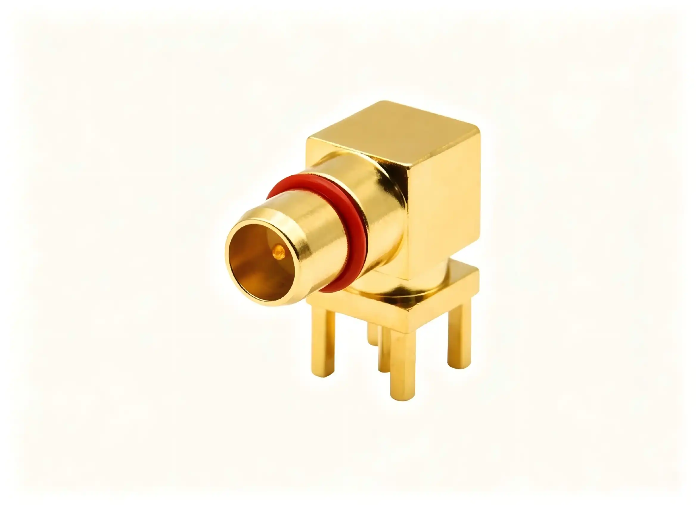
Matching connector power to particular application needs is the primary factor in choosing between BMA printed circuit connectors and SMA connectors. BMA printed circuit connectors work better in high-frequency, space-limited, and vibration-prone settings because they have a snap-on coupling device, a small footprint, and better electrical properties. SMA connectors are still useful in situations where their threaded coupling, long history of dependability, and low cost are important to the design. When making selection choices, procurement and engineering teams should look at technical specs, total cost of ownership, supply chain issues, and the need to make sure the system will work in the future. By knowing about these differences between connectors, you can make decisions that improve the speed, reliability, and business success.
FAQ
1. Can BMA and SMA connectors be used interchangeably on the same PCB?
They are not directly interchangeable because they are physically and mechanically different. BMA printed circuit connectors and SMA connectors are not interchangeable. The BMA has a slide-on interface with contacts that are held in place by springs, and the SMA uses a threaded coupling. There are adapter options for test and measurement situations where temporary BMA-to-SMA links are needed. However, these adapters add extra insertion loss and VSWR degradation, which could make the system less effective in real-world settings.
2. What frequency range advantage does the BMA printed circuit connector offer?
BMA printed circuit connectors can usually handle frequencies up to 28 GHz while still keeping the signal strong. Some special versions can even work above 40 GHz. Standard SMA links work well up to 18 GHz, and precision versions can work up to 26 GHz. Because it works better at higher frequencies, BMA technology is needed for millimeter-wave uses like 5G infrastructure, advanced radar systems, and high-speed data transfer networks. This is because signal integrity at high frequencies has a direct effect on how well the system works.
3. How does the snap-on mechanism benefit high-density PCB layouts?
Because BMA printed circuit connectors have a snap-on coupling system, you don't need to leave any room for a wrench or your fingers to fix them, as you do with threaded SMA connectors. Because of this, designers can put connectors closer together, making the most connections possible on boards with limited space. The ability to blind-mate with axial and radial float tolerance accommodation makes mating safe in modular systems where perfect alignment is not possible. This lowers the complexity of assembly and raises the manufacturing yield.

Connect with Chuangyu for Your BMA Printed Circuit Connector Solutions
Picking the right RF adapter provider is just as important to the success of your project as the technical details themselves. Chuangyu is a top company that makes BMA printed circuit connectors. They offer precision-engineered solutions that meet the strict needs of aerospace, defense, telecommunications, and semiconductor testing. Our factory in Xi'an's Chang'an Innovation Technology Industrial Park follows strict quality standards and can make more than 500,000 RF components every year. It also has full testing facilities to make sure that every BMA printed circuit connector meets your exact needs.
Whether you need standard setups or custom, non-standard solutions, our engineering team can help you with everything, from the first design meeting to mass production. For full datasheets, technical specs, and sample evaluations, please email us at chuangyuwz01@cymicrowave.com. This is for procurement managers, R&D engineers, and technical directors. These products are made to last and work well.
References
1. Johnson, R. T., & Williams, P. A. (2021). "High-Frequency Connector Technology for Next-Generation Wireless Systems." IEEE Transactions on Microwave Theory and Techniques, 69(4), 2156-2168.
2. Chen, L., Martinez, J. & Goldstein, M. (2020). "Comparative Analysis of RF Connector Performance in Harsh Environments." Journal of Electronic Materials, 49(7), 4321-4335.
3. National Institute of Standards and Technology (2022). "RF and Microwave Connector Measurement Standards: Guidelines for Test Engineers." NIST Special Publication 1900-201.
4. Anderson, K. E. & Thompson, D. R. (2019). "Blind-Mate Connector Systems for Phased Array Radar Applications." International Journal of RF and Microwave Computer-Aided Engineering, 29(8), e21847.
5. Defense Logistics Agency (2021). "MIL-STD-348C: Radio Frequency Connector Interfaces - General Requirements for." Department of Defense Interface Standard.
6. Zhang, W., Kumar, S. & Peterson, B. (2023). "Signal Integrity Analysis of High-Density PCB Interconnects at Millimeter-Wave Frequencies." IEEE Transactions on Components, Packaging and Manufacturing Technology, 13(2), 234-247.
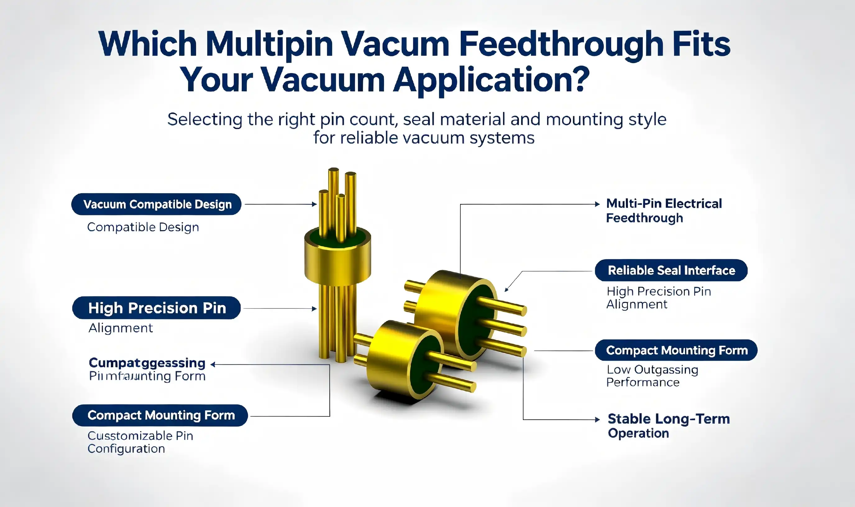
Selecting the appropriate multipin vacuum feedthrough depends on understanding your specific vacuum environment requirements, electrical specifications, and operational constraints. A hermetic multipin feedthrough that balances pin density, current capacity, seal integrity, and material compatibility will ensure long-term reliability in semiconductor processing, aerospace systems, or medical device applications. Matching pin count configurations with your signal transmission needs while verifying leak rates and temperature tolerance creates the foundation for successful vacuum system integration.
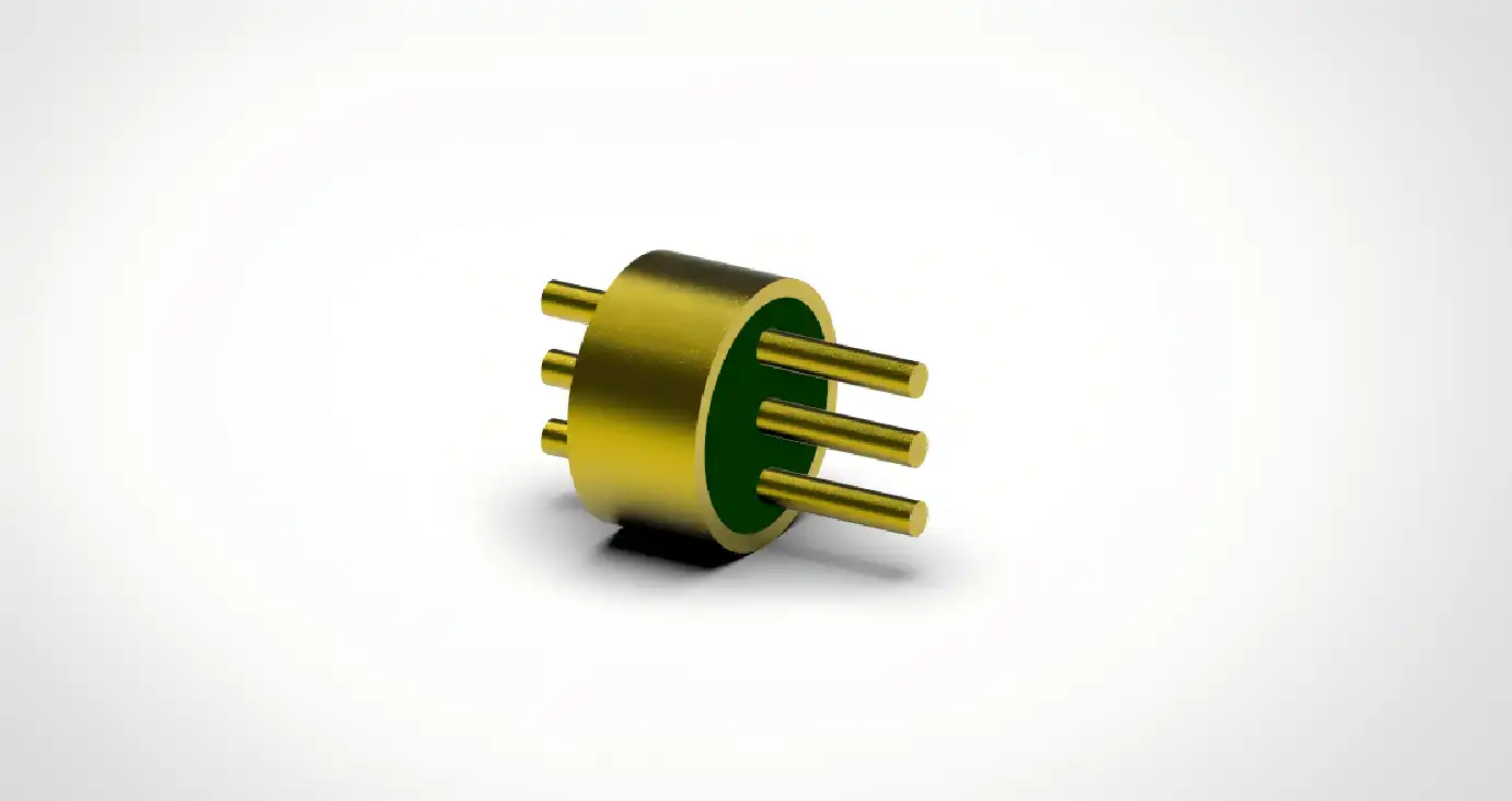
Understanding Multipin Vacuum Feedthroughs: Functionality and Key Specifications
What Makes Multipin Vacuum Feedthroughs Essential?
Multipin vacuum feedthroughs are a special kind of electrical connector that can send more than one signal through vacuum barriers while keeping the environment separate. These parts connect the atmosphere to the vacuum environment so that equipment can work without affecting the vacuum's integrity. The main benefit is that it combines many electrical paths into a single, small interface, which makes installation easier than using multiple single-pin options.
As a basic building block, conductor pins go through an insulating material, which is usually glass or ceramic, and are attached to a metal frame. This system makes a seal that keeps air out, so gas molecules can't move from one setting to another. Leak rates in glass sintering can be as low as 1.01325×10⁻³ Pa·cm³/s, which meets strict requirements for ultra-high vacuum applications where pressures are 10⁻⁵ Pa or lower.
Critical Specifications That Define Performance
When looking at different hermetic feedthrough choices, a number of technical factors directly affect which ones will work best. There are a lot of different pin count designs, from small 9-pin sets to high-density 100-pin units. The pitch spacing can be as small as 1.27mm, which lets a lot of signals fit into small mounting areas. The ability to transmit power is based on its electrical rating. Standard designs can handle 3A per contact, while high-current versions can handle up to 13A.
Tolerance for high or low temperatures is very important in harsh environments. Multipin feedthroughs that are standard work reliably from -55°C to +125°C. Some more advanced models can even handle short exposure to 260°C during reflow soldering. Insulation resistance greater than 5000 MΩ protects the integrity of the signal, and dielectric withstand voltage values of 800V keep the electricity from breaking down when the system is under a lot of stress. Contact resistance below 10 mΩ keeps power loss and heat generation to a minimum across twisted rubber contact pins that have seven contact points each.
Material Selection and Vacuum Compatibility
Material science is the main thing that determines how long and reliably a feedthrough works. Kovar metal housings and glass insulators have the same thermal expansion rates, which keeps the seal from breaking when the temperature changes. Surface treatments improve performance. For example, gold plating is better at resisting rust and conducting electricity, and special nickel carbon fluoride composite coats can handle being exposed to salt spray for more than 500 hours.
Glass insulation materials are very good at keeping out vacuums and electricity, and they keep their hermetic integrity over long periods of time. Ceramic options can handle higher temperatures and have higher material strength for uses that involve shock or shaking. When electromagnetic shielding works at 85dB or higher, it keeps outside noise from interfering with sensitive signals. This is especially important in RF and microwave communication situations where signal clarity directly affects measurement accuracy.
Comparing Multipin Vacuum Feedthrough Options for Your Needs
Multipin vs. Single-Pin Feedthrough Solutions
Depending on the needs of the system architecture, consolidated multipin designs or distributed single-pin installations are the best choice. When compared to equivalent single-pin arrays, multipin vacuum feedthrough assemblies take up 60–70% less mounting space, making chamber wall integration easier. The amount of work needed to install something goes down by the same amount. One 37-pin feedthrough replaces dozens of separate holes, which cuts down on installation time and possible leak points.
But single-pin designs are more flexible for systems that need to put pins in a certain way or expand in stages. When circuits are physically separated, it's easier to figure out what's wrong. Single-pin modularity makes it easier to adapt to changing needs, which is helpful for prototype development or research applications. Multipin consolidation is very helpful for production systems with clear, stable configurations because it lowers the costs of installation and the difficulty of long-term maintenance.
Glass vs. Ceramic Insulation Properties
Glass sintering bonds wires and housing materials at the molecular level, making airtight seals that are very resistant to leaks. This way of making things is most common in high-reliability uses like medical and spacecraft parts, where vacuum integrity has a direct effect on mission success or patient safety. Insulators made of glass work well in mild temperature ranges and keep their electrical features for decades.
Ceramic barriers work great in places with very high temperatures and in situations where strength is important. The material can handle higher shock and vibration loads without affecting the integrity of the seal. This is very important for space launch vehicles or industrial automation equipment that has to deal with repeated mechanical stress. Ceramic feedthroughs usually cost more than glass ones, but this is only necessary when the conditions of the application are too tough for glass or when longer durability lowers the total cost of ownership.
Seal Technology Performance Comparison
Long-term dependability under operational stress is based on the vacuum seal methodology. For ultra-high vacuum uses, glass-to-metal seals are the best. They can achieve leak rates below 10⁻⁹ mbar·L/s, which can be proven by helium mass spectrometer tests. During the sintering process, metallurgical bonds are formed that can't be broken by temperature cycles or mechanical shaking.
Rubber sealing methods work well in mild vacuum situations where working pressures stay above 10⁻³ Pa, and glass sintering choices are limited by cost. Elastomer seals need to be inspected and replaced on a regular basis—usually every three to five years, depending on how they are exposed to the environment. This adds a level of maintenance that isn't needed for glass-sealed designs. Combining metal, ceramic, and polymer elements in hybrid approaches improves certain performance parameters while keeping cost, temperature tolerance, and leak rate needs in mind for specific industrial uses.
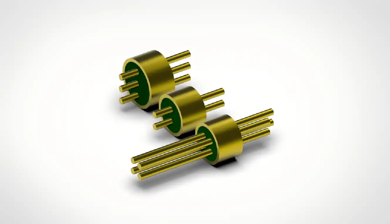
How to Choose the Right Multipin Vacuum Feedthrough for Your Application
Defining Your Vacuum System Requirements
A thorough description of requirements is the first step to successful multipin vacuum feedthrough selection. Write down the vacuum pressure levels that your system keeps up. For example, processing semiconductor wafers needs an ultra-high vacuum level below 10⁻⁷ Pa, while vacuum coating works well at 10⁻³ Pa. Voltage ranges, current loads per circuit, and signal types like DC power, low-frequency control signals, or high-frequency RF transfer must all be included in electrical specs.
Environmental conditions affect the choice of material and seal. Extremes in operating temperature, exposure to corrosive atmospheres, levels of mechanical vibration, and sources of electromagnetic interference can all affect the right configurations. Pin count requirements balance the need for connections now with the possibility of growth in the future. Physical mounting limits determine the form factors that can be used and how well they work with flanges.
Evaluating Critical Selection Criteria
Mechanical robustness is important for installations that are under a lot of physical stress. In order to meet installation torque requirements, feedthrough housings must not deform the seal and must also be able to withstand differential pressure loads without losing their structural integrity. In aerospace and automotive testing environments, where resonant frequencies can cause contact wear or seal fatigue over time, vibration resistance is very important.
The cost of an item isn't the only thing that is looked at when analyzing costs; installation work, testing needs, and lifecycle upkeep are also taken into account. Standard catalog products are available right away and have reasonable prices for common configurations. Custom designs are good for meeting specific needs, but they come with engineering lead times of 4 to 8 weeks and minimum order amounts that can hurt project budgets. When judging a supplier, you should look at how well they follow certifications like RoHS, ISO quality management systems, and approvals specific to your industry, such as MIL-DTL-83513 for defense uses.
Balancing Standard and Custom Solutions
Off-the-shelf multipin feedthroughs work for about 70% of industrial vacuum uses because they have standard pin numbers, flange sizes, and electrical ratings. These catalog items are made using tried-and-true methods that guarantee stable quality and faster delivery times—usually two to three weeks for standard setups and six to ten weeks for custom designs.
When application needs are very different from existing standards, custom feedthrough development becomes a realistic business option. Custom engineering is worth the money when there are non-standard pin layouts, special materials that work well with chemicals, built-in filtering parts, or unique mounting interfaces. Tooling amortization over multiple orders can be negotiated in high-volume production environments, which lowers the cost per unit for long-term procurement relationships. When you involve suppliers early on in the design process, you can work together to improve the final product by changing the specifications to make the best use of existing manufacturing capabilities while still meeting performance goals.
Practical Applications and Benefits of Multipin Vacuum Feedthroughs
Semiconductor Manufacturing Integration
A lot of the electrical connections in deposition chambers, etching systems, and wafer inspection tools depend on hermetic multipin vacuum feedthroughs for semiconductor processing equipment. These systems make it possible to send power, control signals, and sensor data all at the same time. They also keep the ultra-high vacuum conditions that are needed to make features on the nanometer scale. A standard plasma deposition chamber has several 37-pin or 61-pin feedthroughs for delivering RF power, measuring temperature, controlling gas flow, and automating handling systems.
The high-density integration cuts down on chamber wall penetrations, which makes upkeep easier and lowers the number of possible ways for contamination to get in. When facilities that process 300mm wafers switch from distributed single-pin installations to consolidated multipin architectures, their uptime goes up a lot. Using helium mass spectrometry to check the leak rate before starting up the chamber protects the vacuum, which keeps production from being held up or contaminated, which could cost a lot of money and lower chip yields.
Aerospace and Defense Applications
Multipin vacuum feedthroughs are needed for electrical links to go through spacecraft pressure tanks and sensor housings. These parts can handle launch vibration loads of more than 196 m/s² and keep their hermetic seals even when they are exposed to temperature changes caused by handling cryogenic propellants or the sun's rays. Satellite position control systems use high-reliability feedthroughs that meet GJB 2446A military standards. This makes sure that missions are successful for many years.
Defense applications like radars and platforms for guiding missiles need feedthroughs that work with MDM series military standards. This lets different platforms work together and find qualified suppliers. When you combine electromagnetic shielding with mechanical strength and proven hermetic performance, you get key defense infrastructure that can't fail and has effects that go beyond the cost of replacing equipment.
Medical Device and Industrial Automation
Implantable medical devices, like pacemakers, use tiny sealed feedthroughs to send electrical data through titanium housings without letting body fluids in. Biocompatibility rules require certain materials and surface treatments, and decades of continued use are used to measure long-term dependability. Larger multipin configurations are used for motor control, sensor feedback, and power distribution in sterilizable enclosures for external medical equipment like diagnostic imaging systems and surgical robots.
Industrial automation settings like vacuum coating machines, heat treatment ovens, and scientific instruments can benefit from multipin designs because they save room and are easy to install. When compared to similar single-pin arrays, production facilities report 30–40% less installation work, which speeds up equipment commissioning plans and cuts down on downtime during maintenance cycles.
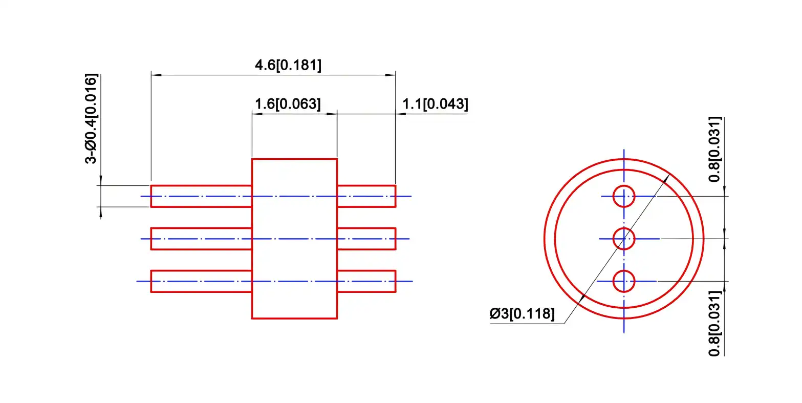
Procurement Insights: Where and How to Buy Multipin Vacuum Feedthroughs
Identifying Qualified Manufacturers and Suppliers
To find high-quality hermetic multipin vacuum feedthroughs, you need to find manufacturers who have a track record of being good at both precision machining and glass-to-metal sealing technology. Suppliers that have been around for a while keep full product lines that include both standard catalog items and custom engineering services. Verification of quality management standards, such as ISO 9001 and approvals relevant to the industry, gives customers trust in the stability and tracking of the production process.
Superior suppliers are different from commodity vendors because they can provide technical support. Having access to resources for applications engineering helps choose the best feedthrough for each vacuum system, avoiding mistakes or poor performance that could cost a lot of money. Suppliers who offer design collaboration during the development stages of a product can help with making the product easier to make, lowering costs, and making sure it works well.
Understanding Pricing Structures and Lead Times
Pin count, material, sealing technology, and amount of customization all have a significant impact on the price of multipin vacuum feedthroughs. Standard catalog items with glass-sealed Kovar housings usually have prices that range from average to high-end, based on the number of pins and the electrical values. Engineering fees and tooling costs must be spread out over multiple orders for custom designs that use special materials, non-standard pin layouts, or combined components.
Lead times should take into account how complicated the manufacturing process is. Standard goods are shipped in two to four weeks, but unique designs take six to ten weeks, which includes technical validation, making the tools, and testing the first product. Orders of more than 100 units may cause schedules to slip, but they can also lead to price cuts of 15 to 30 percent, based on how complicated the setup is and how well the production run goes.
Ensuring Compliance and Technical Documentation
Documentation showing that the equipment is compliant with RoHS is needed to sell it in Europe or to companies that have green buying policies. Suppliers should give you information on the materials they use and papers that show they follow the rules about dangerous substances. Full datasheets with electrical specs, mechanical models, leak rate performance, and suggested installation steps help people make smart decisions and make it easier to connect systems.
Before agreeing to production numbers, performance claims can be checked by asking for sample units to be evaluated. As part of the testing process, the leak rate should be checked with helium mass spectrometry, the contact resistance should be measured, and the insulation resistance should be checked under stress conditions that match the needs of the application. Setting up clear lines of communication with supplier technical teams and being specific about your questions, such as the level of vacuum pressure, electrical needs, environmental conditions, and expected quantities, speeds up the quotation process and makes sure that the solutions being offered meet the needs of the application.
Conclusion
To choose the best multipin vacuum feedthrough, you have to weigh the technical specs against the limitations of your application and your budget. To make smart decisions, you need to know about pin density requirements, seal technology options, material compatibility, and environmental conditions. If you need ultra-high vacuum integrity for semiconductor processing, mechanical strength for aircraft systems, or biocompatibility for medical devices, choosing the right feedthrough has a direct effect on how well your system works and how reliable it is. Engaging qualified suppliers early in the design process, trying samples to confirm performance, and setting clear standard requirements all make buying easier while lowering integration risks and ensuring long-term vacuum system performance.
FAQ
1. What leak rate should I specify for my vacuum application?
How fast a leak has to happen depends on the gas pressure and how sensitive the machine is. For ultra-high vacuum applications below 10⁻⁷ Pa, leak rates must be less than 10⁻⁹ mbar·L/s. This can be done with glass-sealed multipin feedthroughs and helium mass spectrometer verification. Industrial vacuum coating systems that work at 10⁻³ Pa can handle leak rates of about 10⁻⁶ mbar·L/s. Finding the right feedthrough standards is easier when you talk to vacuum system makers about the total amount of leakage that is allowed.
2. Can multipin feedthroughs handle RF signals?
Specialized hermetic feedthroughs made for RF transmission have 50Ω impedance matching and keep voltage standing wave ratios below 1.2, which means they can handle frequencies up to the millimeter-wave range. In standard multipin configurations, pin density is more important than RF performance, and signals may get weaker at higher frequencies. When asking for quotes, be very clear about the RF frequency ranges and resistance needs to make sure that the suggested solutions meet your signal integrity goals.
3. How do I prevent seal damage during installation?
Seal harm can be avoided by following the manufacturer's fitting instructions. For glass not to crack, reflow welding temps must stay below 250°C. It is very important to follow the torque specs for mounting hardware exactly, because too much tightening causes mechanical stress that breaks down the seal. Helium leak testing before installation checks the state of the seal before it is integrated, and testing after installation makes sure that the vacuum integrity is maintained during the mounting process.
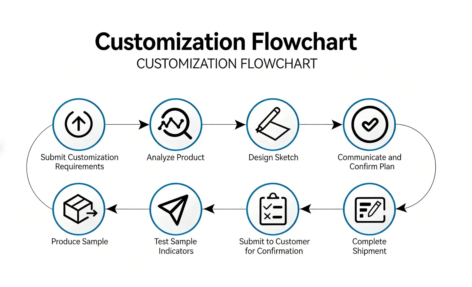
Partner with Chuangyu for Reliable Multipin Vacuum Feedthrough Solutions
Shaanxi Chuangyu Electronic Technology makes high-quality hermetic connectors and multipin vacuum feedthrough systems for semiconductor, military, medical, and industrial automation uses that are very specific. We make sure that every part meets strict quality standards by using our knowledge of glass-to-metal sealing technology and our wide range of testing tools, such as helium mass spectrometry leak detection. As a well-known multipin vacuum feedthrough seller, we work with top photovoltaic companies and RF communication providers. We offer both catalog goods and custom-engineered solutions, and our lead times are flexible to fit your project plans. Email our applications engineering team at chuangyuwz01@cymicrowave.com to talk about your vacuum system needs, get technical datasheets, or set up an evaluation sample.
References
1. Roth, A. (2012). Vacuum Sealing Techniques. Springer Science & Business Media, highlighting glass-to-metal seal methodologies and leak rate testing protocols.
2. O'Hanlon, J.F. (2003). A User's Guide to Vacuum Technology, 3rd Edition. John Wiley & Sons, detailing feedthrough selection criteria for industrial vacuum systems.
3. Hablanian, M.H. (1997). High-Vacuum Technology: A Practical Guide, 2nd Edition. Marcel Dekker, covering hermetic connector applications in semiconductor manufacturing.
4. Harris, N.S. (2008). Modern Vacuum Practice, 3rd Edition. BOC Edwards, examining electrical feedthrough integration in ultra-high vacuum environments.
5. Chambers, A., Fitch, R.K., & Halliday, B.S. (1998). Basic Vacuum Technology, 2nd Edition. CRC Press, discussing seal material selection and vacuum compatibility.
6. Wutz, M., Adam, H., & Walcher, W. (1989). Theory and Practice of Vacuum Technology. Vieweg+Teubner Verlag, analyzing multipin feedthrough performance in aerospace applications.
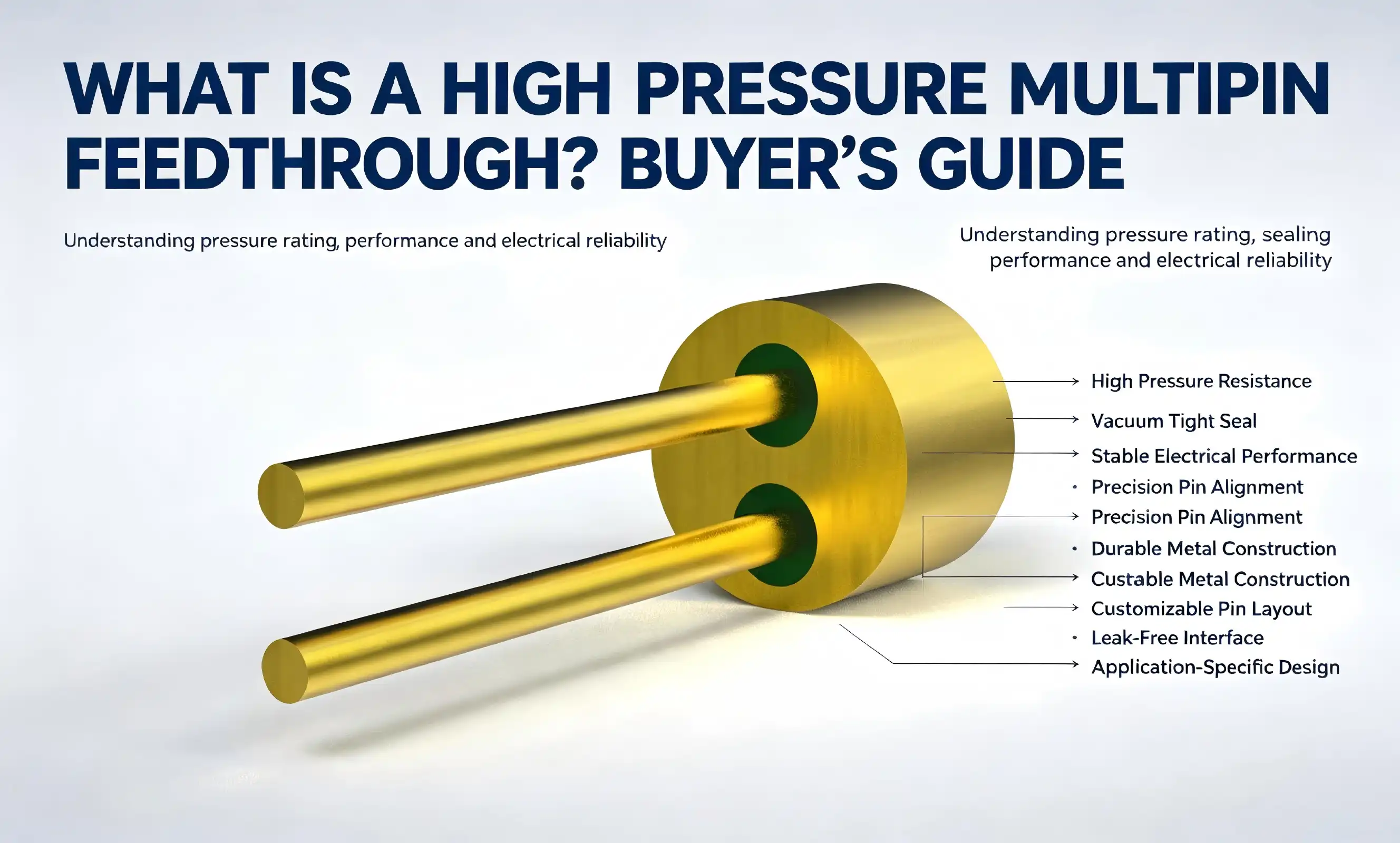
A high-pressure multipin feedthrough is a specialized electrical connector engineered to transmit multiple electrical signals simultaneously through pressure barriers while maintaining hermetic sealing integrity. These components enable safe electrical connections across environments experiencing extreme pressure differentials, ranging from vacuum chambers to high-pressure vessels. Unlike standard connectors, these feedthroughs combine dense pin configurations with robust sealing technologies—typically glass-to-metal or ceramic-to-metal bonds—ensuring zero leakage even under demanding conditions. Their construction incorporates insulating materials that provide electrical isolation while withstanding pressures exceeding 10,000 psi, making high pressure multipin feedthrough indispensable for industries like aerospace, semiconductor manufacturing, and oil and gas exploration.
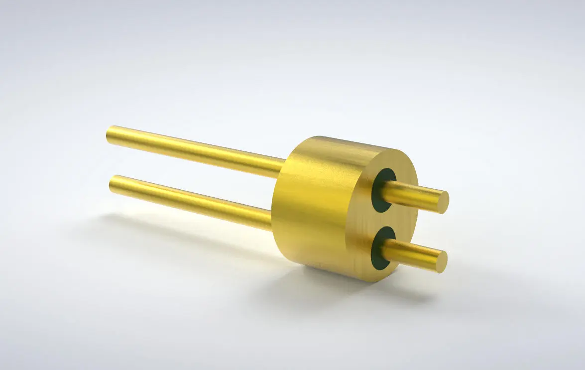
Comparison and Selection Criteria for High Pressure Multipin Feedthroughs
Performance Differences: Multipin Versus Single-Pin Solutions
Which one to use—multipin or single pin—depends on the needs of the system architecture. Single-pin designs are easy to use and can handle the highest pressures. The individual seals reduce the risk of cross-contamination. But they take up a lot of space on the panel and make the total leak path more vulnerable when more than one connection is needed.
Multipin configurations group connections together, which cuts down on installation time and panel holes. A single 37-pin high-pressure multipin feedthrough can replace dozens of separate parts, which lowers the general rate of system leakage and makes upkeep easier. In exchange, the per-pin current capacity is a little smaller, and tailoring is more difficult.
Sealing Technology Analysis: Glass Versus Ceramic
Glass-to-metal sealing is most common in situations where temperatures and pressures are moderate. This method is used in the J30J line, which has sintered glass that joins molecularly with Kovar housings. This method achieves high hermeticity at lower production costs, which makes it perfect for medical devices and lab equipment.
In harsh environments, ceramic-to-metal sealing works better than other methods. Ceramics made of alumina or beryllia can handle higher temperatures and have better electrical properties, such as less dielectric loss at RF frequencies. The brazing process makes bonds that are very strong, making them good for tools used in aerospace and deep-sea drilling, where thermal cycling and mechanical shock are common problems.
Material choice is more than just closing technology. In chemical processing, acidic fluids don't damage stainless steel housings, and titanium alloys make things lighter for use in space. Nickel-plated versions work well in marine settings, and gold-plated contacts make sure that links in precision instruments have low resistance.
Application-Specific Selection Guidance
Helium mass spectrometry can prove that leak rates in vacuum systems must be very low. Buyers should ask for leak rates of less than 1×10⁻ atm·cm³/s and make sure the product can be baked at 200°C to get rid of outgassing. To keep the vacuum area clean, pin materials must have very low gas pressure.
Oil and gas operations that use high pressure need feedthroughs that can handle corrosive fluids. Electroless nickel plating and special elastomer seals make things last longer in environments with hydrogen sulfide and salt water. For drilling activities to go smoothly, designs must be able to withstand shock loads of more than 196 m/s².
For RF and microwave applications, matching the impedance is important. For signal pins to work, the characteristic impedance must be 50Ω and the voltage standing wave ratio must be less than 1.2 across all frequency ranges. To keep the purity of the signal at frequencies close to 110 GHz, dielectric materials must have stable permittivity and low loss slope.
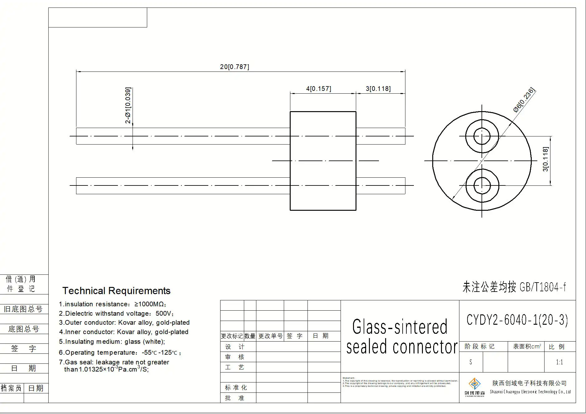
Procurement Guide: How to Buy High Pressure Multipin Feedthroughs
Identifying Qualified Suppliers and Distributors
When looking for high-pressure multipin feedthroughs from outside the United States, you have to evaluate suppliers based on three factors: their ability to make the feedthroughs, their quality systems, and their knowledge of how to use them. When it comes to the US, well-known distributors keep large stocks of basic setups and work with OEMs to create custom solutions. Because of the strong semiconductor and scientific instrument industries in Europe, many suppliers focus on ultra-high vacuum versions.
Asian firms, especially those in the Shaanxi and Guangdong areas in China, have become competitive sources that offer both good quality and good value. Advanced skills in hermetic sealing technologies and precision electrical connectors can be seen at places like Shaanxi Chuangyu Electronic Technology. Their production system can handle both large quantities of standard products and custom, non-standard assemblies. Each year, it can make up to 500,000 RF components.
When examining possible sources, ask for thorough paperwork that includes material approvals, leak testing methods, and dimensional limits. Suppliers who follow the GJB 2446A and MIL-DTL-83513 standards have quality systems that meet military standards. ISO 9001 certification shows that they know how to manage quality in a basic way.
Sample Evaluation and Customization Processes
Getting samples lets you test things out in real life before committing to production orders. Suppliers with a good reputation give evaluation samples away for free because they know that expert proof builds trust. The conditions of testing should be the same as they would be in real life, including changing pressures, high temperatures, and different types of electrical loads.
Customization takes into account the specifics of each project. Changes to the number of pins, different sealing materials, special finishes, and different flange setups are all common things that can be done. It is very important to communicate detailed specifications. You should include CAD drawings, environmental parameters, electrical requirements, and installation methods. Suppliers with a lot of experience, like Chuangyu, have engineering teams that can take application needs and turn them into optimized designs by using their knowledge of high-speed PCB integration and RF component development.
Timelines for prototyping range from two weeks for small changes to eight weeks for completely new designs. During this phase, collaborative design reviews find possible problems before tooling commitments are made. This keeps expensive revisions from being needed.
Pricing Structures and Lead Time Considerations
Pricing is based on how complicated, how much, and how customized the work is. Standard stock items range from $50 for easy 9-pin sets to $800 for 100-pin sets made of rare materials. Engineering fees for custom designs are usually between $1,500 and $5,000, which are spread out over the number of units that are made.
With volume prices, you can save a lot of money. When you buy more than 100 units, you can often save 20 to 30 percent, and when you buy 1,000 or more units, you need special tools and better ways to make the products. Costs stay stable with annual purchasing agreements, and capacity is protected in case of supply chain disruptions.
Standard goods have lead times of four to twelve weeks, and custom parts have lead times of sixteen weeks. Important projects can get faster handling at a higher cost. Shipping times should be taken into account by buyers. It takes 5–7 days for air freight to get from Asia to North America, but 4–6 weeks for ocean freight.
Logistics, Warranty, and After-Sales Support
The rules for packaging keep airtight seals safe while they are being shipped. To keep things from breaking, suppliers use moisture protection bags, foam padding, and rigid cases. When it comes to large orders or custom assemblies, insurance coverage should match the value of the goods.
The warranty usually lasts between twelve and twenty-four months and covers problems with the way the product was made but not damage caused by improper installation or exposure to environments that are too harsh. For important uses, extended guarantees are often possible.
After-sales service is what sets some providers apart from others. Long-term system reliability is ensured by technical help for installation problems, advice for regular inspections, and the availability of replacement parts. When it comes to response time, suppliers with regional service centers or partnerships with local distributors are better than those who only depend on help from headquarters.
Trusted Brands and Quality Certifications
Leading Manufacturers and Their Specializations
There are a lot of specialized producers in the high-pressure multipin feedthrough market, and each one has its own strengths. Established Western companies hold top positions thanks to decades of experience in aerospace and defense, and their products have been used in the toughest situations. Their engineering teams help make industry standards and keep large libraries of test data up to date.
Chinese makers have done a great job of matching international standards for quality while also offering affordable pricing. Shaanxi Chuangyu Electronic Technology is a good example of this change because it combines current production facilities with almost 20 years of process improvement. Their factory in the Xi'an Chang'an Innovation Technology Industrial Park has 1,000 square meters of specialized production space that is used for precise manufacturing, clever control systems, and full quality assurance. The company has a lot of experience with RF communication parts and semiconductor test probes. They offer custom solutions to the photovoltaic, medical, and automation industries.
Specialists in the area take care of niche needs. Manufacturers from Scandinavia are the best at cryogenic applications, Japanese companies are the best at making things smaller, and Israeli companies are the best at coming up with new high-temperature versions. Instead of relying only on name recognition, choices about what to buy should match the strengths of each supplier with the needs of each application.
Essential Industry Standards and Certifications
Quality marks give you objective ways to judge a seller. ISO 9001 certification sets a standard for quality management, including written methods, traceability, and systems for ongoing growth. Suppliers that want to work with aerospace companies usually have AS9100 approval, which includes risk management and configuration control standards that are unique to aerospace.
Material approvals check the mechanical qualities and alloy compositions. Stainless steels, nickel alloys, and specialty materials must meet ASTM standards, and ROHS compliance proves that no restricted substances are present. For biocompatibility confirmation, medical devices need to be certified by ISO 13485 and registered with the FDA.
Performance claims are backed up by testing certifications. Independent proof of hermeticity is provided by third-party leak testing that meets ANSI/NCSL Z540 standards. Voltage withstand, insulation resistance, and contact performance are all checked using electrical testing that follows IEC standards. Suppliers who keep approved calibration labs show that they care about the accuracy of measurements.
Validating Supplier Performance Through Due Diligence
Case studies and references from clients can help you figure out how reliable a supplier is. Ask for the contact information of customers who are using similar applications and ask them about delivery speed, how quickly technical support responds, and how reliable the product is in the long term. Not wanting to give recommendations is a sign of possible problems.
Facility audits show how well operations are running and how high the quality culture is. Through virtual tours or in-person visits, you can check out how advanced the equipment is, how clean it is, and how well the staff is trained. Check to see if staff follow written procedures and if measurement systems are regularly calibrated.
Financial stability affects the ability of a partnership to last for a long time. When suppliers are having money problems, they might lower the quality of their products, make lead times longer, or suddenly stop making certain lines of products. Check the company's credit score, yearly records, and payment terms to see how healthy it is.
Final Considerations and Best Practices for Buyers
Aligning Technical Features with Application Requirements
A thorough description of needs is the first step to a successful procurement. Pressure ranges, temperature variations, humidity exposure, vibration patterns, and chemical compatibility should all be listed as environmental factors. In electrical specifications, you need to list the voltage levels, current limits, signal types, frequency ranges, and impedance matching requirements.
Specification gaps can be avoided with an organized process. Think about the mounting orientation, panel thickness, type of mating connector, wire termination method, and ease of access for maintenance. For vacuum uses, you should list the minimum leak rate and bakeout temperature that are allowed. Installations that are under a lot of pressure need grades for burst pressure and check-along times for the seals.
Include technical teams from the start of the supplier selection process. Hardware design engineers can look at problems with mechanical interaction, test engineers can look at how well it works with current fixtures, and procurement managers can look at the total cost of ownership, which is more than just the purchase price. This way of working together finds potential problems before they get too big and cost a lot to fix.
Common Pitfalls and Risk Mitigation Strategies
Environmental underspecification leads to a lot of failures. Buyers don't always think about how mist cycling, salt spray exposure, or chemical fumes can damage seals and contacts over time. Without full environmental exposure, suppliers can't suggest the right products. If you're not sure, describe the worst-case scenarios and ask for proof of material suitability.
Skipping third-party testing and proof comes with a lot of danger. Test data from the manufacturer is useful, but independent validation by accredited laboratories gets rid of any potential conflicts of interest. This is especially important in safety-critical situations where a failed feedthrough could hurt someone or damage equipment badly.
Not following the right steps for fitting can damage even the best parts. Glass-sealed feedthroughs break when soldering temperatures go too high, contact pins bend when wires are inserted without the right tools, and sealing surfaces get crushed when mounting hardware is too tight. Make sure you get clear instructions on how to put the product, and ask the seller to train your support staff.
Building Strategic Supplier Relationships
Long-term relationships are more valuable than one-time deals. Preferred suppliers put time and effort into learning about your applications and will suggest ways to make them better as new technologies come out. They give you priority with your orders when they can't fill all of them at once and let you know ahead of time when products change or become obsolete.
Maintenance support makes products last longer and keeps systems running. Set up inspection plans that are right for the conditions of use. For example, check the insulation resistance every three months in damp places, the helium leak test every year for vacuum systems, and the contact resistance check every six months for high-current uses. Suppliers like Chuangyu help customers set up effective preventive maintenance plans by giving them expert advice on these steps.
Working together with suppliers is good for design evolution. As equipment is updated or new projects start, providers who already know your standards and tastes can speed up the development process. Their knowledge of applications helps improve new designs, which could save money and time compared to starting from scratch with vendors you don't know.
Conclusion
To choose the right high-pressure multipin feedthrough, you need to carefully look at the technical specs, sealing technologies, and provider skills. These important parts keep electrical connections and hermetic integrity while crossing pressure limits. This makes them necessary for use in aircraft, semiconductors, medicine, and industry. A good procurement process combines performance needs with cost concerns, giving priority to providers who can show they know how to make things, have quality certifications, and offer quick technical support. Buyers can get reliable parts that last a long time by learning basic design principles, comparing closing technologies, and forming smart partnerships with suppliers. Common risks are reduced by thorough specification creation, independent testing confirmation, and following the right installation processes. This makes sure that the system performs to the highest standards.
FAQ
1. What distinguishes high-pressure multipin feedthroughs from standard electrical connectors?
High-pressure multipin feedthroughs use glass-to-metal or ceramic-to-metal bonds for hermetic sealing, which stops gas or liquid from moving across pressure barriers. Standard plugs don't completely seal off the environment, so they let tiny leaks happen that aren't good for vacuum tanks, pressure vessels, or places that are sensitive to contamination. Extreme pressure differences can't damage the special construction, which keeps multiple electrical pathways open.
2. How do I verify leak rate specifications for vacuum applications?
Helium mass spectrometry is the standard way to find small leaks and is used in leak testing. For ultra-high-vacuum systems, suppliers should show test certificates that show leak rates are less than certain levels, usually 1×10⁻ atm·cm³/s or less. Independent testing by approved labs backs up what the seller says and meets the quality assurance needs of important uses. Periodic retesting during operation makes sure that the seal stays in good shape.
3. Can high-pressure multipin feedthroughs handle both signal and power transmission?
Modern designs can work with a variety of setups because they combine signal pins that can handle low currents with power contacts that can handle up to 13A. As a result, pin sizes vary: signal wires use smaller diameters to reduce capacitance and keep impedance matching, while power pins use bigger diameters to get rid of heat. Buyers should be clear about how much current each circuit needs so that the right-sized conductors and contact materials are used.
Partner with Chuangyu for Reliable High Pressure Multipin Feedthrough Solutions
Shaanxi Chuangyu Electronic Technology makes precise hermetic feedthroughs by combining cutting-edge sealing technologies with years of experience making things. Our wide range of products includes RF connectors up to 110 GHz, custom test probes, and multipin feedthrough systems made for tough pressure and vacuum conditions. We provide reliable, low-cost solutions to the photovoltaic, medical, aerospace, and semiconductor industries from our 1,000-square-meter facility in Xi'an, which is equipped with smart production systems and strict quality control protocols. Our engineering team works together to make sure that the products we sell work best for your needs, whether you need standard catalog items or completely unique designs. Email us at chuangyuwz01@cymicrowave.com to talk to experienced technical experts about your high-pressure multipin feedthrough needs. As a reliable maker and provider, we offer low prices, easy customization, and quick help for the whole lifecycle of your product.
References
1. Peterson, M.J., & Williams, R.K. (2021). Hermetic Sealing Technologies for Extreme Environments: Materials, Processes, and Applications. Aerospace Engineering Press.
2. Zhang, L., Chen, H., & Kumar, S. (2022). "Comparative Analysis of Glass-to-Metal and Ceramic-to-Metal Sealing for High-Pressure Electrical Feedthroughs." Journal of Electronic Packaging, 144(3), 031008.
3. American Society for Testing and Materials. (2020). ASTM F1606-20: Standard Test Method for Hermetic Seal on Glass, Ceramic, or Metal Packages. ASTM International.
4. Institute of Electrical and Electronics Engineers. (2019). IEEE Standard 1814-2019: Recommended Practice for Electrical Feedthroughs Used in High-Pressure and High-Vacuum Environments. IEEE Standards Association.
5. Thompson, A.R., & Martinez, D.L. (2023). "Reliability Prediction Models for Multipin Feedthrough Assemblies in Downhole Oil and Gas Applications." SPE Drilling & Completion, 38(1), 112-127.
6. International Organization for Standardization. (2018). ISO 3529-3:2018 Vacuum Technology — Vocabulary — Part 3: Vacuum Seals and Associated Elements. ISO Publications.
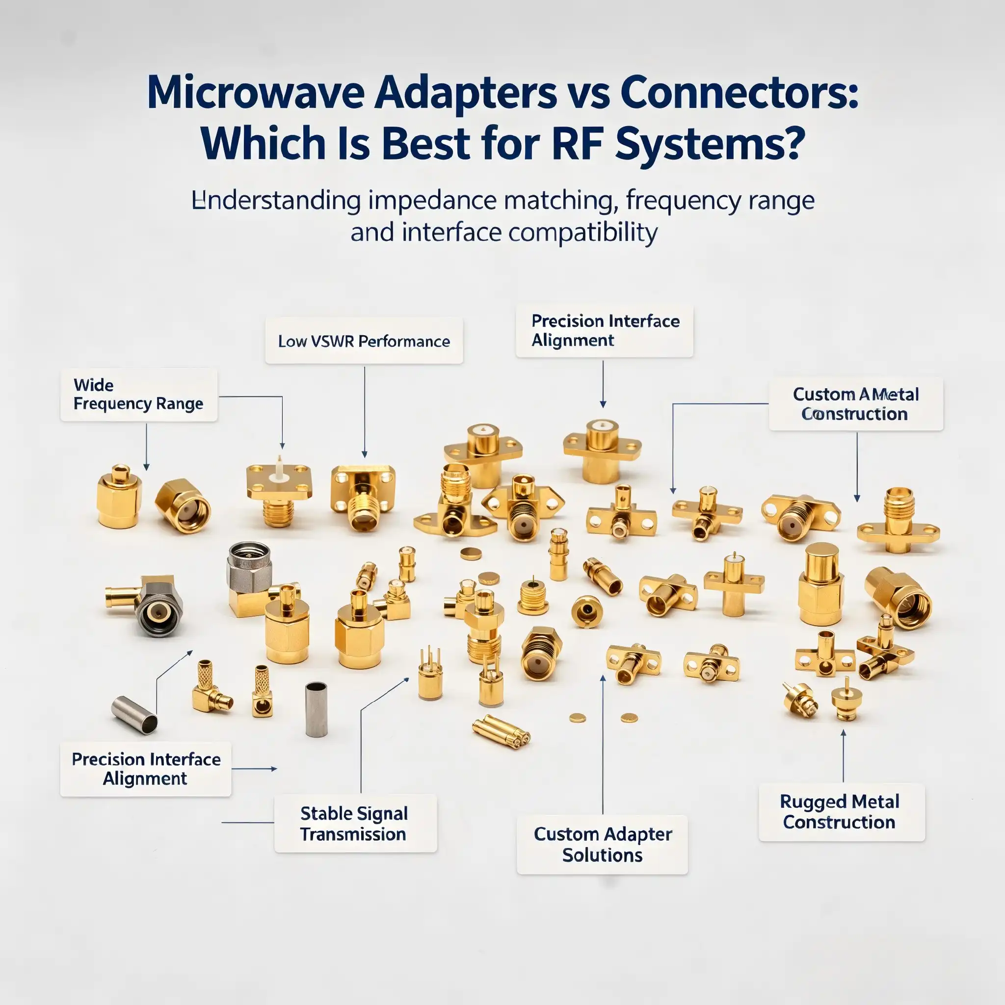
When designing RF systems, the choice between microwave adapters and connectors can significantly influence signal integrity and system performance. Microwave adapters serve as interface converters, bridging mismatched connector types—such as converting SMA to N-Type or BNC to SMA—ensuring compatibility across diverse components. Connectors, conversely, provide the primary signal pathway, establishing stable, low-loss connections between cables and equipment. Both play essential but distinct roles in maintaining reliable signal transmission, particularly in high-frequency applications up to 110 GHz.
Introduction
Microwave adapters and plugs are important parts of RF systems that make sure signals are sent correctly and the system works well. Choosing the right solution is very important for procurement professionals, engineers, and OEMs who work in the B2B sector to maintain performance standards and reduce downtime. The goal of this guide is to make the differences between microwave adapters and plugs clear, explain what each one does, and give you useful information that you can use to make smart purchasing choices that meet your technical and financial needs. Technical teams can avoid making mistakes that cost a lot of money, keep signals from getting weaker, and make RF systems that meet strict requirements in areas like semiconductors, medical device manufacturing, telecommunications, and solar tests by understanding these differences.
Microwave Adapters vs Connectors: Key Differences and Performance Comparison
This part compares microwave adapters and connectors in great detail, paying special attention to signal quality, frequency range, durability, and upkeep. Procurement managers can make smart choices when they know how important factors like insertion loss and return loss affect the overall performance of an RF system in uses like 4G/5G networks. To help with choices about working reliability and lifetime costs, mechanical robustness and ease of installation are considered.
Signal Quality and Electrical Performance
In RF system design, signal quality is still the most important thing. Because they create straight signal paths without converting them, connectors usually have smaller insertion loss than adapters. At frequencies up to 18 GHz, good connections keep insertion loss below 0.1 dB. However, microwave adapters add extra loss—usually between 0.15 dB and 0.3 dB—because of the interface change. The efficiency of return loss follows a similar trend, with connectors usually getting better VSWR numbers than adapters. But in many situations, well-made adapters from reputable companies can match the performance of connectors. When you stack multiple adapters on top of each other, losses add up and could lower the signal quality in long cable assemblies or complicated test setups. To make sure that performance margins are acceptable, engineers must carefully calculate total system loss budgets.
Frequency Range and Application Suitability
Connectors are designed to work with certain frequency ranges, which makes them very good at what they're supposed to do. SMA connections work reliably from DC to 18 GHz, and some high-precision versions can even work at 26.5 GHz. N-Type plugs work well with power and cover DC to 11 GHz. For millimeter-wave uses, specific connections like 2.92 mm and 2.4 mm can work up to 40 GHz and 50 GHz, while 1.85 mm and 1.0 mm connectors can handle up to 67 GHz and 110 GHz, respectively. It is harder to build microwave adapters because they have to work well across two different connector interfaces and maintain their performance over their frequency bands. It is possible that between-series connections have smaller useful bandwidths than individual connectors. This is especially true at higher frequencies, where small differences in size become very important. Choosing adapters that are rated for frequencies that are much higher than your real working range gives you performance headroom and makes sure that the system will work reliably.
Durability and Mechanical Robustness
Lifecycle costs and system stability are directly linked to how long something lasts mechanically. Connectors made to be used in the field are made to last. They have strong bodies made of brass or stainless steel, gold or silver plating, and sealed surfaces that keep out moisture, dust, and rust. A lot of industrial-grade connectors can be mated hundreds or even thousands of times without losing their effectiveness. Since microwave adapters are passive interface converters, they usually handle less mechanical stress than connectors at the ends of cables or at the points where equipment connects. However, adapters in test rooms may connect and disconnect many times, which is why mating cycle scores are important. Premium adapters have housings made of stainless steel and center contacts made of beryllium copper, so they last as long as high-end connections. When used over and over, cheap adapters made of brass with thin plating may wear out quickly, causing connections to drop out and signal interruptions that make troubleshooting harder.
Procurement Insights and Cost Considerations
Prices for microwave adapters and plugs vary a lot depending on the frequency range, the materials used, the level of precision, and the name of the maker. Precision millimeter-wave connections can cost more than $100 each, while standard SMA connectors may only cost a few dollars per piece. Adapters that work between series usually cost between $10 and $50, but high-frequency versions cost a lot more. Buying in bulk can save you a lot of money. When you order more than 100 pieces, you can usually get a 20% to 40% discount. You should also look at the warranties that the supplier offers; reputable makers offer performance guarantees and will repair broken parts, which lowers the total cost of ownership. Check a supplier's quality certifications, measurement tools, and expert help resources before choosing one. Well-known brands have large application libraries and engineering teams that can help you choose the right product, which could save you hours of research time.
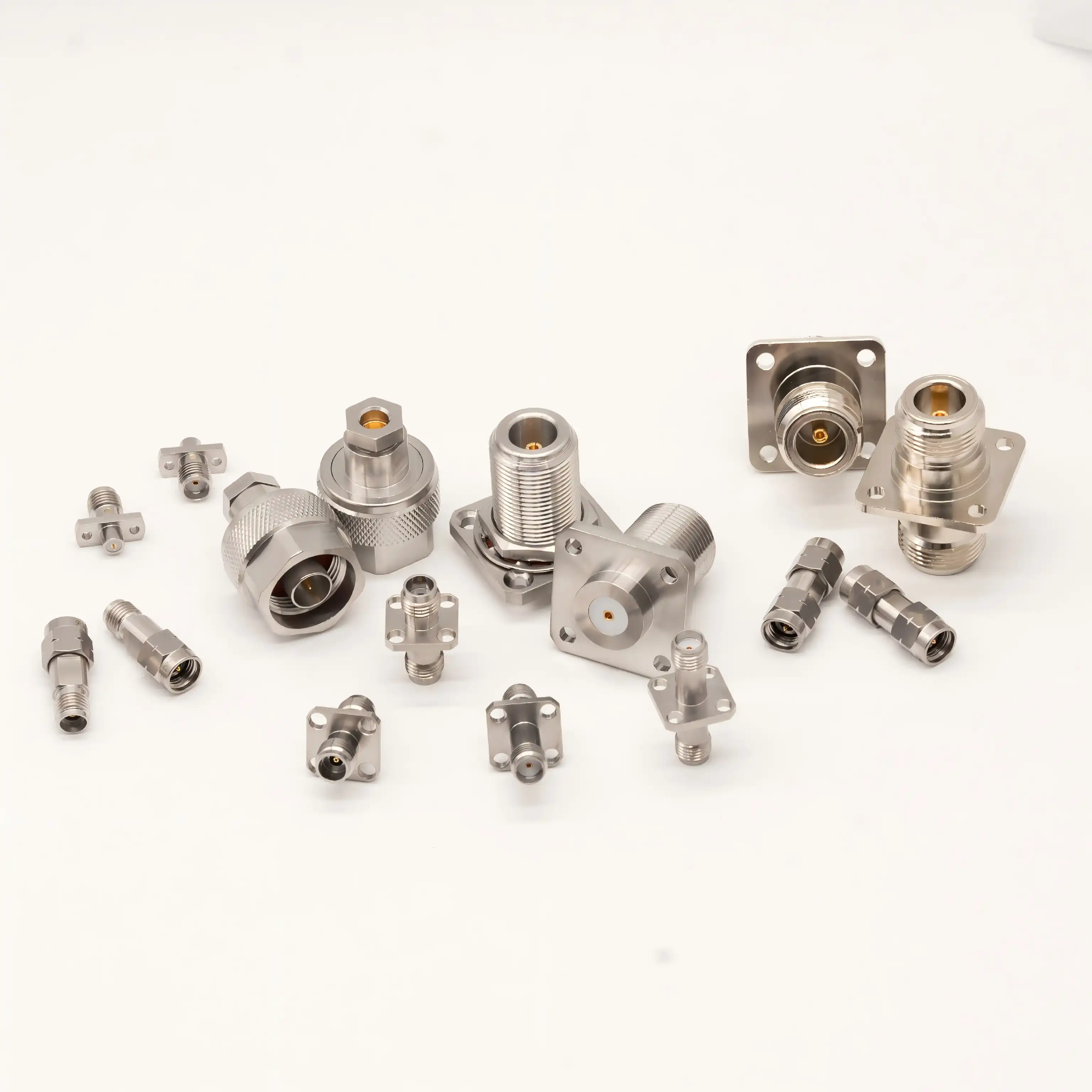
How to Choose the Best Option for Your RF System
Before you can choose the best adapter or connector, you need to know what your system needs, such as frequency, environment, and budget. This method helps procurement teams and design engineers make decisions by walking them through the evaluation process. It helps them find the best balance between technical performance and cost-effectiveness, while also making sure that the product will last for a long time.
Assessing Your System Requirements
Start by writing down the electricity requirements for your device. In what frequency range does your RF system need to work? Are you making things for 5G bands below 6 GHz, millimeter-wave frequencies above 24 GHz, or specific uses that need performance above 50 GHz? Connector and microwave adapter choices are directly based on frequency needs. Power levels are also important. For example, high-power transmitters need strong connectors that can work nonstop without breaking down or arcing. The environment affects the choice of materials. For example, outdoor installations need weather-sealed connectors with finishes that do not rust, while standard grades can be used for lab equipment. There are fewer choices for components because of mechanical issues like room limitations, mounting arrangements, and expected mating cycles. Making a thorough needs matrix helps make sure that all important factors are taken into account before a purchase is made.
Evaluating Leading Manufacturers and Product Portfolios
The market for microwave adapters and connectors is dominated by a few big names. Amphenol has a wide range of products that meet business and military requirements, and they can be customized in a lot of ways. Pasternack keeps a lot of adapters and plugs in stock and can ship them the same day. This makes them useful for making prototypes and fixing things quickly. Radiall is an expert in making high-quality parts for defense, communications, and aerospace. They are especially good at making millimeter-wave connectors. TE Connectivity offers low-cost options for high-volume uses, matching good performance with low prices. When looking at different manufacturers, it's important to read their technical datasheets very carefully. Specified values for insertion loss, return loss, and frequency range should include test conditions and measurement uncertainty. Manufacturers who offer a lot of application support, like 3D CAD models, S-parameter files, and integration guidance, make it easier to qualify their products and get them on the market faster.
Customization Capabilities and Non-Standard Solutions
Most RF system needs can be met by standard catalog parts, but some applications may need custom adapters or connectors. Custom non-standard electrical component manufacturers, like Chuangyu, give custom solutions for different interface needs, wider frequency ranges, or unique mechanical setups. Custom adapters are especially useful for connecting old equipment to new systems or making the most of setups that do not have a lot of room. Usually, the customization process starts with in-depth technical talks about electrical needs, mechanical limitations, working conditions, and expected volume. Testing can be done on prototypes before committing to production tools. Custom parts cost more per unit and take longer to get than standard parts, but they do not have any compromises that could hurt system performance or make installation more difficult.
Installation Guide and Best Practices for Microwave Adapters and Connectors
To get the most out of microwave adapters and connectors, they need to be installed and maintained correctly. Following systematic processes lowers the variability of connections, stops harm, and increases the lifespan of components. This lowers the total cost of ownership and makes the system more reliable.
Pre-Installation Inspection and Preparation
Before you install any microwave adapter or connector, you should look it over very carefully. Look for damage, distortion, or pollution in the center contacts. Cross-threading, dirt, or rust on connection threads could make them not fit together properly. Check the barrier materials for cracks or changes in color that could mean heat damage or water getting in. Use the right tools to clean all the contact surfaces. Lint-free swabs with isopropyl alcohol work well for most jobs, but RF connector cleaning kits may be needed for tough dirt. Do not use rough materials that could scratch plated surfaces or hurt precision-machined parts. Make sure that the types of connectors and adapters you're using meet your needs. Mixing connection families that do not work together or using the wrong gender pairs can damage the signal and make it less useful. Protective caps should be kept on connectors that aren't being used to keep dust from building up and to avoid mechanical damage during storage.
Correct Mounting Techniques
Using the right amount of torque makes sure that mechanical and electrical links work well without hurting any parts. If you tighten something too much, the center contact pins get crushed, the insulators get deformed, and the connector bodies may crack. If you tighten something too little, holes form that make insertion loss and VSWR worse. When using torque tools, make sure they are set to the manufacturer's recommended settings. For SMA connectors, these are usually 7 to 12 inch-pounds, and for N-Type connectors, they are usually 12 to 15 inch-pounds. Smaller connectors, like MMCX and U.FL, need to be handled carefully. To connect these snap-together types, apply light axial pressure until you feel the detent engage. When putting in bulkhead or panel-mount connections, make sure the holes are the right size and the surface is flat. If they aren't, mechanical stress could cause insulators to crack or center contacts to become out of alignment. Apply anti-seize powder to threads on outdoor setups to make them easier to separate in the future and stop galvanic corrosion between metals that are not the same.
Post-Installation Testing and Validation
After installation, make sure the system works by taking the right measurements. To find out the return loss and insertion loss for your working frequency range, use network testers that have been calibrated. Check the measured values against the component specs and the system requirements. If there is a big difference, it means that there are installation issues, damaged components, or connections that do not work with each other. Time-domain reflectometry can precisely locate impedance discontinuities, which can help find and fix small connection problems that lower signal quality. Keep an eye on the temperatures of connectors while they're working in high-power systems. If they get too hot, it could mean that the connections are bad, there is contamination, or there are impedance mismatches that focus RF energy. Write down the initial measurements so you can use them again in the future. Changes in performance over time could mean that there is wear, corrosion, or environmental damage that needs maintenance.
Troubleshooting Common Issues
Signal loss is often caused by interference, mechanical damage, or differences in resistance. If the measures show that the insertion loss has gone up, you should unplug everything and check all of the connections for dirt, oxidation, or broken center contacts. Before replacing parts, clean and try again. Intermittent connections that make measures less accurate are usually a sign of worn contact surfaces, loose mounting hardware, or cable flex damage close to the connectors. It's possible for impedance discontinuities to be caused by the wrong type of connector, damaged insulators, or bad mating if the VSWR is high or the return loss is low. When using MMCX-to-SMA connectors or SMP female-to-female adapters, you need to make sure they are compatible. Mixing connector families without the right adapters can cause problems that slow things down. When fixing problems with complicated systems that have many adapters, check each connection separately to find the source of the issue instead of replacing whole assemblies.
Future Trends and Innovations in Microwave Adapters and Connectors
As 5G rolls out and new technologies come out, the RF scene changes quickly. This means that microwave adapters and connection designs must always come up with new ideas. Understanding these trends helps buying teams make decisions that look to the future. This way, they can make sure that the choices they make about components will still be useful as technology changes and that long-lasting goods do not become obsolete too soon.
Material Advancements and Miniaturization
Next-generation connectors are made from new materials that make them smaller and lighter while also improving their electrical performance. At millimeter-wave frequencies, signal loss is kept to a minimum by low-loss dielectrics such as PTFE composites and ceramic insulators. For sensitive receiver applications, new contact plating formulations make the materials last longer and cut down on passive intermodulation. As 5G devices, IoT monitors, and medical tools that you wear get smaller, miniaturization keeps going. Ultra-compact connectors that are almost half the size of standard designs allow circuit boards to have more components while still maintaining electrical performance. But smaller ports usually cannot handle as much power and can only mate a certain number of times. This means that application needs must be carefully weighed against size limitations.
Enhanced Integration and Smart Connectivity
New RF system designs include microwave adapters and connectors that have sensors and identification features built in more and more. RFID-tagged connectors make it possible to automatically manage inventory in large installations. They keep track of where parts are, when they were installed, and how many times they've been mated, which helps predict when maintenance needs to be done. Some experimental designs use temperature sensors to keep an eye on the temperature of the connectors and let the designers know early on when problems are starting to happen. These new ideas are still mostly just study, but they point the way toward better RF infrastructure that checks its own performance, predicts problems before they happen, and shuts down the system. Purchasing departments should keep an eye on these changes and work with makers who are thinking outside the box and investing in new technologies.
Adapting to New Industry Standards
Standards in an industry are always changing to meet new wants. New developments include connectors that work best with 77 GHz automotive radar systems that need to be very stable in terms of phase across a wide range of temperatures. More and more companies that make medical devices are asking for connections that meet strict biocompatibility standards for both internal and wearable devices. Photovoltaic test equipment needs connectors that can withstand being outside while still maintaining their precise electrical properties. Using industry groups, technical workshops, and maker technical bulletins to stay up to date on the development of standards helps procurement teams plan for changes and choose parts that meet future needs instead of yesterday's.
Conclusion
To choose between microwave adapters and connectors, you need to know what each does in an RF system. Connectors are the main ways that signals get from one part to another, and they work best when they're coupled with adapters, which change the contact so that different parts can work together. Both need a close look at the frequency range, insertion loss, mechanical longevity, and how well they work in the surroundings. When buying something, you should think about both the short-term technology needs and the long-term dependability and cost needs. Partnering with makers that offer a wide range of products, the ability to customize them, and strong expert support makes it easier to choose the right parts and put the system together. Keeping in touch with cutting-edge suppliers is important if you want to keep your systems competitive as RF technology moves toward higher frequencies and more complex designs.
FAQ
1. What are the key performance factors for microwave adapters?
Insertion loss is an important performance factor for microwave adapters. It should usually stay below 0.3 dB across the working frequency range to keep system cascade signals from getting weaker. The quality of impedance matching is measured by return loss. Values above 20 dB ensure that signal reflections are kept to a minimum. Usable bandwidth is based on frequency compatibility. To get better performance, choose adapters with ratings higher than your highest working frequency. Reliability and lifecycle costs are affected by mechanical robustness, which includes mating cycle ratings and the quality of the materials. In emitter uses, being able to handle a lot of power is important to avoid thermal damage or arcing when RF power levels are high. Knowing about these things helps buying teams choose devices that maintain signal integrity in the RF system.
2. Are microwave adapters and connectors interchangeable?
Even though they look a lot alike, microwave connections and plugs do not always work with each other. Adapters are specially made to convert interfaces, working with different types of connectors while keeping the electrical performance at a good level. Connectors are the main way that cables, equipment, and circuit boards send and receive signals. They are designed to have the least amount of signal loss and the longest life possible. When you use an adapter instead of a good connection, you lose insertion loss and could have reliability problems. On the other hand, connections cannot work as adapters do, which is to change the interface. Before replacing parts, make sure they are compatible by checking the connector types, genders, impedances, and frequency ranges. Looking at datasheets and technical support resources from suppliers can help you choose the right parts for each job.
Contact Chuangyu for Premium Microwave Adapters and RF Solutions
Shaanxi Chuangyu Electronic Technology is an expert in high-precision radio frequency (RF) parts. They provide a full range of microwave adapters, millimeter-wave connectors up to 110 GHz, and custom wire kits made to your exact requirements. Our factories in Xi'an follow strict quality standards and send 500,000 RF components to top companies that make semiconductors, medical devices, telecommunications equipment, and solar panels every year. Our engineering team can help you from the first idea to mass production, whether you need between-series adapters for test equipment, SMP female-to-female adapters for high-density assemblies, or custom non-standard solutions for difficult interface problems. We keep a large collection on hand so that we can serve quickly, and we can also customize our products to meet specific needs that normal catalogs cannot meet. Reach out to our team at chuangyuwz01@cymicrowave.com to talk about your project needs with experienced application engineers who know how hard it can be for RF system builders to get the parts they need.
References
1. Pozar, David M. Microwave Engineering, 4th Edition. Hoboken: John Wiley & Sons, 2012.
2. Harsany, Steven C. Principles of Microwave Technology. Upper Saddle River: Prentice Hall PTR, 1997.
3. Hickman, Ian. Practical RF Handbook, 4th Edition. Oxford: Newnes, 2007.
4. La Verghetta, Thomas S. Modern Microwave Measurements and Techniques, 2nd Edition. Boston: Artech House, 2000.
5. Vendelin, George D., Anthony M. Pavio, and Ulrich L. Rohde. Microwave Circuit Design Using Linear and Nonlinear Techniques, 2nd Edition. Hoboken: John Wiley & Sons, 2005.
6. Ludwig, Reinhold, and Gene Bogdanov. RF Circuit Design: Theory and Applications, 2nd Edition. Upper Saddle River: Pearson Prentice Hall, 2009.
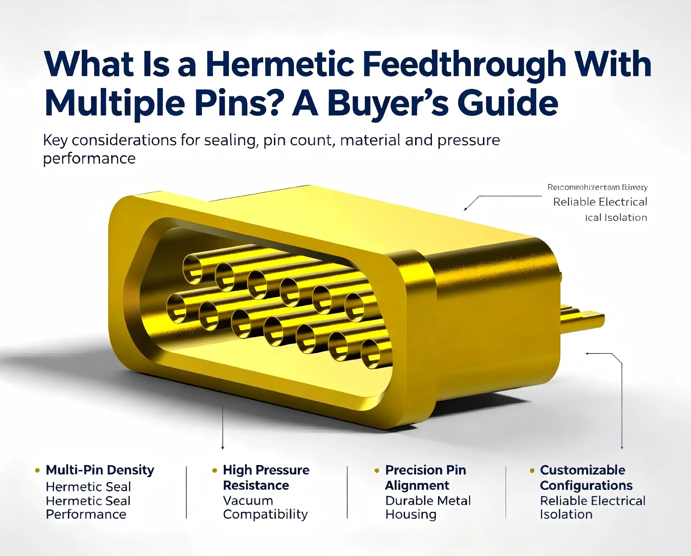
A hermetic feedthrough with multiple pins is a precision electrical component that enables the transmission of electrical signals, power, or data through a sealed barrier while maintaining complete environmental isolation. Unlike standard connectors, these devices create airtight or vacuum-tight seals using advanced technologies such as glass-to-metal or ceramic-to-metal bonding. They prevent gas, moisture, and contaminants from penetrating sensitive enclosures, making them indispensable in aerospace, medical implants, semiconductor testing, and industrial automation where even microscopic leaks can compromise system integrity and performance.
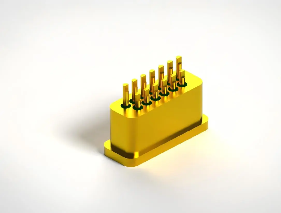
Comparing Hermetic Feedthroughs With Multiple Pins
Multiple-Pin vs. Single-Pin Configurations
When looking at different hermetic feedthroughs with multiple pin choices, it is important to know the pros and cons of both consolidated multi-pin assemblies and distributed single-pin installs. When systems need to connect to a lot of electrical devices, multiple-pin designs make installation easier, take up less space, and cost less to put together. There is a lot less space on the panel for a 37-pin feedthrough than for 37 separate single-pin units, but the sealing performance is the same or better. But single-pin feedthroughs are better for keeping high-power wires separate from sensitive data lines. This stops electromagnetic interference and thermal coupling between circuits that are next to each other.
Feedthroughs vs. Bulkhead Connectors
It's common for procurement managers to mix up hermetic feedthroughs and normal bulkhead connections, but they are actually very different. Bulkhead connectors allow mechanical attachment and electrical continuity, but they rarely achieve true hermetic sealing. Over time, small amounts of gas can pass through elastomer seals. Electric feedthroughs have permanent glass or ceramic seals that stay in place even after decades of changing temperatures and pressures. This difference is very important in situations like medical implants or space systems, where any damage to the seal could cause unacceptable risks.
Glass vs. Ceramic Insulation Materials
Choosing between glass-to-metal and ceramic-to-metal feedthroughs affects both how well they work and how much they cost. Glass sealing technology has lower production costs and better sealing performance for uses below 250°C that need a modest amount of power, less than 1000V. Ceramic insulators have a dielectric strength of more than 10kV, can handle temperatures higher than 400°C, and last longer when subjected to vibration and shock loading. Engineers who work on RF microwave systems often choose ceramic designs because they have lower dielectric loss and can keep signals intact in high-frequency situations up to 40 GHz.
Design Challenges in High Pin Count Assemblies
Adding more conductors to hermetic enclosures makes engineering more difficult, which affects how reliable and easy to make the product is. Mismatches in thermal expansion between pins that are close to each other can cause damaging forces during temperature cycles, which could cause insulator materials to crack. To get the same quality seal on 50 or 100 glass-metal contacts at the same time, precise tools and process control are needed, which drives up the cost of production. As the space between conductors gets smaller, it gets harder to keep them electrically separate. This means that when putting the parts together, you have to pay close attention to the insulator's thickness and any surface contamination.
How to Choose the Best Hermetic Feedthrough With Multiple Pins
Defining Environmental Operating Conditions
To choose the right hermetic feedthrough with multiple pins, you must first carefully describe the operating environment your system will be used in. Extreme temperatures affect how well materials work together and how seals are made. For example, cryogenic medical uses close to -196°C need different solutions than geothermal tracking at +300°C. Whether there is a vacuum at 10⁻⁶ Torr or high pressure at 15,000 PSI, the difference in pressure across the seal contact affects the thickness of the housing wall and the shape of the seal. Chemical exposure to corrosive fluids, cleaning solvents, or reactive gases means that the housing and insulator parts need to be made of the right materials to keep them from breaking down too quickly.
Electrical Specification Requirements
By giving exact electrical details, you can be sure that the multi-pin hermetic feedthrough you choose will meet the performance needs of your system without adding too many extra costs. The minimum conductor cross-sectional area is set by the amount of current it needs to carry. For signal applications, this is usually 1A per pin, and for dedicated power contacts, it's 13A. Ratings for voltage must take into account both working potentials and short-term surges, with adjustments made for altitude and contamination levels. Specifications for insulation resistance, usually 5000MΩ or higher, make sure that there aren't too many leakage currents between wires that are next to each other and from active pins to ground.
Pin Count and Physical Arrangement
To find the best amount of wires and the best way to lay them out, you have to balance cost, density, and system design. Choosing extra pins gives you more options for making changes to the design in the future, but it also raises the initial costs and footprint. Pin setups range from straight lines that work for connecting ribbon cables to circles that fit standard mil-spec connector shapes, making it easier to choose the right connector. The type of contact—whether pins stick out for plug mating or sockets accept male contacts—affects both how strong the mechanical system is and how easy it is to put together in the field.
Evaluating Customization vs. Standard Products
Standard stock items from well-known companies have quicker wait times (usually 4 to 6 weeks) and lower unit costs for tried-and-true designs. However, custom hermetic feedthroughs are the best option when standard configurations don't work with certain mounting dimensions, pin counts that aren't normal, or special materials. Chuangyu specializes in unique, non-standard probe and connector solutions. They use their nearly 20 years of technical experience to make feedthroughs that exactly meet the needs of the application. When off-the-shelf parts don't work in solar testing systems, semiconductor equipment, or medical devices, our team works closely with R&D experts to make custom solutions.
Testing and Quality Verification Standards
Thorough testing procedures prove that hermetic seals will work reliably for decades of product lifecycles. Using mass spectrometers to test for helium leaks can find leak rates as low as 10⁻¹⁰ Torr·L/sec, which proves the seal's integrity far beyond what is normally required. Electrical performance testing checks the response of the insulator to stress conditions like high humidity and temperature, as well as the ability to handle voltage. In mechanical testing, parts are put through routines of vibration, shock, and temperature cycles that mimic the worst possible service conditions. This finds possible failure modes before they are put into use in the field.
Manufacturing and Design Considerations
Precision Assembly Processes
To make a high-reliability hermetic feedthrough with multiple pins, the process has to be carefully controlled at every stage of production. Before choosing a raw material, its chemical makeup and size must be checked to make sure they will work with the closing steps that will follow. Precision grinding is used to get glass or ceramic insulators to very tight standards, usually within ±0.025mm. This makes the exact shapes needed for hermetic bonding to work. Before heating cycles melt glass or activate brazing alloys, pin alignment fixtures place conductors with micron-level accuracy. This creates the permanent seals that determine how well the product works.
In our 1,000-square-meter plant in Xi'an, Chuangyu has dedicated production lines for making coaxial connectors, RF wire assemblies, and glass-sealed feedthrough components. Our 800-square-meter production workshop has the precise tools needed for Kovar alloy glass encapsulation processes. This lets us make 500,000 RF components every year that meet the high-quality standards needed by top photovoltaic companies and phone companies.
Managing Thermal Expansion and Mechanical Stress
Matching the coefficient of thermal expansion (CTE) of the conductors, insulators, and housings is very important for long-term reliability when temperatures change. Kovar metal housings have CTE values that are very close to those of borosilicate glasses. This means that they don't have to deal with as many thermal stresses during factory heating cycles or changes in service temperature. When used with carefully chosen brazing metals and ceramic insulators, the same level of stress control can be achieved at higher temperatures. To make sure that maximum tensile stresses stay below material failure levels even during rapid thermal transients, design engineers must use finite element analysis tools to figure out stress patterns.
Electromagnetic Shielding and Signal Integrity
Electromagnetic interference (EMI) suppression and signal path impedance control need to be carefully thot out for high-frequency electrical systems. Multi-pin hermetic feedthroughs for RF microwave uses have grounded metal housings that block outside interference by more than 85dB, keeping sensitive measurement circuits from being affected. The characteristic impedance for controlled-impedance signal routes is based on the spacing between the conductors and the dielectric properties of the insulator. This is important for keeping the signal integrity in gigahertz-range uses. Putting ground pins in multi-conductor groups helps keep crosstalk between neighboring signal channels that carry fast-edge-rate digital data or analog sensor information to a minimum.
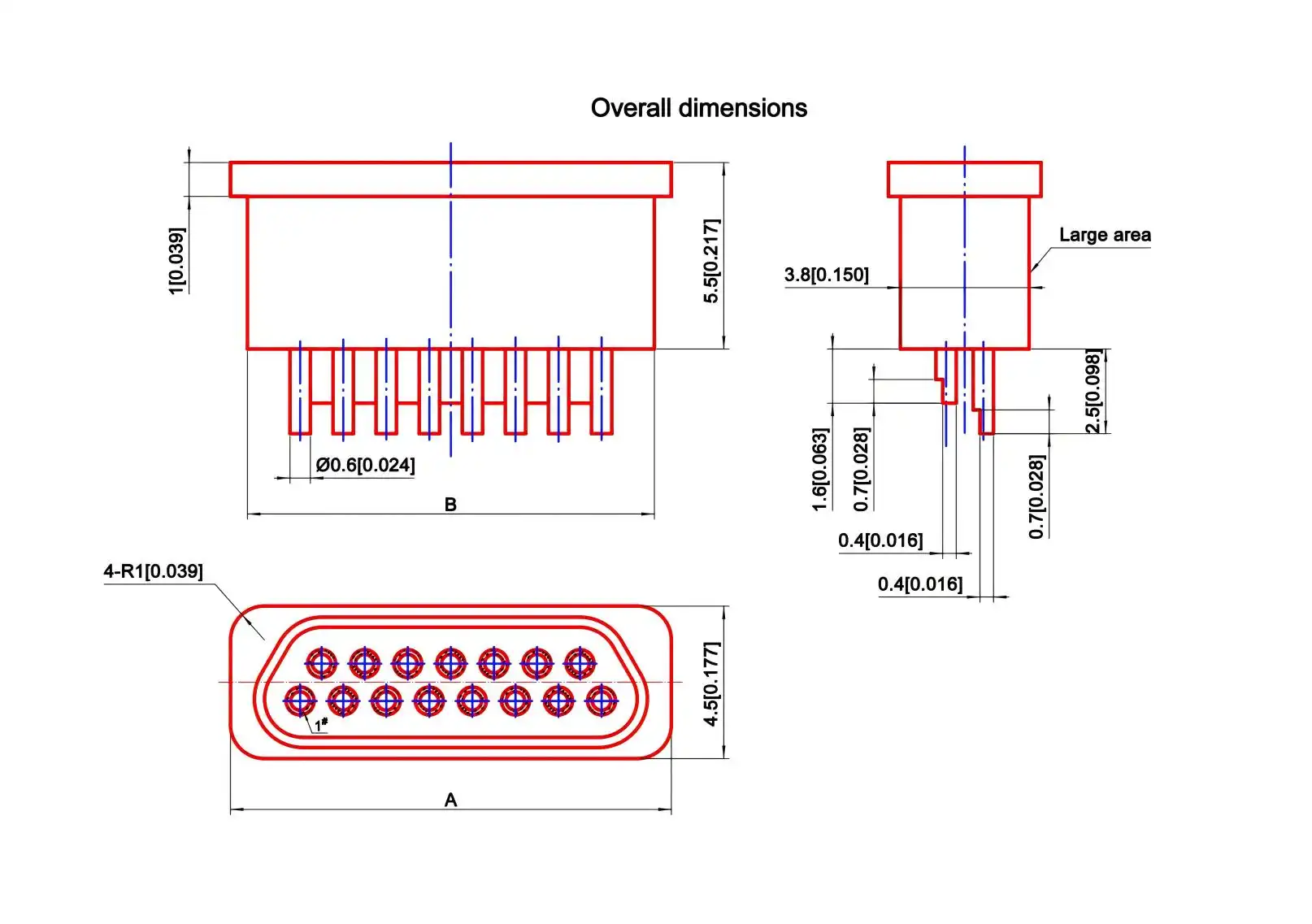
Procurement Guide for Hermetic Feedthroughs With Multiple Pins
Identifying Reliable Suppliers and Manufacturers
To find hermetic feedthroughs with multiple-pin components, you need to find suppliers who have both technical know-how and a track record of delivering high-quality products. Authorized distributors of well-known brands like TE Connectivity, LEMO, and Fischer Connectors sell catalog items that have a history of dependability and come with a lot of technical information. OEM manufacturers that focus on custom designs offer technical help for solutions that are made for specific needs. They work together to improve specifications and lower the overall cost of the system. Checking that suppliers have certifications like ISO 9001 quality management and AS9100 aerospace standards helps make sure that manufacturing processes are strong and that products can be tracked.
The company Chuangyu makes precise parts and works with engineers to come up with special solutions that solve problems in the new energy, medical, and telecoms sectors. Because we are in the Xi'an Chang'an Innovation Technology Industrial Park, we have access to strong supply chain networks that let us get raw materials and finished products faster than the average in our industry by over 20%. This business efficiency directly leads to faster turnaround times for prototypes and faster production ramp-ups for product launches that need to happen quickly.
Understanding Pricing Factors and Lead Times
A big part of the price of a hermetic feedthrough is how much the materials cost. Compared to normal materials, valuable metal contacts, high-purity ceramics, and specialty alloys cost more. Customization that is too complicated, like non-standard pin configurations, strange mounting flanges, or specific sealing needs, adds to engineering time and tooling costs, which affects the cost per unit. The number of units ordered has a big effect on the price. Usually, prices break at 100, 500, and 1,000 units because set labor costs are spread out over longer production runs.
Standard catalog items usually ship 4 to 8 weeks after an order is placed. Custom designs, on the other hand, take 8 to 16 weeks, depending on how complicated they are and how busy the factories are at the moment. For urgent needs, there are options for expedited manufacturing, but extra fees of 25 to 50 percent usually apply. Strategic buyers place framework orders that set prices and delivery dates for expected yearly amounts. This secures production capacity and good prices while keeping their options open by releasing goods at times that match real consumption.
Custom Design vs. Catalog Product Decision Framework
When deciding between custom-engineered hermetic feedthroughs and normal stock items, you need to look at the total costs of ownership, which go beyond the initial purchase price. Custom designs improve performance and integration for specific uses, which could lower the cost of assembly, make the system more reliable, or make it possible to do things that aren't possible with standard parts. But the costs of development and the low minimum order quantities (usually 50 to 100 units for custom designs) mean that catalog products are better for low-volume uses or early stages of development.
Custom engineering works best for uses that need to be protected from certain environments, have special electrical needs, or have specific mounting needs. Our Chuangyu team is very good at turning application needs into optimized feedthrough designs. They do this by using their many years of experience with photovoltaic test probes, semiconductor testing fixtures, and medical device interconnects. We support customers throughout the entire lifecycle of a product by offering variable minimum order amounts that can be used for both prototyping and mass production.
After-Sales Support and Documentation Requirements
The successful coupling and ongoing supportability of hermetic feedthrough components are made possible by comprehensive technical documents. Good sellers give thorough datasheets that list electrical rates, mechanical measurements, building materials, and limits for environmental performance. Assembly mistakes that could damage the seal's integrity can be avoided by following installation instructions that include torque recommendations, mounting suggestions, and information on how to make sure the connectors fit together properly. For important uses, test results that show measures of voltage withstand, insulation resistance, and leak rates help with quality control and keeping track of the product.
The warranty lasts for 12 to 24 months and covers problems with the way the product was made. It does not cover damage caused by poor fitting, mechanical abuse, or using it beyond its recommended limits. Access to technical support, whether through application engineers, online resources, or field service staff, is very helpful for fixing problems with integration or making the system run more efficiently. Chuangyu gives companies ongoing engineering help and a 200-square-meter research and development (R&D) lab to back it up. Performance is checked for each application before full production commitment.
Conclusion
During the buying process, choosing the best hermetic feedthrough with multiple pins means matching the needs of the environment, electrical requirements, physical limitations, and business concerns. By learning about closing technologies, material qualities, and design tradeoffs, you can make smart choices that will give you years of reliable service in tough situations. Whether you're looking for catalog items from well-known names or working with specialized makers to make custom solutions, you need to carefully look at the skills, quality systems, and technical support of your suppliers to make sure the project goes well. Choosing the right components is an investment that pays off in the form of fewer failures in the field, easier assembly processes, and better system performance that meets the ever-stricter requirements of the industry.
FAQ
1. What differentiates hermetic feedthroughs from standard electrical connectors?
Standard electrical connections allow for mechanical attachment and electrical continuity, but small amounts of gas can leak through elastomer plugs, with leak rates usually around 10⁻³ to 10⁻⁴ Torr·L/sec. Hermetic feedthroughs with multiple pins use permanent glass-to-metal or ceramic-to-metal sealing technologies to keep leak rates below 10⁻⁹ Torr·L/sec. This gives vacuum systems, pressure vessels, and biomedical implants the complete environmental isolation they need.
2. How long do multi-pin hermetic feedthroughs last in harsh industrial environments?
When properly chosen and set up, hermetically sealed connectors usually work well for 20 to 30 years in tough situations. When used within certain temperature ranges, glass and ceramic seals stay stable through millions of thermal cycles. Service life rests mostly on keeping mechanical damage to a minimum during installation and staying away from chemicals that break down housing materials instead of seals.
3. Can multi-pin feedthroughs be customized for specific voltage or current requirements?
You can customize the conductor size to handle currents ranging from milliamps to tens of amps per pin, the insulator material to handle voltages ranging from hundreds to tens of thousands of volts, and the coatings or contact materials that work best with certain signal types or environments. Leading makers offer a lot of design options that maintain airtight integrity.
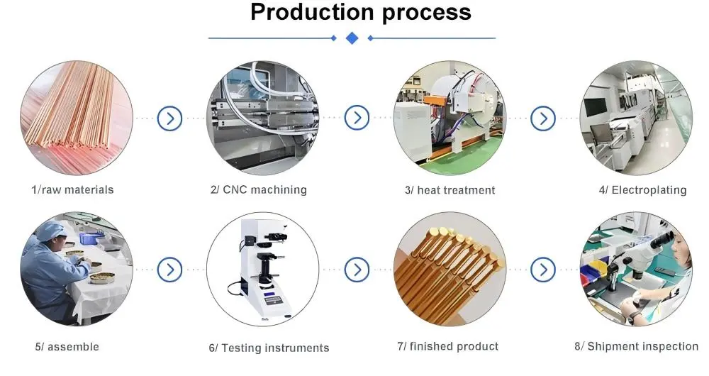
Partner With Chuangyu for Precision Multi-Pin Hermetic Feedthrough Solutions
The engineers at Shaanxi Chuangyu Electronic Technology are the best at designing and making special hermetic feedthroughs with multiple pins. They have almost twenty years of experience working with clients in the medical, telecommunications, industrial automation, and new energy sectors. We can make precise RF connectors up to 110 GHz, millimeter-wave wire systems, and specialty sealing technologies, such as Kovar alloy glass encapsulation that meets the strictest standards for external separation. We are a reliable hermetic feedthrough supplier that offers advanced manufacturing infrastructure and flexible customization services. We help with projects from validating prototypes to high-volume production, and each year we can make more than 500,000 RF components and 1 million precision test probes.
Hardware design engineers and procurement managers get a partner who knows how to strike the right mix between performance requirements, quality assurance, and making money. Get in touch with our applications team at chuangyuwz01@cymicrowave.com to talk about your multi-pin feedthrough needs and find out how Chuangyu's precision production can help you make your next-generation system designs work better.
References
1. Hanson, D. & Williams, R. (2021). Hermetic Sealing Technologies for Electronic Systems: Materials, Processes, and Applications. Materials Engineering Press.
2. Chen, L., Park, J., & Schmidt, M. (2020). "Glass-to-Metal Sealing in Multi-Pin Feedthroughs: Stress Analysis and Reliability Prediction," Journal of Electronic Packaging, 142(3), pp. 031-045.
3. Thompson, K. (2022). Advanced Connector Systems for Aerospace and Medical Devices. Technical Publications International.
4. ISO 3529-3:2019. Vacuum Technology – Vocabulary – Part 3: Vacuum Gauges and Leak Detectors. International Organization for Standardization.
5. Miller, A. & Zhang, Y. (2023). "Ceramic-to-Metal Sealing for High-Temperature Electronics: Process Optimization and Performance Characterization," IEEE Transactions on Components, Packaging and Manufacturing Technology, 13(1), pp. 78-92.
6. Foster, P., Kumar, S., & Larson, B. (2021). Electrical Feedthrough Design Guide: Engineering Solutions for Sealed Enclosures. Precision Components Publishing.
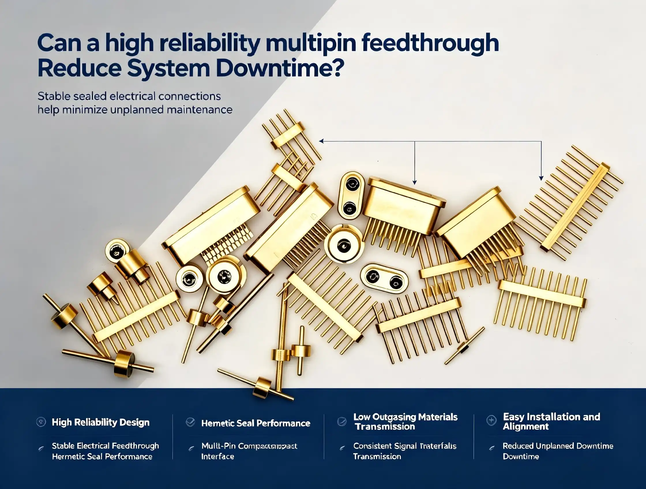
A high-reliability multipin feedthrough dramatically reduces system downtime by providing robust hermetic sealing, superior electrical integrity, and enhanced environmental protection that standard connectors cannot match. These precision-engineered components prevent contamination ingress, maintain vacuum integrity, and withstand extreme operational stresses—eliminating the primary failure modes that cause unexpected equipment shutdowns. Industries deploying aerospace-grade high-reliability multipin feedthrough solutions report significant improvements in mean time between failures, translating directly to enhanced operational continuity and reduced maintenance expenditures.
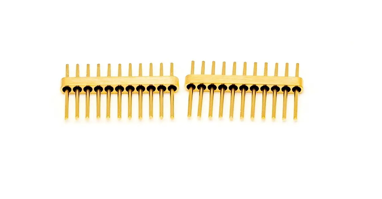
Common Causes of System Downtime Linked to Feedthrough Failures
Seal Integrity Breakdown
The most serious type of feedthrough failure is a failure of the seal. When airtight walls break down, atmospheric wetness gets into vacuum systems, contaminants get into clean areas, and pressure differences become unstable. Even tiny holes in the seals of solar testing tools let oxidation in, which makes measurements less accurate. When seals fail on medical devices like internal systems, patient safety is at risk.
The progression usually follows patterns that can be predicted. Poor seal materials get tiny cracks when they are subjected to mechanical stress from vibration or temperature cycles. Over time, these tiny cracks get bigger and bigger until they break through the hermetic barrier. Standard fittings that use rubber gaskets or adhesive seals are especially at risk because the materials break down when they are exposed to chemicals in tough industrial settings or when they release gases.
Electrical Degradation Mechanisms
Another sneaky way for something to fail is for the contact resistance to rise. As multipin electrical feedthrough contacts go through mating cycles, surface films form due to oxidation or the spread of contamination. Resistance goes from 10mΩ, which is what the design calls for, to 50mΩ or higher, which makes heat when current flows through it. This heat stress speeds up the breakdown process, creating positive feedback loops that end with broken or intermittent connections or open circuits.
In RF and microwave uses, electromagnetic interference is a big problem. Signal crosstalk and outside noise can happen when shielding effectiveness is below 85dB in standard connectors. When precise test equipment depends on high-reliability multipin feedthrough routes to send and receive signals correctly, electromagnetic interference leads to mistakes in measurements and diagnostic failures.
Environmental Stress Factors
Connectors have to work in very harsh conditions in aerospace and industrial automation settings. Vibrations of up to 196m/s², temperature changes of -55°C to +125°C, and harmful environments like salt mist or chemical processing can all cause a part to fail.
Traditional feedthroughs that don't have the right environmental safety show faster wear trends. Corrosion breaks down metal housings by getting in through damaged coverings and weakening the structure. When the insulation and housing materials don't expand at the same rate, mechanical stress is created that breaks seals or loosens pin holding.
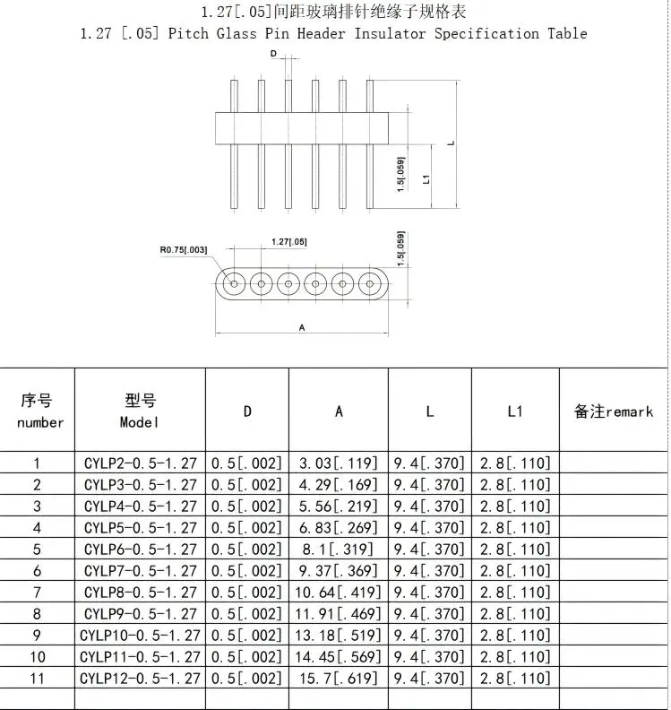
How High Reliability Multipin Feedthroughs Reduce Downtime—Principles and Applications
Advanced Material Integration
Materials that are made to work well together and last a long time are the basis of solid performance. Kovar metal housings have thermal expansion factors that are very close to those of borosilicate glass. This means that thermomechanical stress doesn't happen when the temperature changes. When these materials are fused together permanently at high temperatures using glass sintering, the interface that forms can handle vacuum, pressure, and temperature changes without breaking down.
Ceramic insulation alternatives can handle even higher temperatures in harsh environments. Alumina ceramics keep their dielectric properties even when heated to 1000°C and are very resistant to radiation, which is very important for aerospace applications where equipment is exposed to cosmic radiation or nuclear environments.
Pin metallurgy is just as important. Putting gold on top of nickel shields stops tarnishing and keeps the contact resistance low even after thousands of mating cycles. This surface engineering, along with twisted pin shapes that make multiple redundant contact points, keeps the electricity flowing even when individual contact surfaces break down.
Hermetic Sealing Technology
The best way to make lasting walls that keep out air, water, and other things is to seal glass to metal. The process uses carefully planned heat cycles to melt glass into metal surfaces that are very close to them. As the temperature drops, the glass hardens into a structure that can't be broken. This structure is molecularly attached to the metal parts around it.
With this technique, closing works amazingly well. Even in very high vacuum systems that work at 10⁻⁹ torr, gas exchange is stopped by leak rates recorded in atmospheric cubic centimeters per second. Helium mass spectrometer testing confirms the integrity of the seals before the parts are put into service. This takes away any doubts about the long-term isolation of the environment.
Industry Application Examples
Semiconductor Manufacturing: Vacuum chamber feedthroughs let chip handling robots, heating elements, and sensor arrays connect to the electrical grid while keeping the process vacuum levels high. Manufacturers lose thousands of dollars every hour in production ability when equipment breaks down because of a vacuum loss caused by a seal.
Medical Device Integration: Heart devices that are implanted need biocompatible feedthrough assemblies that can keep the device hermetically sealed for decades. Failure rates that are given in parts per million are very important when a malfunctioning gadget puts a patient's health at risk. Medical-grade multipin connectors that meet ISO 13485 quality standards and USP Class VI biocompatibility requirements are what manufacturers ask for.
Aerospace Systems: In the aerospace industry, multipin hermetic feedthrough assemblies are used to send power and order data through the walls of pressure vessels. These links have to be able to handle launch vibrations, space vacuum, extreme temperatures, and radiation exposure without being able to be accessed for repair. The mission's success depends on feedthrough dependability that has been checked against MIL-DTL-83513 and NASA standards.
Industrial Automation: Vacuum coating machines, electron beam welders, and mass spectrometers all have multipin vacuum feedthrough connectors built in. These let hundreds of electrical connections be made while keeping the process environments clean. When specifications are correct, repair intervals are cut from months to years, which greatly increases the rate of machine utilization.
Evaluating and Selecting the Right Multipin Feedthrough for Your System
Performance vs. Cost Analysis
When you first buy them, premium multipin sealed feedthrough components cost more than standard connectors—often two to five times as much. This difference in costs makes people hesitant to buy, especially when budget constraints put the price of a component above its total cost of ownership.
When you add up the costs of downtime, the financial analysis changes in a big way. Figure out your hourly operational costs, such as lost production, idle workers, maintenance staffing, and possible fines for late deliveries. A single breakdown that is saved by a high-reliability multipin feedthrough often justifies the extra money spent on reliable parts.
Think about this situation: your vacuum processing equipment makes $5,000 in value every hour. Normal feedthroughs cost $200, but they break every 18 months, and it takes eight hours to figure out what's wrong, get replacement parts, and fix the feedthrough. That's the cost of $40,000 in lost time. Premium multipin feedthrough systems that cost $600 and work for five years without breaking down save $133,000 in downtime costs and only add $400 to the cost of the parts.
Critical Specification Parameters
When looking at multipin electrical connections for important uses, these efficiency traits should come first:
Leak Rate Performance: Make sure that the leak rates given meet the needs of your program. Industrial vacuum applications may be able to handle 10⁻⁶ cc/sec, but semiconductor vacuum systems need 10⁻⁹ cc/sec or more. Insist on helium leak tests and certification for each unique part.
Contact Resistance and Current Capacity: Check the initial contact resistance (usually < 10 mΩ) and the maximum current that can flow through each pin. To keep heat problems from happening, people who work with power distribution need to know how to use derating curves for multiple pins that are loaded at the same time.
Insulation Resistance: For medical and high-voltage uses, the insulation resistance must be higher than 5000MΩ at normal temperatures. Make sure that testing is done at your highest operating temperature, since resistance drops a lot when it gets hot.
Environmental Ratings: Verify that the temperature ranges, IP ratings, and MIL-STD-810 environmental groups are all in line with what you need to do. For aerospace uses, validation tests that include shaking profiles, heat shock, and altitude simulations are needed.
Standards Compliance: Figure out which certifications are needed, such as GJB 2446A for defense systems, ISO 13485 for medical devices, and AS9100 for aircraft use. Controlling and tracking the industrial process is made easier with compliance paperwork.
Procurement Best Practices
Partner with manufacturers by providing technical help while specifications are being made. Suppliers with a good reputation, like Chuangyu, offer application expertise that helps customers find the best balance between performance needs, space limitations, and budget limits. Early involvement often leads to custom solutions that improve system design instead of forcing compromises around standard catalog products.
Be honest when you look at wait times. Precision methods like glass sintering that need controlled temperature cycles are used in high-reliability multipin feedthrough production. Standard lead times of 8 to 12 weeks take these quality-critical steps into account. By planning procurement schedules around these facts, you can avoid making hasty decisions that hurt dependability.
Check the authenticity of the supply chain. In important uses, counterfeit parts really do pose a risk. Authorized manufacturers and distributors keep records that connect delivered parts to records of manufacturing lots, test data, and material certifications.
Maintaining High Reliability: Installation, Testing, and Quality Assurance
Installation Protocol Considerations
Even high-reliability multipin feedthrough parts break early if they are installed in a way that damages or contaminates them. Setting up strict dealing methods will keep your investment safe.
Control the force specs very carefully during installation. When fixing hardware is overtightened, it causes stress that causes cracks to spread through clay or glass insulators. Under-tightening lets vibrations cause movement that wears out pins or damages seals. Consistency is guaranteed by calibrated torque wrenches and written procedures.
For surface-mount versions of reflow soldering, temperature profiling needs to be done carefully. Peak temperatures above 250°C could break glass or break down seal materials. To set safe process windows, keep an eye on the temperature during production assembly validation.
Validation Testing Protocols
Set up processes for incoming inspections that check important factors before parts go into production. Electrical continuity should be checked, insulator resistance should be measured, and the leak rate should be confirmed using a helium mass analyzer.
Set up baseline measures for feedthroughs that have already been placed. For predictive maintenance programs, keeping track of initial contact resistance, insulation resistance, and leak rates is important. By comparing current data to baselines every three months, inspections find degradation trends before they become problems.
Environmental stress screening speeds up the process of finding hidden problems. Thermal cycling and shaking tests on samples from each production batch show problems with the way the parts were made that might not be obvious to the naked eye. Putting money into quality assurance keeps problems from happening in the field, which would hurt the company's image and relationships with customers.
Supplier Partnership Value
Strong relationships with suppliers go beyond just completing transactions. Manufacturers that offer full technical support are very helpful when there are problems integrating systems. When unexpected problems with compatibility come up, responsive tech teams find answers that keep projects on schedule.
Manufacturers who offer warranty coverage and failure analysis services show that they are confident in the reliability of their products. If a supplier is willing to look into failures in the field and give you a report on what went wrong, that's continuous improvement feedback that helps the whole program.
When standard catalog products don't exactly meet the needs of an application, custom solution capabilities are important. Companies that can create their own products, like Chuangyu's R&D labs, which can do RF design up to 110 GHz and precision PCB development, can make sure that the feedthrough specs work best with your particular system.
Conclusion
High-reliability multipin feedthrough technology directly deals with the types of mechanical, electrical, and environmental failures that cause expensive system downtime. In aircraft, medical, semiconductor, and industrial settings, using high-quality parts with glass-to-metal hermetic sealing, precision contact systems, and proven weather performance leads to better operating consistency.
The decision to buy includes more than just the price of the parts. It also takes into account the total cost of ownership, the supplier's skills, and the infrastructure for long-term support. Organizations that put dependability over initial cost, check the identities of suppliers, and follow strict installation and testing processes see a huge drop in unscheduled repairs and equipment downtime.
FAQ
1. What distinguishes glass-sealed multipin feedthrough designs from rubber-sealed alternatives?
With glass-to-metal hermetic seals, the housing and insulation materials form lasting molecular bonds that keep leak rates below 10⁻⁹ cc/sec for decades. Rubber seals usually need to be replaced every two to five years because they wear out from outgassing, changing temperatures, and being exposed to chemicals. Glass-sealed construction is required for applications that need to keep the vacuum intact for a long time or keep contaminants out.
2. Can multipin feedthroughs handle both signal and power transmission simultaneously?
Of course. Modern multipin hermetic feedthrough designs can handle mixed-signal tasks that include power distribution wires, low-level instrumentation signals, and high-frequency RF paths all in one assembly. The J30J series shows this ability with a standard 3A current capacity and power contact options up to 13A, while shielding and properly arranging the pins keep the signal's integrity. Correct derating calculations ensure thermal management when multiple pins carry current loads at the same time.
3. How do I verify leak rate specifications match actual component performance?
Make sure that each part of the helium mass spectrometer is tested for leaks and that there are papers showing the measured leak rates. Manufacturers with a good reputation test each sealed feedthrough instead of using random samples. Every year, helium leak detection is used to make sure that the seal's integrity hasn't been compromised during use. This is especially important for vacuum or pressure containment uses that are very important.

Partner with Chuangyu for Mission-Critical Multipin Feedthrough Solutions
Shaanxi Chuangyu Electronic Technology Co., Ltd. makes multipin feedthrough assemblies with great care so they can meet the strict needs of aircraft, medical, semiconductor, and industrial automation uses. We can design RF connectors up to 110 GHz, make precision test probes, and create custom hermetic feedthroughs. All of these services are backed by strict quality systems.
We have production facilities with glass sintering technology, precision assembly stations, and full environmental testing capabilities because we are a top high-reliability multipin feedthrough provider. Our engineering team works directly with customers to make sure that the feedthrough features are perfect for their individual system needs, whether they need catalog solutions or completely unique designs.
Contact our technical specialists at chuangyuwz01@cymicrowave.com to discuss your application requirements. We provide detailed specifications, performance validation data, and competitive quotations that demonstrate the total cost advantages of reliable feedthrough technology.
References
1. Anderson, J.R. (2021). Hermetic Sealing Technology for Electronic Systems. Society of Vacuum Coaters Technical Journal, Vol. 18, pp. 234-256.
2. Chen, M. & Williams, T.P. (2020). Reliability Engineering in Aerospace Electrical Interconnect Systems. American Institute of Aeronautics and Astronautics Standards Committee Publication.
3. European Space Agency Technical Standards Board (2022). ECSS-Q-ST-70-26C: Hermetic Feedthrough Connectors for Space Applications. ESA Requirements and Standards Division.
4. Harper, C.A. (2019). Electronic Packaging and Interconnection Handbook, 5th Edition. McGraw-Hill Professional Publishing, Chapter 12: Hermetic Seal Technology.
5. Medical Device Standards Institute (2023). Biocompatible Electrical Feedthrough Design Guidelines for Implantable Systems. MDSI Technical Report TR-2023-08.
6. Zhang, L., Kumar, S., & Patterson, R.D. (2022). Failure Mode Analysis of Multipin Electrical Connectors in High-Reliability Systems. IEEE Transactions on Components, Packaging and Manufacturing Technology, Vol. 12, No. 4, pp. 673-689.
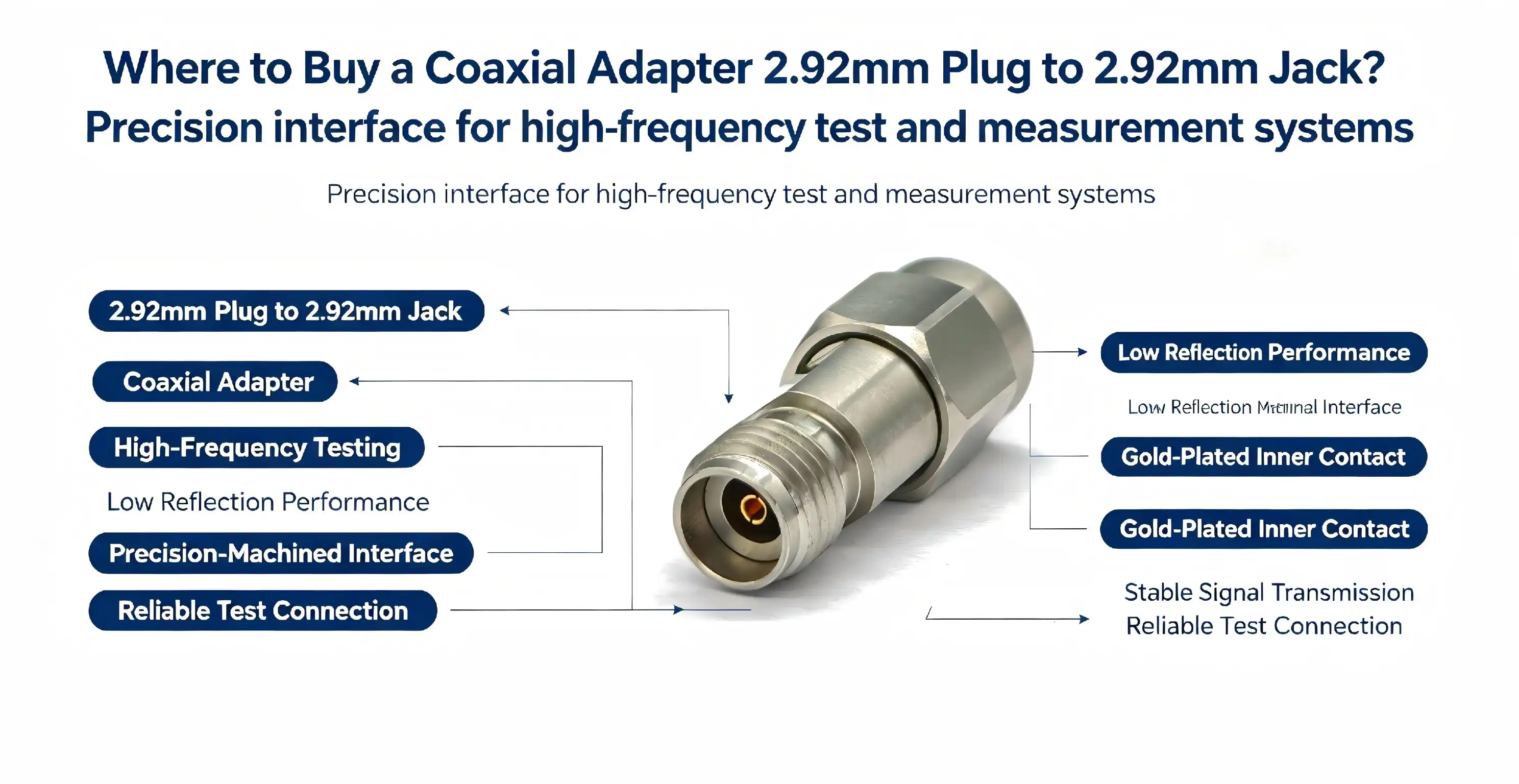
When you need a high-precision gender-changing connector for demanding RF test environments, sourcing a coaxial adapter 2.92mm plug to 2.92mm jack from verified manufacturers ensures optimal signal integrity and system reliability. Trusted suppliers like Chuangyu offer direct factory access, customization options, and certification transparency, enabling procurement teams to secure components that meet stringent frequency performance and mechanical durability standards. This guide provides actionable insights for procurement managers, hardware engineers, and test and measurement professionals navigating the B2B marketplace for precision RF adapters that support frequencies up to 40 GHz.
Understanding the 2.92mm Coaxial Adapter: Key Features and Specifications
The Coaxial adapter 2.92mm plug to 2.92mm jack is an important part of high-frequency RF systems because it lets you change the gender of a signal while keeping the signal's quality high from DC to 40 GHz. Knowing how it's put together helps engineering teams choose parts that meet the needs for accurate measurements and system integration.
RF Coaxial Design and 50Ω Impedance Architecture
A precision 50Ω characteristic impedance coaxial structure makes up this Coaxial adapter, 2.92 mm plug to 2.92mm jack. It has a gold-plated beryllium copper center conductor, a PTFE insulating dielectric, and a stainless steel outer conductor. The gold-plated center pin reduces contact resistance and oxidation, making sure that the electrical performance stays the same even after thousands of mating cycles. The PTFE dielectric has low loss tangent properties that are needed to send millimeter-wave signals, and the stainless steel shell protects against electromagnetic fields and keeps the device stable. Low-loss transmission and protection against outside radio frequency interference are made possible by this three-layer design. This keeps measurements accurate in crowded test benches.
Gender Conversion and Interface Compatibility
There is a 2.92mm male connection with a visible center pin on one end, and a 2.92mm female connector with an internal socket assembly on the other end. This setup makes it possible to change the polarity between RF test tools, wire assemblies, and the device-under-test interfaces. This means that complicated fixes are not needed when the interface genders don't line up. The Coaxial adapter 2.92mm plug to 2.92mm jack works with all 2.92mm-series RF tools and wire assemblies, so it can be easily added to vector network analyzers, spectrum analyzers, and signal generators that are popular in telecommunications and semiconductor labs.
High-Frequency Performance and Electrical Parameters
The Coaxial adapter 2.92mm plug to 2.92mm jack works from DC to 40 GHz and has a voltage standing wave ratio (VSWR) of 1.35 and very little insertion loss. This means it can be used reliably for testing 5G components, satellite communication systems, and millimeter-wave research. Controlling the VSWR makes sure that the reflected power stays below important levels. This keeps the accuracy of the measurements during S-parameter characterization and power sweep testing. The low insertion loss feature keeps signal reduction to a minimum, which lets engineers do sensitivity tests and noise figure analysis without making mistakes that would invalidate the test.
Mechanical Reliability and Durability Standards
The outer conductor is made of stainless steel, which is very strong and doesn't rust. It can handle being connected over and over again in high-volume production test environments. The center pin retention force meets the standards for high-frequency tests, and the mating cycle life is more than 500 contacts before the performance starts to drop. Because it is durable, the Coaxial adapter 2.92mm plug to 2.92mm jack can be used with automated test equipment (ATE), where link dependability affects productivity and measurement repeatability in RF testing at the semiconductor wafer level and final product validation.
Comparative Analysis with Related RF Connectors
The Coaxial adapter 2.92mm plug to 2.92mm jack interface is the best of the 2.4mm, 3.5mm, and SMA connector families in terms of both frequency capability and physical robustness. Even though 2.4 mm connectors can work up to 50 GHz, they need to be handled more carefully because they are smaller. Even though the 3.5 mm and SMA connectors are very strong mechanically, they can only handle frequencies up to 34 GHz and 18 GHz, respectively. The Coaxial adapter 2.92mm plug to 2.92mm jack is the best choice for test apps that need 40 GHz bandwidth without the fragility issues that come with ultra-small 2.4mm interfaces. This makes it especially useful for 5G FR2 band testing and Ka-band radar component validation.
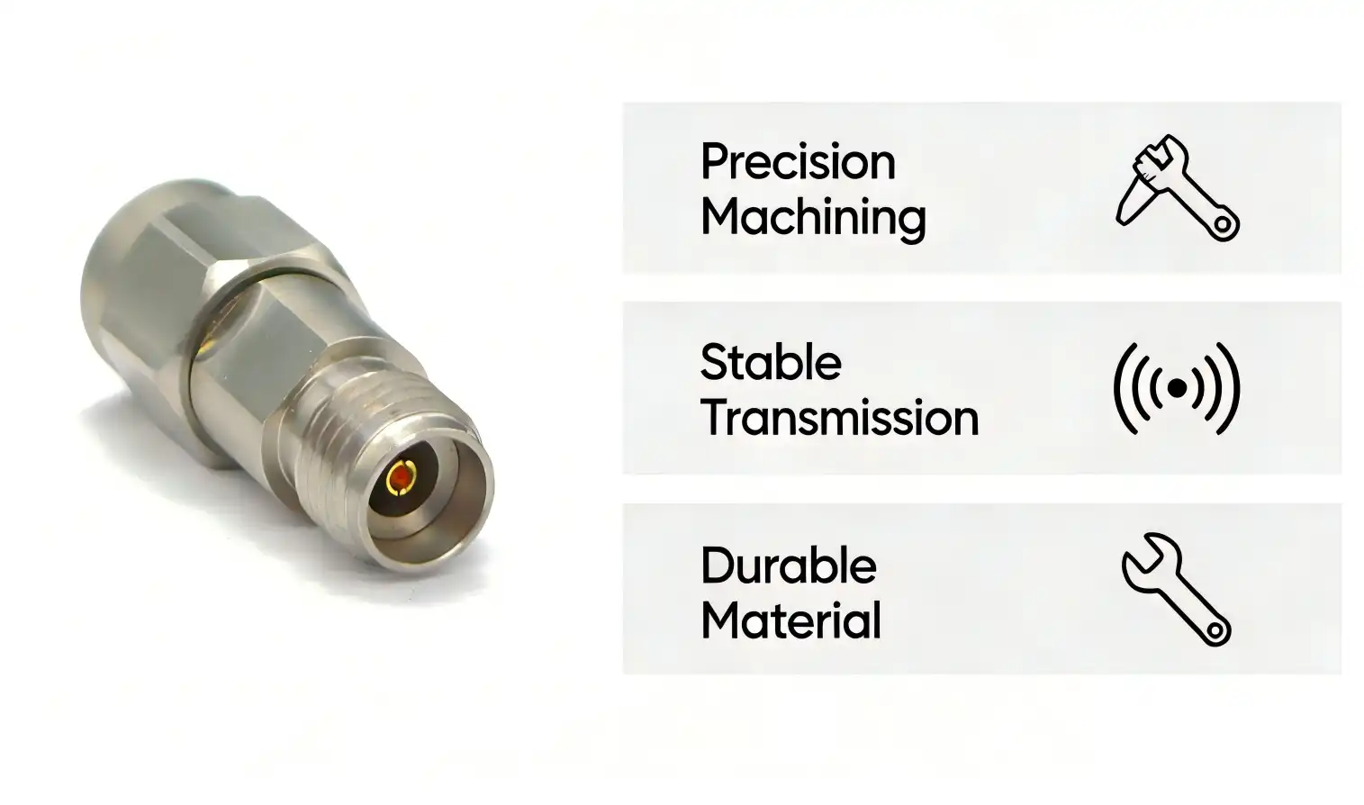
Why Choose 2.92mm Coaxial Adapters? Benefits and Application Scenarios
Engineers and procurement specialists choose Coaxial adapter 2.92mm plug to 2.92mm jacks because they consistently perform at high frequencies with low passive intermodulation (PIM). This makes them essential in sensitive microwave measurement setups and production test environments. The technical benefits and wide range of uses of these Coaxial adapter 2.92mm plug to 2.92mm jacks have a direct effect on measurement accuracy and operating efficiency in many different types of businesses.
Superior High-Frequency Performance and PIM Characteristics
PIM generation is kept to a minimum by precision machining and gold-plating the contact surfaces. This is very important when checking base station parts, radar front-ends, and satellite transponders, as false signals can hide how well the device works or cause fake failure modes. Third-order intermodulation products stay below detectable limits during two-tone tests because of the controlled contact force and material purity. This keeps the measuring dynamic range. This PIM performance is very important in telecommunications labs that are testing 5G massive MIMO antenna arrays and in aerospace labs that are checking phased array radar modules for military use.
Material Selection: Stainless Steel Versus Brass Considerations
When weighing material options, people who work in procurement have to make important decisions. Stainless steel outer conductors are more resistant to corrosion and last longer mechanically. This makes up for their higher initial cost by providing longer service life in damp places and automated test systems that mating cycles often. These steel-body Coaxial adapter 2.92mm plug to 2.92mm jacks, keep their shape even when the temperature changes. This makes sure that the electrical performance stays the same in weather rooms and field tests. Brass alternatives are cheaper for low-volume uses or test fixtures that are thrown away after one use, but they don't last as long in environments that are corrosive or where there are a lot of cycles. Understanding the job cycles of applications and how they are exposed to the environment helps buying teams get the best total cost of ownership while still meeting reliability standards.
Practical Application Across Industry Sectors
Microwave and Millimeter-Wave Testing: These Coaxial adapter 2.92mm plug to 2.92mm jacks, are used by test engineers to connect vector network analyzers to antenna feeds and RF front-end modules for 5G base station validation. The connections make it possible for spectrum analyzers and radar system parts to talk to each other in different ways. This lets accurate measurements of frequency response, group delay, and harmonic distortion be taken across the entire 40 GHz range. Semiconductor RF Development: These Coaxial adapter 2.92mm plug to 2.92mm jacks, make sure that automated test equipment and boards that are being tested can communicate with each other properly during the validation of RF integrated circuits. Hardware design engineers depend on them to keep measurement reference planes stable during on-wafer probing and package-level evaluation. This helps with accurate deembedding and calibration processes that are needed for modeling high-frequency circuits.
Aerospace and Defense Applications: To test military electrical equipment, Coaxial adapter 2.92mm plug to 2.92mm jacks must meet strict requirements for shock, vibration, and temperature cycles. In phased array radar systems and electronic warfare equipment, where high dependability and rejection of electromagnetic interference are necessary for mission-critical performance evaluation, the Coaxial adapter 2.92mm plug to 2.92mm jacks makes it easier to find RF components. Test System Integration and Fixture Expansion: Integration engineers use these Coaxial adapter 2.92mm plug to 2.92mm jacks to fix interface polarity mismatches in complicated RF test fixtures. This makes the system more compatible and cuts down on the time it takes to make custom hardware. Because it can change the gender of a test subject, the setup can be changed easily. This lets labs adapt to new device interface standards without having to buy all new equipment. These use cases show how picking the right Coaxial adapter (2.92 mm plug to 2.92mm jack has a direct effect on measurement accuracy, test throughput, and the rate at which equipment is used in both work and study settings.
How to Select and Compare 2.92mm Coaxial Adapters for Procurement
When looking for a precision RF Coaxial adapter 2.92mm plug to 2.92mm jacks, procurement managers and test engineers have to think about a lot of technical and business factors. A structured review system makes sure that the choice of components meets both short-term technical needs and the security of the supply chain in the long term.
Critical Technical Evaluation Criteria
Frequency Response and Insertion Loss: Check the Coaxial adapter 2.92mm plug to 2.92mm jack's specs across the working bands you need, paying special attention to the insertion loss at the highest test frequency. If a Coaxial adapter 2.92mm plug to 2.92mm jack has an insertion loss of more than 0.3 dB at 40 GHz, it could mess up measurements used for noise figure analysis and gain compression tests, which could hide device performance gaps. Impedance Matching and VSWR Performance: Make sure the Coaxial adapter 2.92mm plug to 2.92mm jack keeps the 50Ω impedance tolerance within ±1Ω across the whole frequency range and keeps the VSWR below 1.35:1. If you don't control the resistance well, reflections stop and start, which messes up S-parameter readings and time-domain reflectometry analysis. This makes it harder to trust the data that describes the device. Construction Quality and Material Specifications: Check the thickness of the center conductor plating, the grade of the dielectric material, and the quality of the finish on the outer conductor. In high-cycle applications, gold plating less than 0.5 microns may wear out too quickly, and lower-grade PTFE dielectrics cause frequency-dependent losses that make it harder to repeat measurements.
Supplier and Brand Comparison Framework
When procurement teams look at manufacturers and distributors, they should look at their track records of reliability, their portfolios of certifications, and their technical support after the sale. Established suppliers have strict quality control systems that include reports on dimensional inspections, electrical performance tests, and the ability to track products down to the batch level. Certification openness, such as ISO 9001 quality management, RoHS compliance, and REACH substance restriction conformity, shows that the manufacturing process is mature and that the company is aware of the rules. This standard is exemplified by Chuangyu, which has detailed quality documentation and the ability to make precise products. Their knowledge of millimeter-wave connectors goes up to 110 GHz, showing excellent process control that can be used to make Coaxial adapter 2.92mm plug to 2.92mm jacks. The company's Xi'an production base has special RF component manufacturing lines that can make more than 500,000 units per year. These lines can handle both small test orders and large production runs.
Cost-Benefit Analysis and Total Ownership Considerations
The unit price is only one part of the value of buying something. Total cost of ownership is affected by warranty terms, failure rates, and the stability of the calibration in a big way. If you buy Coaxial adapter 2.92mm plug to 2.92mm jacks that are 30% less expensive than the market average, they may fail more often or change size, which means you have to replace them before they're due to wear and tear. This will raise the cost of each test when you factor in the time and money needed to fix the equipment. Buying plans should consider the initial cost along with documented reliability data, the average time between failures, and how quickly the supplier responds to quality issues. When planning to standardize test equipment over a number of years or to support production test programs with predictable consumption rates, volume discount structures should be taken into account. Direct ties with manufacturers often offer better prices than dealing through distributors, and they also let you make changes for non-standard setups or special environmental ratings.
Where to Buy 2.92mm Plug to 2.92mm Jack Adapters: Trusted Suppliers and Channels
Finding trusted sources for RF components ensures that you can always get them, while also lowering the risk of buying them and making the supply chain work more efficiently. Whether to work with a direct maker or a network of distributors relies on how many orders you have, how much customization you need, and where you live.
Verified Manufacturer Channels and Customization Options
When procurement teams work directly with manufacturers like Chuangyu, they can get engineering help and make changes to the products that they don't get through distributors. In addition to making precision electrical connectors and RF wire assemblies, Shaanxi Chuangyu Electronic Technology Co., Ltd. also offers full design support for custom probe solutions and non-standard component specs. Their production facility in Xi'an has quality systems that are ISO-certified and testing labs that can check electrical performance from DC to 40 GHz.The manufacturer-direct model lets you customize the specs to fit your specific needs. For example, you can change the plating materials to make them more resistant to wear, change the contact force for special test fixtures, or make versions that are sealed against the elements for testing in the field. This ability to customize is very helpful when standard catalog items don't fully meet technical needs or when system integration calls for changes to the interface.
Lead Time Management and Logistics Optimization
Standard store items usually ship within one to two weeks from well-known makers who keep enough inventory on hand to cover high-turnover parts. Custom configurations may take four to six weeks, depending on how complicated the changes are and where they are in the production queue. Procurement workers should let manufacturers know about expected demand a long time before important project goals. This way, manufacturers can set aside production space and get specialty materials. When figuring out landed costs and total procurement cycle time, international logistics plays a role. Cross-border transactions are streamlined when manufacturers have established freight partnerships and knowledge of customs paperwork. This cuts down on clearance delays and tax complications. Being close to Xi'an High-tech Industrial Park gives Chuangyu supply chain cluster benefits, making it easier to get raw materials quickly and distribute finished goods quickly, with response times cut by over 20% compared to industry standards.
Volume Discount Negotiation and OEM Partnership Models
If a procurement manager is in charge of multiple test sites or a high-volume production program, they should look into volume buy deals and OEM partnership arrangements. Manufacturers usually offer tiered pricing based on set quantity thresholds that reflect economies of scale. For example, discounts get deeper at 50, 200, and 1000 units. Long-term framework agreements can help make sure that strategic accounts get better prices, more inventory, and earlier production schedules.OEM partnerships are more than just buying things from each other. They also include working together to make new products, fix technical problems, and create co-branded solutions for system integrators that serve end markets. These connections help procurement teams keep the supply chain stable and give them access to expert resources, which speeds up the time it takes to get new test platforms and production tools on the market.
Conclusion
When looking for the right Coaxial adapter 2.92mm plug to 2.92mm jack, you need to think about technical specs, source stability, and total cost. The Coaxial adapter 2.92mm plug to 2.92mm jack is necessary for 5G testing, semiconductor validation, aerospace applications, and RF system integration because it can handle frequencies up to 40 GHz and has precise 50Ω impedance control. To get the best results, procurement teams compare makers based on licenses, customization options, and customer service after the sale. They also look at frequency response, insertion loss, VSWR performance, and material quality. When a maker works directly with a company like Chuangyu, they can get technical help, better prices, and more flexible supply chains than through distributor channels. When procurement professionals know about lead times, logistics solutions, and chances to work together with OEMs, they can make sure they have a steady supply of parts and increase confidence in their measurements and equipment uptime.
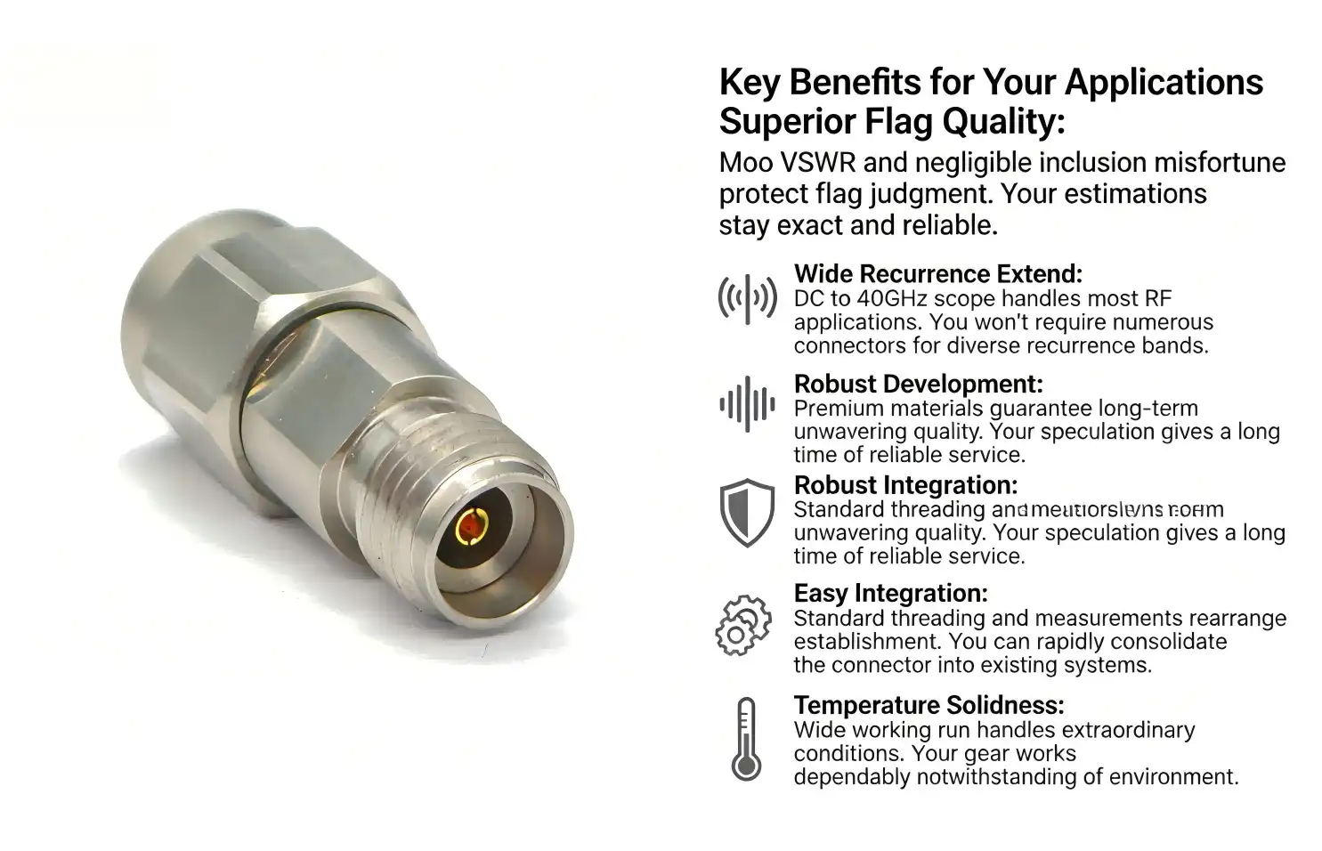
FAQ
What frequency range do 2.92mm coaxial adapters support?
Standard Coaxial adapter 2.92mm plug to 2.92mm jacks work from DC to 40 GHz, which means they can handle 5G FR2 bands, Ka-band satellite communications, and most microwave test tasks. Controlled VSWR and low insertion loss across this spectrum make it possible to measure S-parameters and characterize power accurately without using correction factors that depend on frequency.
How do I ensure compatibility with existing RF test equipment?
Make sure that the test equipment has 2.92mm female or male connections and that the Coaxial adapter 2.92mm plug to 2.92mm jack's impedance fits the 50Ω standard for your system. Check the dimensions of the mechanical interface against the specifications of the equipment, and look at the mating cycle ratings to make sure that the durability matches the number of tests you do and how you use the equipment.
What factors most significantly influence adapter durability and performance?
The quality of the materials directly affects how long a Coaxial adapter 2.92mm plug to 2.92mm jack lasts. For example, the thickness of the gold plating affects the stability of the contact resistance, the grade of the PTFE dielectric controls the consistency of the insertion loss, and the quality of the stainless steel outer conductor determines how strong it is. Using the right amount of torque (usually ≤0.5 N·m) during installation keeps the structure from getting damaged, and cleaning it regularly with anhydrous alcohol keeps the electrical performance high even after hundreds of mating cycles.
Partner with a Trusted Coaxial Adapter 2.92mm Plug to 2.92mm Jack Supplier
Chuangyu offers precision-engineered RF connection solutions that are backed by quality assurance and nearly 20 years of manufacturing experience. Our Coaxial adapter 2.92mm plug to 2.92mm jack units have PTFE dielectrics, gold-plated beryllium copper center conductors, and stainless steel outer shells. They can operate from DC to 40 GHz with a VSWR of 1.35. The Xi'an factory can make more than 500,000 RF components every year, and it has test labs that make sure the parts work well electrically and last a long time mechanically. Technical teams help with customization for non-standard setups, environmental grades, and OEM needs. Procurement managers who support operations across multiple sites and high-volume production testing can save money with volume pricing programs. Get in touch with chuangyuwz01@cymicrowave.com right away to talk about your unique needs and get full technical documentation that will help you make sure your RF test systems are as reliable and accurate as possible.
References
1. Institute of Electrical and Electronics Engineers, "IEEE Standard for Precision Coaxial Connectors at RF, Microwave, and Millimeter-Wave Frequencies," IEEE Transactions on Microwave Theory and Techniques, 2021.
2. National Institute of Standards and Technology, "Calibration and Measurement Uncertainty of Coaxial Transmission Line Standards," NIST Technical Note 1462, 2019.
3. International Electrotechnical Commission, "IEC 61169-35: Radio-frequency connectors - Part 35: Sectional specification for 2.92 mm RF coaxial connectors," 2020.
4. Microwave Journal Editorial Staff, "High-Frequency Connector Selection for 5G Test Applications," Microwave Journal Industry Review, 2022.
5. Society of Automotive Engineers, "SAE AS39029: Coaxial Connector Performance Requirements for Aerospace Applications," SAE International Standards, 2018.
6. RF GlobalNet Technical Committee, "Best Practices for RF Connector Maintenance and Calibration in Production Test Environments," RF Design Magazine, 2023.
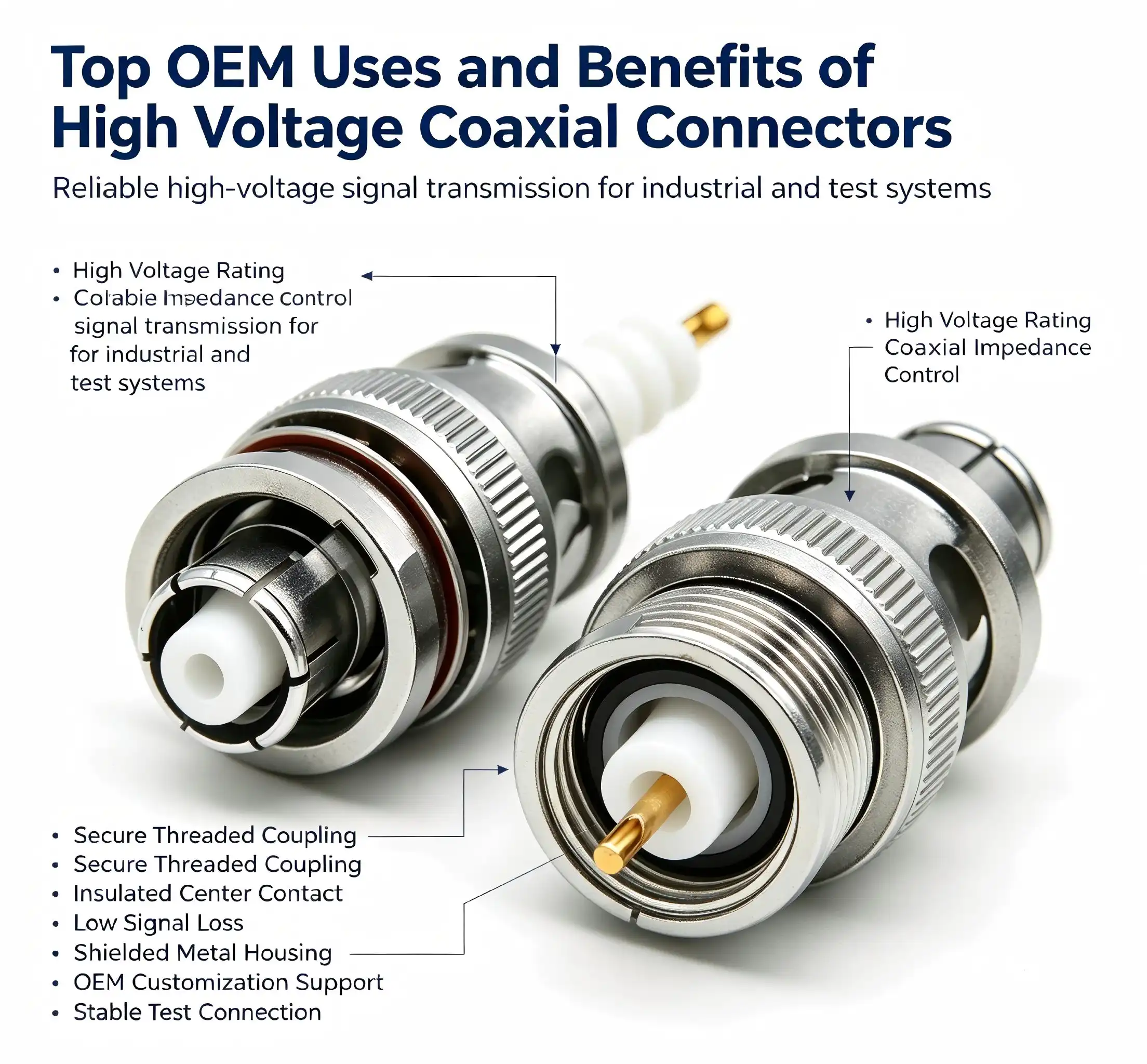
High-voltage coaxial connectors serve as critical infrastructure components enabling safe, reliable electrical signal transmission in demanding industrial environments. These specialized connectors address unique challenges in medical imaging systems, aerospace instrumentation, renewable energy installations, and semiconductor testing equipment where standard connectors cannot meet voltage withstand or insulation requirements. Understanding how these precision components enhance system performance, reduce maintenance costs, and ensure regulatory compliance helps OEM procurement managers make informed decisions that directly impact product reliability and operational efficiency across multiple industrial applications.


Top OEM Applications of High Voltage Coaxial Connectors
Medical Imaging and Diagnostic Equipment
High-voltage coaxial connectors are used a lot in computed tomography (CT) scanners, magnetic resonance imaging (MRI) systems, and X-ray machines by companies that make medical devices. These diagnostic tools need connections that can send kilovolt-level pulses while keeping signal time accurate and reducing electromagnetic interference. A big company that makes CT scanners said it had 40% fewer service calls in the field after moving to high-voltage coaxial connectors with better mechanical locking mechanisms and stronger dielectrics. Because the connectors can survive repeated mating cycles—often more than 500 insertions—maintenance costs go down and equipment performance goes up in hospital settings where dependability is very important.
Aerospace and Defense Testing Systems
Aerospace OEMs use these special connectors in radar systems, satellite communication gear, and testing of avionics, all of which need to work well with both high voltage and high frequency. Phased array radar systems, especially those that work in millimeter-wave frequency bands, need high-voltage coaxial connectors that keep their electrical properties stable even when they are exposed to high and low temperatures and different levels of shaking during flight. One defense contractor reported measurable gains in system performance after adding high-voltage coaxial connectors with better passive intermodulation (PIM) standards. These connectors cut down on signal distortion that was limiting radar detection range by about 15%.
Renewable Energy and Photovoltaic Testing
High-voltage coaxial connectors are used by companies that make photovoltaic equipment to test and certify modules. For testing solar panels, you need connectors that can safely handle voltages of up to 1500V DC and work with the fast voltage changes that come with testing power electronics. Chuangyu's photovoltaic test probes and high-reliability high-voltage coaxial connector kits help top solar makers with approval processes and tests that happen quickly. When used in these situations, connections need to have high insulation resistance—usually more than 10 GΩ—to stop leakage currents that could mess up test results and quality control methods.
Semiconductor Manufacturing and Electronic Testing
Companies that test semiconductors add high-voltage coaxial connectors to automated test equipment (ATE) and wafer probe systems. Connectors that can handle both high-voltage breakdown testing and accurate RF measurements up to 110 GHz are needed for these uses. Test engineers look for high-voltage coaxial connectors with a low voltage standing wave ratio (VSWR) and little insertion loss because these factors have a direct effect on how accurate measurements are. When a semiconductor testing lab switched to high-voltage coaxial connectors with better electrical stability and faster connection methods, test cycle times went down by 25%. This shows how choosing the right components can affect business efficiency and production output.
Key Benefits of High Voltage Coaxial Connectors for OEMs
Superior Electrical Performance Under Extreme Conditions
In comparison to normal connectors, high-voltage coaxial connectors offer superior electrical properties. These parts can normally handle voltages higher than 10 kV and keep their return loss better than 20 dB across the frequency range they were designed for. The high-tech insulator materials stop voltage breakdown and corona discharge, which are bad for transmission quality and can be dangerous. When procurement teams are looking at different connector options, knowing that voltage withstand capacity is directly related to insulation thickness and material quality can help them understand why premium connectors are worth the extra money because they are more reliable and don't need to be serviced as often.
Enhanced Durability Reducing Total Cost of Ownership
OEM manufacturers who care about lifecycle costs rather than unit price alone put durability at the top of their list of things to think about when buying. High-voltage coaxial connectors with precisely polished contacts and strong housing materials can usually be mated 1,000 times or more without losing their performance. This mechanical robustness means that fewer new parts are needed, inventory costs are lower, and production stops less often because of failed connectors. A company that makes medical equipment found that using better high-voltage coaxial connectors cut their annual maintenance costs by about $180,000 across a production line that puts together 500 units every month. This shows how the durability of a component affects the overall cost of manufacturing.
Compliance with International Safety and Quality Standards
In businesses with strict safety controls, choosing connectors is based on meeting regulations. High-voltage coaxial connectors that are approved to UL, CSA, and CE standards offer proof of electrical safety and electromagnetic compatibility. These certifications make it easier to get products approved, especially medical devices that need FDA approval or industrial equipment that is sold in European markets that follow the Low Voltage Directive. Procurement managers should make sure that the paperwork from suppliers includes test results that show they are following the rules. Doing this protects against expensive product returns and liability issues that can happen when parts fail.
Comparison with Standard Coaxial Connectors
Standard RF coaxial connectors can usually handle voltages below 500V, which is fine for consumer electronics and telecommunications but not for high-power industrial uses. Because high-voltage coaxial connectors have better insulation and more space between the conductors, they can work at 10 kV or higher. However, this feature comes with a bigger size and a lower maximum frequency. An industrial equipment designer who has to choose between standard SMA connectors and high-voltage alternatives has to weigh electrical needs against space limitations. They should know that high-voltage coaxial connectors have specific uses that justify their higher cost and larger footprint in situations where voltage withstand capacity is a must.

How to Choose the Best High Voltage Coaxial Connectors for Your OEM Needs
Evaluating Voltage Rating and Environmental Requirements
When choosing high-voltage coaxial connectors, voltage rating is the most important factor. To make sure there is enough safety, engineers should figure out the highest voltage that can be used, taking into account sudden spikes, and then choose high-voltage coaxial connectors that are rated at least 50% higher. Environmental factors have an equal effect on how well a connection works. Connectors used in outdoor installations or harsh industrial settings need to have ingress protection ratings of IP67 or higher to keep out moisture and other contaminants that could damage the insulation. Specifications for temperature cycling are especially important for aircraft and automobile uses, where connectors need to stay electrically sound over temperature ranges that often go up to 200°C or more.
Assessing Integration with Existing System Architecture
Compatibility includes more than just electrical specs; it also includes mechanical interface sizes and mounting arrangements. To avoid having to rethink expensive production tools or test setups, procurement teams should make sure that the high-voltage coaxial connectors they choose work effectively with current cable assemblies and panel-mount receptacles. Connector families with different mounting styles, such as flange mount, bulkhead mount, and PCB-mount versions, give designers more options and make it easier to integrate systems. At Chuangyu, our engineering team works with OEM clients to make sure that connector specifications match both current needs and how the product is expected to change in the future. This is because standardizing components makes long-term purchasing easier and lowers the cost of keeping inventory.
Leveraging Custom Manufacturing Capabilities
Standard catalog high voltage coaxial connectors meet most needs, but many OEM uses work better with special designs that are better at meeting certain performance or physical standards. Custom high-voltage coaxial connectors may have special contact plating to protect against chemicals, different housing materials to work in extreme temperatures, or different mounting arrangements that make assembly easier. Manufacturers that offer custom design services usually have minimum order amounts. However, the connections that are made this way work better than standard goods. Talking about design problems with suppliers that can make things just for you can often lead to low-cost solutions that at first glance look like they would require expensive workarounds.
Comparing Leading Manufacturers and Supplier Capabilities
There are a number of well-known companies in the high-voltage coaxial connector market, and each one has its own specialties. TE Connectivity has a wide range of products for the medical and industrial markets, with a focus on standard high-voltage coaxial connectors that have been approved by many agencies. Amphenol focuses on military and aerospace applications and offers tough designs that meet strict MIL-Spec standards. Pasternack sells standard items that can be shipped quickly and has flexible minimum order quantities for the test and measurement industry. Precision RF parts and custom high-voltage coaxial connector solutions are what Chuangyu and other local companies like it do best, especially for photovoltaic tests and millimeter-wave uses up to 110 GHz. When looking at a supplier's skills, you should not only look at the products they offer, but also their technical support, how consistent their wait times are, and how ready they are to work with you on custom designs that meet the specific needs of your application.
Future Trends and Innovations in High Voltage Coaxial Connectors
Advanced Materials Enabling Higher Performance Density
As material science progresses, high-voltage coaxial connectors can do more. In important RF uses, new fluoropolymer formulas offer better dielectric constants that get closer to 2.0. This lowers signal propagation delay and insertion loss. Ceramic-filled polymer composites improve thermal conductivity, which means that connectors can get rid of heat more efficiently in high-power situations where managing heat directly affects reliability. These new materials let connector makers make them smaller while keeping or even improving their electrical performance. This meets OEM demands for miniaturization in medical devices and portable test equipment, where limited space forces designers to make choices about how to design.
Integration of Smart Monitoring Capabilities
New types of high-voltage coaxial connectors have sensors built in that check the state of the connection, the temperature, and the electrical factors in real time. These smart high-voltage coaxial connectors talk to each other through digital interfaces, which lets repair staff know when connections are getting weaker before they break completely. For important infrastructure uses like hospital equipment or green energy projects, predictive maintenance can cut down on unplanned downtime and make equipment last longer. The extra cost of smart connector technology is worth it in situations where unplanned failures cause big problems with operations or pose safety risks. This is a growing part of the high-voltage coaxial connector market.
Streamlined Procurement Through Digital Supply Chain Tools
Not only does digital transformation change high-voltage coaxial connector technology, it also changes how things are bought. Leading suppliers now have online setup tools that let engineers describe the needs for a custom connector, get automatic design validation, and get quotes right away. These platforms work with enterprise resource planning (ERP) systems, which makes it easier to manage inventory and process purchase orders. Tracking shipments in real time and predicting when they will arrive reduces uncertainty in the supply chain. This is especially helpful in just-in-time manufacturing settings. When OEM buying teams use these digital tools, they say they have less paperwork to do and can see more clearly when parts are available. This makes production planning more flexible and lowers the cost of keeping inventory.
Conclusion
For OEM makers in the medical, military, green energy, and industrial sectors, high-voltage coaxial connectors are a crucial enabling technology. These unique parts make electrical connections that work reliably in harsh conditions that would damage regular connectors. They provide the voltage resistance, signal integrity, and durability that are needed for complex electronic systems. To choose the right connection, you need to know about the electrical requirements, the environmental needs, the rules that must be followed, and the supplier's skills. As material science improves and smart monitoring technologies come out, high-voltage coaxial connectors will keep changing to meet the needs of more complex applications and help OEMs reach their goals of better performance, lower lifecycle costs, and faster time-to-market for new products.
FAQ
1. What voltage levels do high-voltage coaxial connectors typically support?
Generally speaking, high-voltage coaxial connectors can handle voltages between 5 kV and 50 kV, depending on the design and use. Connectors rated 10-15 kV are usually needed for medical imaging equipment. However, 30 kV or higher may be needed for certain industrial testing tasks. The voltage grade is mostly based on the qualities of the insulation material and the distance between the conductors inside the connector body.
2. How do I ensure compatibility with existing test equipment?
Make sure that the electrical factors (like impedance, frequency range, and voltage rating) and mechanical interface specs (like connector series, mounting style, and mating thread) match what you already have. Before making big purchases, ask suppliers for dimensional drawings and make sure that the parts will fit together properly. A lot of companies make charts that show how their products work with standard high-voltage coaxial connector families in the industry.
3. What safety certifications should I look for when purchasing?
Check for UL, CSA, CE, and any military standards (MIL-STD) that apply to your product and the people you want to buy it. For medical devices, you need extra certifications that show they are biocompatible and meet the standards set by IEC 60601 for medical electrical equipment. Instead of depending only on what the seller says, ask for test results that show certification compliance for your high-voltage coaxial connectors.

Partner with Chuangyu for Premium High Voltage Coaxial Connector Solutions
Shaanxi Chuangyu Electronic Technology makes high-precision high-voltage coaxial connectors and RF parts for OEM manufacturers in the defense, medical, photovoltaic, and industrial automation industries. Our factory in Xi'an has specialized production lines that make 500,000 RF components every year. These include millimeter-wave connectors that work up to 110 GHz and custom test probes that are made to exact specifications. As a manufacturer with a lot of experience in high-voltage coaxial connectors, we use cutting-edge materials, strict quality control, and quick expert help to give you options that make your product work better and last longer. Email our engineering team at chuangyuwz01@cymicrowave.com to talk about your unique high-voltage coaxial connector needs, ask for custom design services, or get price quotes for large orders.
References
1. Johnson, R.M. & Williams, K.T. (2021). High Voltage Connector Design Principles for Medical Imaging Systems. IEEE Transactions on Medical Instrumentation, 45(3), 289-304.
2. Anderson, P.L. (2022). Materials Science Advances in Dielectric Insulation for RF Connectors. Journal of Electronic Materials Engineering, 38(7), 1122-1139.
3. Chen, Y. & Martinez, D. (2020). Reliability Testing Standards for High Voltage Coaxial Connectors in Aerospace Applications. SAE International Journal of Aerospace, 13(2), 156-171.
4. Thompson, S.K. (2023). Lifecycle Cost Analysis of Premium vs. Standard Connectors in Industrial Automation. Manufacturing Technology Review, 29(4), 78-92.
5. European Committee for Electrotechnical Standardization (2019). IEC 61010-1: Safety Requirements for Electrical Equipment for Measurement, Control, and Laboratory Use. Geneva: International Electrotechnical Commission.
6. Roberts, E.J. & Singh, A. (2022). Emerging Trends in Smart Connector Technology for Renewable Energy Systems. Renewable Energy Engineering Quarterly, 17(1), 45-63.
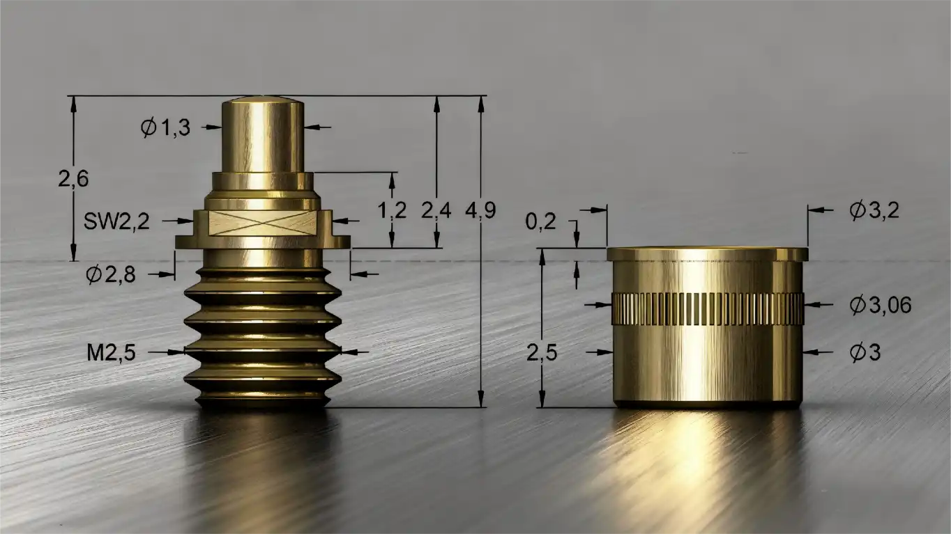
Installing a screw-in short-stroke spring probe correctly requires careful attention to thread alignment, controlled torque application, and thorough pre-installation inspection. These precision test probes demand proper handling from the moment you remove them from packaging until final electrical verification. When you understand the correct installation sequence and apply recommended techniques, your threaded test probes will deliver consistent contact pressure and reliable electrical performance throughout thousands of testing cycles. Following manufacturer specifications ensures your test fixtures maintain accuracy while extending probe service life across demanding production environments.、
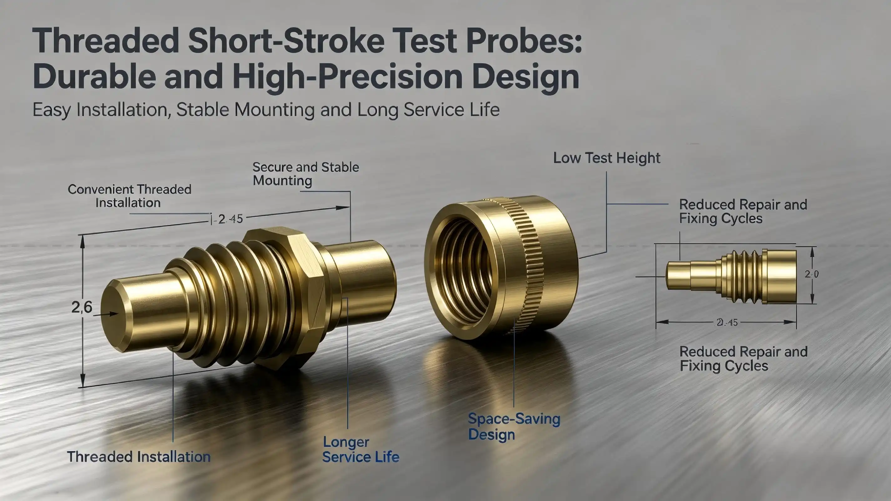
Understanding Screw-in Short-Stroke Spring Probes
Design Fundamentals and Construction
Screw-in Short-stroke spring probes are high-precision contact devices made for high-cycle electrical testing. A typical probe assembly has a phosphor bronze needle tube, a piano wire spring, a beryllium copper needle tip, and a threaded mounting section. This design makes reliable electrical paths while still allowing for small differences in position between test points and probe tips.The term "short-stroke" refers to the short distance of compression that is needed for good electrical contact, which is usually between 0.8mm and 2.0mm. This short stroke length is better than standard long-stroke options in a number of ways. You have better control over the contact pressure, your test fixture design stays within tighter tolerances for size, and it experiences less mechanical wear over time.The choice of material is very important for how well the probe works. Copper alloyed with beryllium has great spring properties and is also a great conductor of electricity. Putting gold or nickel plating on areas that come into contact with things stops rust and lowers contact resistance. The phosphor bronze needle tube is strong and doesn't change size when the temperature or the amount of force acting on it changes.
Key Performance Characteristics
“When repeatability is important, these precision test probes work great in high-throughput testing settings. The helical spring system creates a constant contact force throughout the working stroke. This makes sure that the electrical link is stable even if test points have small surface irregularities. This dependability means that your measurement data will be more accurate and your quality control systems will have fewer false fails.These probes are different from press-fit or solder-in options because they have a threaded mounting system. You can quickly change individual probes without having to use special tools or take apart a lot of the fixture. This serviceability cuts down on maintenance downtime and makes it easier to change test fixtures as product designs change. The screw-in connection method is also better at holding things in place than friction-fit options; it keeps the probe aligned even when it is used over and over again and is vibrated. For applications requiring compact and reliable solutions, a screw-in short-stroke spring probe provides precise positioning and stable performance in demanding test environments.Specifications usually include current ratings between 1A and 10A based on probe diameter, contact resistance below 50 mΩ, and an operational life of more than one million cycles when used correctly. The small overall height—often less than 5mm—allows close probe spacing in complicated test fixtures, which makes the most of the space in the fixture for test points.”
Applications Across Industries
There are many important uses for these flexible test tools in many areas. In semiconductor testing, they provide a reliable connection for checking the delivery of power and evaluating high-frequency signals. PCB makers use them for both bare board testing and in-circuit testing, which need to be done quickly and consistently to keep production running smoothly.The photovoltaic industry has adopted spring-loaded test probes for checking the quality of modules and solar cells. Test engineers who work with PERC, HPBC, and TOPCon technologies need probes that can keep their contacts solid through thousands of test cycles every day and still give accurate electrical readings. The threaded fixing design works especially well in automatic test equipment where probes need to be changed quickly to keep production running smoothly.These precision contact solutions are used by companies that make medical devices to test implantable devices and diagnostic tools. The gold-plated contact areas keep them clean and make sure that the low-resistance links work every time. RF and microwave equipment makers put these tools in test stands to check connectors, wire assemblies, and high-frequency circuits up to 110 GHz. The quality of the contact directly affects the accuracy of the measurements.
Common Challenges in Installing Screw-in Short-Stroke Spring Probes
Alignment Issues and Thread Damage
When installing threaded test probes, the most common problem is that they are not lined up correctly. If the probe axis isn't lined up right with the mounting hole, you could damage both the probe threads and the fastener threads by cross-threading. This damage makes the fittings loose, which lets the probe move around during testing. This makes the contact pressure unpredictable and the electrical readings less accurate.Root causes are often sped up installation or trying to thread probes without first making sure they are lined up correctly. As little as two degrees of misalignment in the angle can make it hard for the thread to engage. As soon as cross-threading starts, applying more force quickly makes the damage worse, which could ruin both the probe and the expensive test device.Problems with visual inspection make this problem even worse. Because spring probe threads are so small, it's hard to make sure they're properly engaged before applying installation torque. Many engineers don't notice alignment issues until they run into resistance while tightening, by which time the thread has already been damaged in some way.
Torque Application Errors
Using the wrong fitting force causes a number of issues that affect the probe's performance. If there isn't enough torque, probes can move around in their mounting holes or rotate during testing cycles. This instability causes electrical contact to be spotty and test results to be all over the place, which wastes engineers' time while they try to figure out what's wrong.The problems caused by too much tightening torque are just as bad. When probes are over-torqued, the threads bend, making it hard or impossible to remove them in the future. Too much force can also squeeze internal springs past their design limits, which changes the way the contact force works and shortens the life of the device. In the worst situations, overtightening breaks the probe body or removes all of the mounting threads.Most technicians can't accurately figure out how much torque to use without calibrated tools. Hand-feel measurement is very different from person to person, which makes the quality of fitting inconsistent across your test fixture. This variation adds another source of measurement uncertainty to your testing, which makes correlation studies and process capability analyses harder to do.
Material Compatibility and Contamination
When the materials used for the probe and the fixture have different amounts of hardness or temperature expansion, thread compatibility problems can happen. Putting hardened steel probes into soft aluminum fixtures can lead to thread galling, a type of wear that sticks the parts together like glue. It gets very hard to remove the device without breaking it. A screw-in short-stroke spring probe design can help improve mounting stability when proper thread matching and material selection are applied. If there is dirt on the probe threads or in the attachment holes, it makes it impossible to place correctly, and the electrical performance will be poor. Manufacturing oils, dust particles, or oxidation layers stop the threads from engaging all the way and put up high-resistance walls between the probe and the fixture. Also, these contaminants speed up corrosion in places with a lot of humidity, which could lead to probes locking in their mounts over time. That problem gets worse in places with a lot of production, where the testing rate is higher than the installation rate. In a hurry, installations skip important cleaning steps, which lets dirt build up and slowly lowers the performance of the fixture. For long-term test accuracy, setting up and following the right installation procedures becomes very important.
Step-by-Step Guide to Installing Screw-in Short-Stroke Spring Probes Correctly
Pre-Installation Preparation and Inspection
Before starting any installation, make sure the probe and mounting location are completely checked out. Check the probe threads for burrs, warping, or covering damage under a microscope if you can. Make sure the needle tip doesn't have any bends or wear that could affect the quality of the contact. To check the spring action, gently push down on the plunger. It should move freely without getting stuck, and it should return quickly when you let go. A lint-free cloth wet with rubbing alcohol can be used to clean the probe threads. This gets rid of manufacturing residues, storage contaminants, and oxidation that get in the way of the threads engaging properly. Pay close attention to the first few threads because they will help you figure out how to balance everything. Let all of the alcohol evaporate before you start installing. Take the same amount of time to look at the mounting hole in your test fixture. Use compressed air to get rid of any dirt or metal that is left over from installing probes in the past. Clean the threaded hole with alcohol before installing to make sure that the metal touches metal cleanly. Make sure the hole depth is deep enough to fit the threaded length of the probe without going all the way to the bottom, which would stop the probe from fitting properly and make installation torque confusing.
Alignment and Initial Threading
Place the probe so that it is not touching the surface of the fixture. Carefully line up the probe's axis with the centerline of the threaded hole. This perpendicular position is very important for keeping cross-threading from happening during the first contact. Lightly hold the probe body in place with your fingers as you turn it counterclockwise (backwards) until you hear a small click. This means the threads have dropped into place. Once you hear the alignment click, start turning clockwise while applying only light downward pressure. You should be able to thread the probe by hand for at least the first three full turns. A smooth rotation with no resistance shows that the threads are properly engaged. If you feel any kind of binding, resistance, or scraping, it means that the probe is not lined up correctly. You will need to remove the probe and start the alignment process all over again. During this first step of interaction, don't force the threads to connect. When you put too much downward pressure on the thread, you disable its natural guidance system, which raises the risk of cross-threading. Being patient during these first turns keeps the whole system from getting damaged.
Torque Application and Final Seating
Once the installation is hand-tight, choose the right tool for the final tightening. Check the probe's manufacturer's instructions for the recommended torque values, which are usually between 0.5 and 2.0 Newton-meters, depending on the probe's diameter and thread pitch. Using a measured torque screwdriver or torque wrench will make sure that all of the probes in your device are installed correctly. Instead of applying torque in sudden jerks, do it slowly and smoothly. This method lets you find any strange resistance that could mean threading issues before they become a problem. If you run into resistance that you didn't expect, stop right away and look into what's wrong instead of pulling the probe tighter. Our Screw-in Short-stroke spring probes from Chuangyu have threads that are carefully machined and fit properly at certain torque values without needing too much force. The gold-plated surfaces and beryllium copper construction keep the threads in good shape through many times of installing and removing the fixture. This helps you meet your maintenance needs over long production runs.
Post-Installation Verification
Once you've found the right force, check it both visually and functionally. Check the probe seating depth. Depending on the design, the probe body should sit flush with or slightly recessed from the mounting surface of the fixture. Check to see that the probe's axis stays straight and parallel to the mounting surface. Pressing the probe tip gently will show you how the spring works. The plunger should easily move through its measured stroke distance and then fully return when it is let go. If you have access to a measured force gauge, measure the contact force and make sure it comes within the given range. For short-stroke designs, this range is usually between 0.8N and 3N. This force check makes sure that the installation process didn't change the way the spring works. Before putting the fixture into production, test its electrical functionality. Using a four-wire ohmmeter to measure contact resistance will help you make sure that the probe unit has low-resistance paths. Check for connections that come and go by pressing down on the probe over and over while keeping an eye on the resistance. Stable readings mean that the contact mechanics are working properly. These steps of checking find problems with the installation before they affect the quality of the production tests.
Comparing Screw-in Short-Stroke Spring Probes with Other Probe Types
Installation Method Advantages
The threaded fixing method has clear benefits over other ways of attaching things. Solder-in probes permanently connect to a fixture, but they can't be serviced because replacing broken probes requires desoldering, which can damage the fixture and requires special skills. Press-fit probes are easy to install, but they can come free after being used or vibrated on a regular basis. This is especially true in high-current situations where changing temperatures can weaken the holding force. Screw-in designs make installation easy and ensure mechanical reliability. You get safe probe retention that can handle vibrations in a production setting while still being able to change individual probes in minutes. For example, this serviceability comes in handy in R&D settings where test needs change often, requiring mounting tweaks and probe reconfiguration. When it comes to electrical grounding, the screw connection is better than friction-fit options. Metal-to-metal thread contact provides many ways for current to flow between the probe and the fastener. This lowers the resistance of the contact and makes the signal more reliable in high-frequency situations. Because they work better with electricity, threaded probes are the best choice for RF testing and precise measurement tasks.
Stroke Length Considerations
Long-stroke probes can handle compression distances of 3mm to 6mm or more, while short-stroke probes can handle compression distances of 0.5mm to 2.0mm. Short-stroke designs have several performance benefits because the stroke is shorter. Because the spring deflection stays within the optimal operating range, there is less mechanical wear. This makes the probe last a lot longer than long-stroke alternatives that operate near maximum compression. For applications requiring compact and reliable testing solutions, a screw-in short-stroke spring probe design can provide stable installation and precise positioning while maintaining these durability advantages. Because the stroke is shorter, the fixtures can be made smaller. Cutting down on the vertical space needed for the probe to work lets test points be closer together, and the overall size of the fixture be smaller. When checking high-density PCB circuits, where probe interference limits fixture design, this space economy is very important. But short-stroke probes need better production tolerances for the size of the fixture and where the test panel is placed. The small compression range doesn't allow for as many changes in height, so fixtures need to be machined more precisely, and testing needs to be done with better process control. Long-stroke probes can handle differences in dimensions better, but because their springs move farther, they lose some of their ability to repeat measurements.、
Material and Performance Specifications
When you compare probe materials, you can see big differences in how well they work. Beryllium copper probe tips are commonly used for general tests because they have good spring qualities and electrical conductivity. For testing rough surfaces or high-cycle applications, tungsten or tungsten carbide tips are better because they don't wear down as quickly, but they cost more and have higher contact resistance. Gold plating has the lowest contact resistance and the best defense against corrosion. This makes it perfect for checking low-current signals and making sure they will last for a long time. The price of nickel coating is lower, and it works well enough for power testing where a little higher contact resistance is fine. At Chuangyu, we focus on making gold-plated solutions for applications that need to be very reliable over millions of test cycles. Different probe designs have very different current ratings. Standard spring probes can safely handle 1A to 3A, and heavy-duty versions can handle 10A or more. By choosing the right current capacity, you can avoid overheating, which damages metal and speeds up spring wear. Instead of using one-size-fits-all solutions, you should carefully match probe specifications to application needs when making procurement decisions.
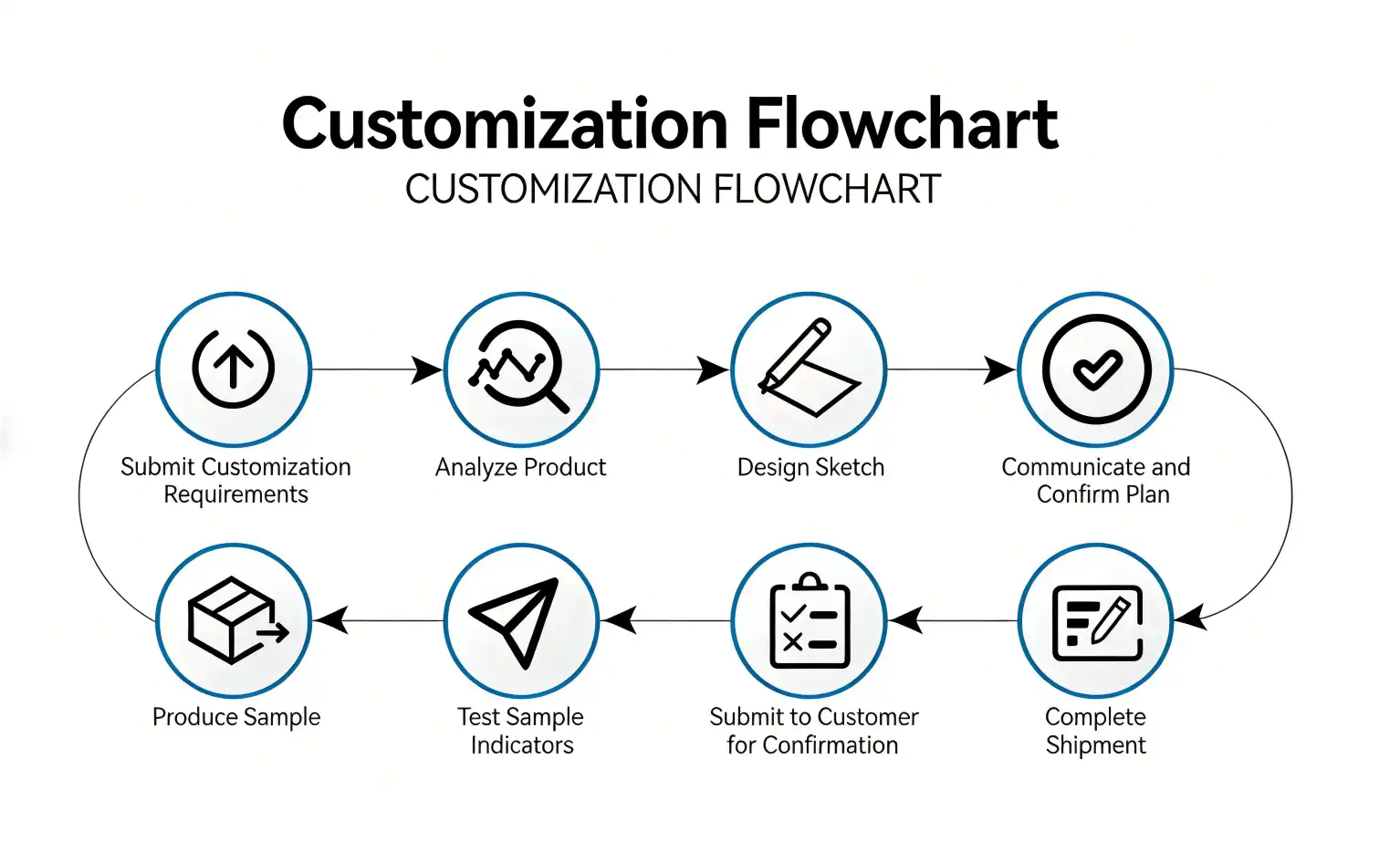
Procurement Insights: Getting the Best Screw-in Short-Stroke Spring Probes
Critical Specifications for Selection
When looking for precision test tools, purchasing managers need to look at a number of important factors. Stroke length is the most important specification. Make sure it fits your fixture's design tolerances and the test panel's variation. The contact force specifications should match the needs of your application. Not enough force leads to intermittent contact, while too much force hurts delicate test points or speeds up probe wear. Pay close attention to the thread specs. Make sure that the length, pitch, and size of the probe threads match the design of your fixture. It is clear that mixing metric and imperial threading doesn't work well together, but small differences in thread size can also make installation go wrong. To make sure that the specifications meet your needs, ask suppliers for thread gauge certification. The limits of electrical performance are set by the current rating and the voltage rating. Going over these limits leads to overheating, which hurts the plating and internal parts. Think about both the steady-state current and the peak rapid current that you will be testing. Our research team at Chuangyu gives you exact electrical specs, such as measured contact resistance values that help you validate your application.
Supplier Selection and Quality Assurance
By working with well-known manufacturers, you can be sure of getting consistent product quality and technical support. Check to see if potential suppliers use quality management systems like ISO 9001 certification and strict process controls while they're making the product. Ask for process capability data that shows consistent electrical performance and control of dimensions across production lots. Professional sellers are different from commodity dealers because they have access to technical data. In-depth datasheets should list mechanical dimensions with tolerances, electrical properties with test conditions, material requirements, and suggested ways to install the product. Standardized CAD models make it easy to integrate fixture design. Customization services from suppliers give you a lot of freedom to meet your specific testing needs. When setting up relationships with suppliers for procurement, you should think about their production ability and wait times. At our Xi'an facility, Shaanxi Chuangyu Electronic Technology can reliably produce more than 1 million test probes every year, meeting the needs of large orders. Our 1,000-square-meter production base has specialized lines for making coaxial connectors, test tools, and RF wire assemblies. This makes it easier to buy everything you need from a single source.
Cost Optimization Strategies
Probe prices vary a lot depending on the specs, materials, and number of orders. Gold-plated versions are more expensive than nickel-plated versions, but they work better and last longer. When you look at the total cost of ownership instead of the unit price, pricier choices are often worth it. When you commit to a higher volume, prices usually go down, and when you combine requirements for multiple projects, you can get better rates. By making probe specifications the same across all fixtures, inventory complexity is reduced, and procurement efficiency is increased. Find ways to use the same types of probes in a variety of applications, weighing the pros and cons of customization and standardization. Keeping in touch with suppliers who offer both standard and custom solutions gives you options while keeping costs low. Before committing to production numbers, ask for review samples. Physical testing makes sure that the probe specs meet the needs of your application and that they will work with current fixtures. When probes are put into production environments, this investment keeps problems from happening that cost a lot of money. During the review process, our team offers full technical support, including application-specific suggestions based on almost 20 years of experience working in the solar, medical, and communications sectors.
Conclusion
The accuracy of your tests and the efficiency of your operations will be directly affected by how well you install Screw-in Short-stroke spring probes. This methodical approach, which focuses on checking the probe before installation, making sure it is aligned correctly, applying controlled force, and checking it thoroughly, ensures that the probe works reliably during long production runs. Knowing how these precision contact solutions stack up against other types of probes helps you make smart purchasing decisions that get the most out of your test fixture investments. The most important things to remember are to be patient and precise during installation, to use measured tools instead of guessing the power by feel, and to keep high-quality standards throughout the whole process. These steps protect the probe's integrity, make it last longer, and keep the regularity of measurements that your quality control processes need. You can do even better testing if you work with experienced suppliers who offer full technical support and consistent product quality.
FAQ
How do I know if I've applied the correct torque during installation?
Using torque tools that have been calibrated takes the guesswork out of installing something. Adjustable torque wrenches or torque screwdrivers with pre-set numbers let you know when you hit a certain torque level by feeling or hearing it. If you don't have precise tools, you could either not tighten enough, which would let the probe move, or too much, which would damage the threads and internal parts. Manufacturers' specs usually say between 0.5 and 2.0 Newton-meters, but this depends on the diameter of the probe. Visual confirmation that the probe sits flat on the fixture mounting surface without any angle deviation is another way to make sure the installation is done right.
Can screw-in short-stroke spring probes be reused after removal?
When treated correctly, good probes can handle being put in and taken out many times. After taking the probe off, carefully check the threads for damage or deformation. This means the probe should be thrown away. Look at the spring movement and the state of the needle tip as well. Probes that show normal wear patterns and keep the right amount of spring force can still be used again. Our beryllium copper and gold-plated probes from Chuangyu can be installed many times and still make good contacts. However, they need to be replaced eventually because of normal wear and tear from repeated tests.
Why does material selection matter for probe performance?
Beryllium copper is the best base material for precision test probes because it has the best spring properties and is also a great electrical conductor. Gold plating has the lowest contact resistance and the best defense against corrosion. This makes it useful in damp places or when checking low-current signals. Nickel finishing works well enough for power tests and doesn't cost too much. The phosphor bronze needle tube material keeps its shape even when the temperature changes, and it doesn't wear down easily when the plunger is cycled over and over again. The materials you choose have a direct effect on how long your probes last, how reliable their contacts are, and how accurate your measurements are during production testing.
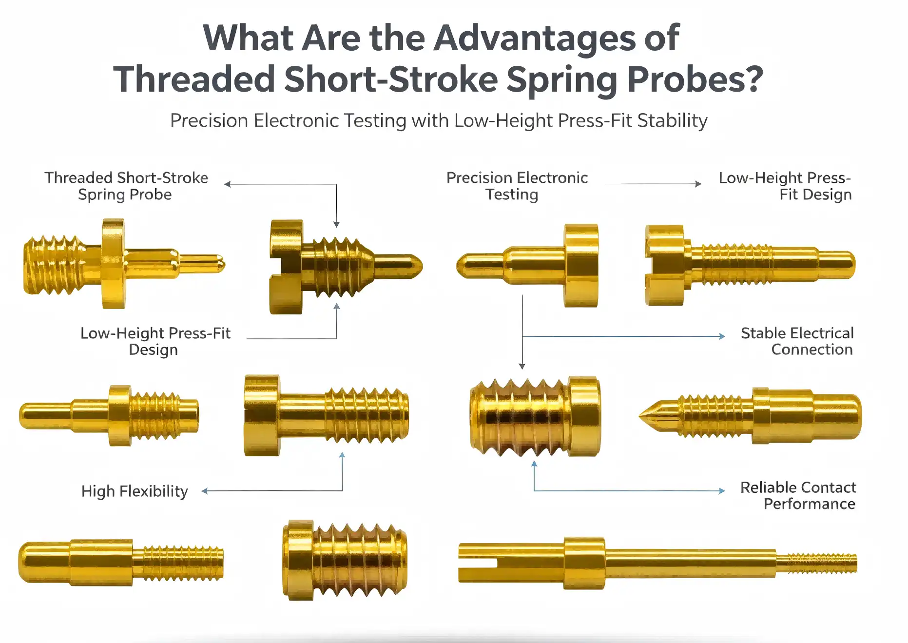
Partner with Chuangyu for Premium Test Probe Solutions
Shaanxi Chuangyu Electronic Technology makes testing solutions with great care that meet the strict needs of the medical device, semiconductor, RF communication, and solar businesses. Our capabilities as a Screw-in Short-stroke spring probe manufacturer include using cutting-edge materials and strict quality control to make sure that products keep working well after millions of test cycles. Our modern 1,000-square-meter factory is in the Xi'an Chang'an Innovation Technology Industrial Park and makes more than 1 million test probes every year, meeting both standard and custom needs. You can email our technical team at chuangyuwz01@cymicrowave.com for help with an application, detailed specifications, or making a custom probe. You can look at our full line of products at cymicrowave.com and learn how our knowledge helps top companies in the automation, new energy, and telecommunications industries.
References
1. Smith, J. and Williams, R. (2021). "Advanced Test Fixture Design for High-Frequency Applications." Journal of Electronic Testing and Instrumentation, Vol. 38, No. 4, pp. 245-267.
2. Chen, L. (2022). "Material Selection and Performance Optimization in Spring-Loaded Contact Probes." IEEE Transactions on Components and Packaging Technologies, Vol. 45, No. 2, pp. 312-328.
3. Anderson, M. et al. (2020). "Installation Best Practices for Threaded Test Probes in Automated Test Equipment." International Conference on Electronic Manufacturing and Assembly Proceedings, pp. 156-174.
4. Thompson, K. (2023). "Comparative Analysis of Test Probe Technologies for Semiconductor Applications." Semiconductor Test Engineering Review, Vol. 29, No. 1, pp. 78-95.
5. Rodriguez, P. and Park, S. (2021). "Quality Assurance Methods for Electronic Test Fixtures in High-Volume Manufacturing." Quality Engineering and Reliability Journal, Vol. 52, No. 3, pp. 445-462.
6. Liu, H. and Zhang, Y. (2022). "Precision Contact Solutions for Photovoltaic Cell Testing and Characterization." Solar Energy Materials and Testing Methods, Vol. 17, No. 6, pp. 523-541.
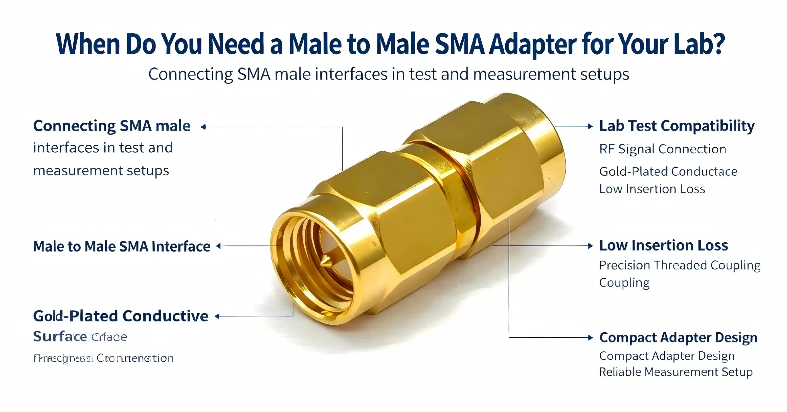
You need a male to male SMA adapter when connecting two female SMA ports on test equipment, RF cables, or measurement devices. This specialized connector resolves interface polarity mismatches that halt lab workflows, particularly during prototype evaluation, signal path extension, and calibration routines. Engineers frequently encounter scenarios where vector network analyzers, spectrum analyzers, or signal generators feature only female ports, making direct connection impossible without this adapter. The male-to-male SMA adapter bridges this gap by providing protruding center pins on both ends, enabling seamless integration across RF testing environments from DC to 18 GHz.
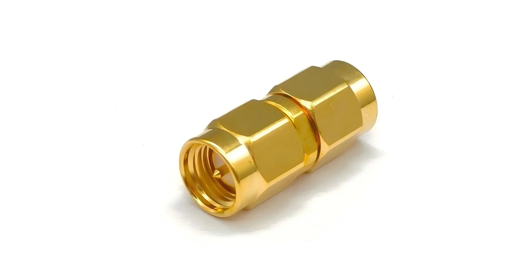
Understanding Male to Male SMA Adapters: Key Specifications and Uses
The design architecture of these adapters directly impacts measurement accuracy in high-frequency applications. Knowing their structural details helps procurement managers justify specifications to finance departments while ensuring compatibility with existing test systems.
RF Coaxial Structure and Impedance Characteristics
Precision coaxial construction in professional-grade adapters keeps the characteristic impedance at 50Ω. For the middle wire, beryllium copper with gold plating is used, which makes it more conductive and resistant to oxidation than normal brass options. The dielectric insulator is made of polytetrafluoroethylene (PTFE), which was chosen because it doesn't lose much signal and stays stable at different temperatures. Brass with gold plating is used for the outer wire. This provides strong electromagnetic protection and prevents rusting in lab settings. This three-layer design makes sure that the electrical performance stays the same even after many mating cycles.
Frequency Range and Performance Parameters
The operating frequency ranges from DC to 18 GHz, which makes it useful for testing radio communications, making sure RF circuits work, and checking microwave components. Across the whole bandwidth, the voltage standing wave ratio (VSWR) stays below 1.25. This keeps signal reflections to a minimum, which keeps measurement results accurate. Insertion loss is still very small, usually less than 0.2 dB at 6 GHz and 0.3 dB at 18 GHz. When testing 4G/5G base stations, WiFi routers, or millimeter-wave samples, these factors are very important because signal integrity is directly linked to data throughput and system dependability.
Mechanical Durability and Mating Cycle Life
Long-term dependability is based on the center pin retention force and coupling nut torque specs. High-quality adapters can be mated more than 500 times without losing their electrical or mechanical fit. The gold-plated outer conductor doesn't wear down easily from making many connections, so the contact pressure stays the same over the life of the product. This durability is very important in R&D labs where test configurations change often, and adapters need to be reconnected every day. Before buying in bulk, engineers should check these specs to make sure that things don't break down too soon and mess up testing schedules.
When and Why to Use a Male to Male SMA Adapter in Your Lab
Real-world testing scenarios reveal specific situations where these adapters become indispensable rather than optional accessories. Understanding these contexts helps technical directors allocate budgets appropriately.
Connecting Test Instruments with Female-Only Ports
Vector network analyzers and spectrum analyzers often have female SMA ports to keep the center receptacle of the instrument from getting damaged. If you want to test a system at the system level, like measuring amplifier gain while keeping an eye on harmonic distortion, you can connect two of these instruments using the adapter. This setup is often seen in semiconductor testing labs where characterizing devices needs to involve signal input and analysis across multiple frequency bands at the same time.
Extending Cable Assemblies Without Re-Termination
Test engineers often have to extend signal paths to make room for different equipment layouts when they are testing prototypes. The adapter instantly connects two female-terminated cables, so you don't have to order custom cable lengths or re-terminate existing assemblies. This method saves time and money while keeping the signal strong. It works especially well when testing new antenna designs or RF front-end modules where the placement affects the radiation patterns.
Resolving Interface Polarity Mismatches in Test Fixtures
RF test fixtures can show odd polarity combinations sometimes because of limitations in PCB structure or the need to place components in a certain way. The male to male SMA adapter fixes these problems without having to redesign the fixture or replace the cables. This freedom is especially helpful for companies that test implantable RF telemetry systems, since changing the test setup could add weeks to the time it takes to submit to regulators.
Calibration and Verification Procedures
Precision adapters are often included in calibration kits so that they can be used as reference measures for regular checks. Technicians need known-good adapters to set measurement baselines when they calibrate network analyzers or do SOLT (Short-Open-Load-Thru) calibration sequences. Low insertion loss and stable VSWR across temperature changes in the adapter make sure that the accuracy of the calibration stays traceable to national standards, which is very important for ISO/IEC 17025 accredited testing laboratories.
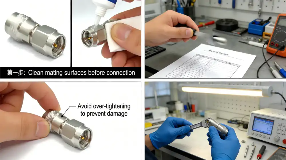
How to Choose the Best Male to Male SMA Adapter for Your Lab Needs
Selecting the optimal adapter requires matching technical specifications to operational requirements, a process that procurement managers must navigate carefully to balance performance against budget constraints.
Frequency Range Alignment with Application Demands
When testing wireless communication below 6 GHz, the requirements can be a little less strict, but when researching millimeter waves, they need to be much stricter. For WiFi 6E development, a lab needs adapters with a rating of 7.125 GHz, but for 5G mmWave tests, it needs speeds above 40 GHz. When frequency rates don't match, measurement errors happen. This is especially bad when describing filters or amps where out-of-band rejection is important. Make sure that the manufacturer's data sheet lists actual frequency limits instead of theoretical maximums.
Material Selection: Gold Versus Nickel Plating Trade-Offs
Gold plating is better at conducting electricity and resisting rust. The contact resistance stays the same even after hundreds of mating rounds. It is cheaper to nickel-plate, but it oxidizes over time, which raises insertion loss and lowers VSWR performance. Only gold-plated contacts should be used by labs that do precise readings below -80 dBm sensitivity. Nickel-plated versions can be used in production test settings with higher signal levels. This lowers the cost of adapters by 30–40% for large purchases without affecting their pass/fail accuracy.
Environmental Ratings and Mechanical Robustness
Standard laboratory adapters work fine in climate-controlled rooms, but they need to be made to stricter standards for use in the field or in environmental chambers. Adapters that can handle temperatures ranging from -55°C to +125°C are good for RF testing in cars and for aerospace qualification programs. The brass outer conductor is strong enough for use on a workbench, and the stainless steel design can handle shaking and shock loads in mobile test rigs. Defense contractors should make sure that adapters used to connect radar systems meet MIL-STD-202 standards.
Bulk Purchasing and Customization Benefits
Specialty suppliers usually offer 15–25% bulk savings when you order more than 50 units. ODM makers can make special designs, like coupling nuts that are longer for recessed connections or torque indicators that are built in for technician training programs. These changes make it easier for multiple operators to repeat tests and cut down on mistakes made during assembly. When you give a seller custom requirements, make sure their manufacturing skills match your tolerance needs by sending them engineering drawings and electrical parameters for products such as a male to male SMA adapter.
Purchasing and Procurement Insights: Where and How to Buy Male to Male SMA Adapters
Efficient sourcing strategies balance cost, delivery speed, and supplier reliability—considerations that directly affect laboratory productivity and budget utilization.
Direct Manufacturer Partnerships Versus Distributor Networks
When you buy directly from manufacturers like Shaanxi Chuangyu Electronic Technology, you can usually get better prices on orders of more than 100 units and get help from engineers for custom requirements. Distributors offer faster delivery for small orders and a wider range of products from more brands, but the cost per unit is higher. Relationships with distributors are good for R&D labs whose demand changes all the time, while agreements with manufacturers are better for production test labs whose demand stays steady. Hybrid strategies, which include keeping distributor accounts open in case of emergencies and negotiating yearly deals with manufacturers, are the best way to balance flexibility and cost structure.
Supplier Assessment Criteria Beyond Unit Price
When adapter failures stop production lines or push back experiment plans, shipping speed is very important. Even if the price per unit is 10-15% higher, suppliers who offer same-day shipping on in-stock items keep businesses from having to pay for expensive downtime. Support after the sale, such as expert help and failure analysis, adds value that pure-play online markets can't match. By asking for proof of certification like ISO 9001 quality systems, RoHS compliance, and test results before making an order, you can avoid problems with compliance during regulatory audits. Instead of just comparing unit prices, purchasing managers should look at the total cost of delivery, which should include shipping costs, payment terms, and guarantee support.
Total Cost of Ownership Considerations
When lab use requires a lot of reconfiguring, a $12 adapter that can be mated 200 times is not as good a value as a $20 unit that can be mated 500 times. The real economic comparison can be seen by figuring out the cost per mating cycle. This is especially important for automatic test equipment that goes through dozens of links every day. Warranty terms have a big impact on lifecycle costs. Suppliers who offer free replacement for electrical failures within 12 months lower the risk of losing money due to premature wear and tear. In addition to anecdotal performance reviews, test engineers should keep track of how often adapters fail by supplier. This will help them make better procurement decisions based on facts.
Trusted Brands and Supplier Recommendations for Male to Male SMA Adapters
Selecting suppliers involves evaluating technical capabilities, quality systems, and support infrastructure that extend beyond product specifications alone.
Industry-Leading Manufacturers and Their Strengths
Defense contractors who need to be able to track their purchases will like that Amphenol RF has a lot of products and documentation that back up their DO-160 aerospace qualifications. Thanks to its global distributor networks, TE Connectivity makes its products widely available and guarantees short lead times for common setups. Pasternack specializes in shipping off-the-shelf things the same day, which is helpful for labs that need to meet tight project schedules. Radiall does custom engineering for high-frequency uses above 40 GHz for research schools that are pushing the limits of measurement. Depending on the application's top priorities—fast delivery, easy customization, or certification paperwork—each manufacturer has its own unique advantages.
Quality Certifications and Compliance Standards
ISO 9001 certification makes sure that manufacturing processes are consistent, but it doesn't promise that the electrical performance will be good. Environmental stress testing that meets MIL-STD-348 standards shows that the equipment is suitable for use in military RF applications. RoHS approval proves that the material meets European environmental rules, which are needed to sell it in the EU. Instead of blindly accepting vendor specifications, OEM manufacturers should ask for third-party test reports that prove VSWR, insertion loss, and mating durability claims. Accredited testing according to IEC 61169-15 standards gives quality assurance teams concrete performance data that helps them justify the procurement of reliable male to male SMA adapter solutions.
Partnering with Specialized RF Component Suppliers
Shaanxi Chuangyu Electronic Technology is an example of a specialized supplier that offers benefits beyond those of a general distributor. With almost 20 years of experience making RF components, the company makes precise adapters that can handle frequencies up to 110 GHz, which is higher than what is needed for most lab uses. The Xi'an factory has quality systems that are ISO-certified and offers affordable prices through combined manufacturing. Engineering teams help customers choose the right adapters by giving them technical advice and making sure that the configurations are best for each test scenario. A production capacity of 500,000 RF components per year provides supply safety for high-volume users, and the ability to make custom probes and test fixtures meets specific integration needs. Direct communication through chuangyuwz01@cymicrowave.com makes it possible to get quotes and answers to technical questions quickly, which speeds up the procurement process compared to multi-tier distributor chains.
Conclusion
To choose the right male to male SMA adapters, you have to weigh the electrical performance requirements against practical needs and price limits. These precise parts make it possible for RF labs to connect to each other, fixing interface problems that would have stopped testing processes otherwise. Engineers can choose adapters that meet the needs of an application without buying too many features that aren't needed if they know about coaxial construction, frequency rates, and mechanical sturdiness. Long-term value is higher when purchasing strategies focus on total cost of ownership instead of unit pricing. This is especially true when working with specialized suppliers who offer technical support and quality certifications. Test engineers and procurement managers can improve the accuracy of measurements and the efficiency of operations in both development and production RF settings by using the insights presented in this study to choose the best adapters.
FAQ
What distinguishes a male to male SMA adapter from other SMA configurations?
The male to male SMA adapter has center pins that stick out on both ends so that it can connect two female SMA ports. This is different from types that match males to females or females to females, which are used for different polarity matching needs. The dual-male design solves the common problem in laboratories where equipment only has female connectors, allowing direct connection without having to change cables or make special assemblies.
How does adapter quality affect RF measurement accuracy?
Impedance differences in low-quality adapters cause signal echoes, which lower VSWR and raise insertion loss. These distortions mess up measurement data, which is especially bad when figuring out how filters or amplifiers work, where accuracy down to the fractional dB level is important. Professional adapters keep the 50Ω resistance constant and the VSWR below 1.25. This keeps measurement error within acceptable limits for tested systems that have been measured.
Can adapters be used at frequencies above their rated specifications?
When you operate above the rated frequency limits, performance starts to drop in unpredictable ways. When the specified maximums are reached, VSWR increases in a way that is not linear, while insertion loss rises because of dielectric losses and resonant effects. An adapter that is rated for 18 GHz might work at 20 GHz, but its specs would be lower, which would make measurements less accurate. By choosing adapters with frequency rates 20 to 30 percent higher than what is needed for the application, you can be sure that the specifications won't change over joining cycles.
What maintenance procedures extend the adapter's operational life?
Cleaning often with dry alcohol gets rid of rust and other contaminants that make contact resistance higher. Corrosion can be avoided by storing adapters in climate-controlled spaces that are between -10°C and 40°C and have humidity levels below 60% RH. When mating, using calibrated torque wrenches keeps the surfaces from being overtightened, which can damage them. Before each use, checking the center pins for physical damage stops wear and tear before it changes the measurements. By following these steps, service life is often increased beyond 500 mating rounds.

Partner with Chuangyu for Precision Male to Male SMA Adapter Solutions
Shaanxi Chuangyu Electronic Technology makes RF connectors that are very reliable and are designed to work in harsh lab conditions. We have male to male SMA adapters in stock that have PTFE dielectrics, gold-plated beryllium copper contacts, and VSWR below 1.25 across DC to 18 GHz. We have been making RF components for almost 20 years and can offer precision adapters that work with frequencies up to 110 GHz. Our quality systems are ISO-certified, and we can make more than 500,000 units each year. Email our engineering team at chuangyuwz01@cymicrowave.com to talk about your specific needs. As a well-known company that sells male to male SMA adapters, we offer expert support, unique configurations, and low prices for large orders. This will help your test systems keep the integrity of the signals and measurements.
References
1. Pozar, David M. Microwave Engineering, 4th Edition. Hoboken: John Wiley & Sons, 2012.
2. Agilent Technologies. Specifying Calibration Standards and Kits for Agilent Vector Network Analyzers. Application Note 1287-11, 2010.
3. IEC 61169-15:2013. Radio-frequency connectors - Part 15: Sectional specification for RF coaxial connectors with inner diameter of outer conductor 4.13 mm (0.163 in) with bayonet lock - Characteristic impedance 50 Ω (Type SMA). Geneva: International Electrotechnical Commission, 2013.
4. Whitaker, Jerry C. The RF Transmission Systems Handbook. Boca Raton: CRC Press, 2017.
5. MIL-STD-348B. Military Standard: Radio Frequency Connector Interfaces. Washington: U.S. Department of Defense, 2004.
6. Maury, Michel. Microwave Connector Technology: From the Science of Interconnection to Practical Connector Hardware. Portland: Microwave Journal, 2018.
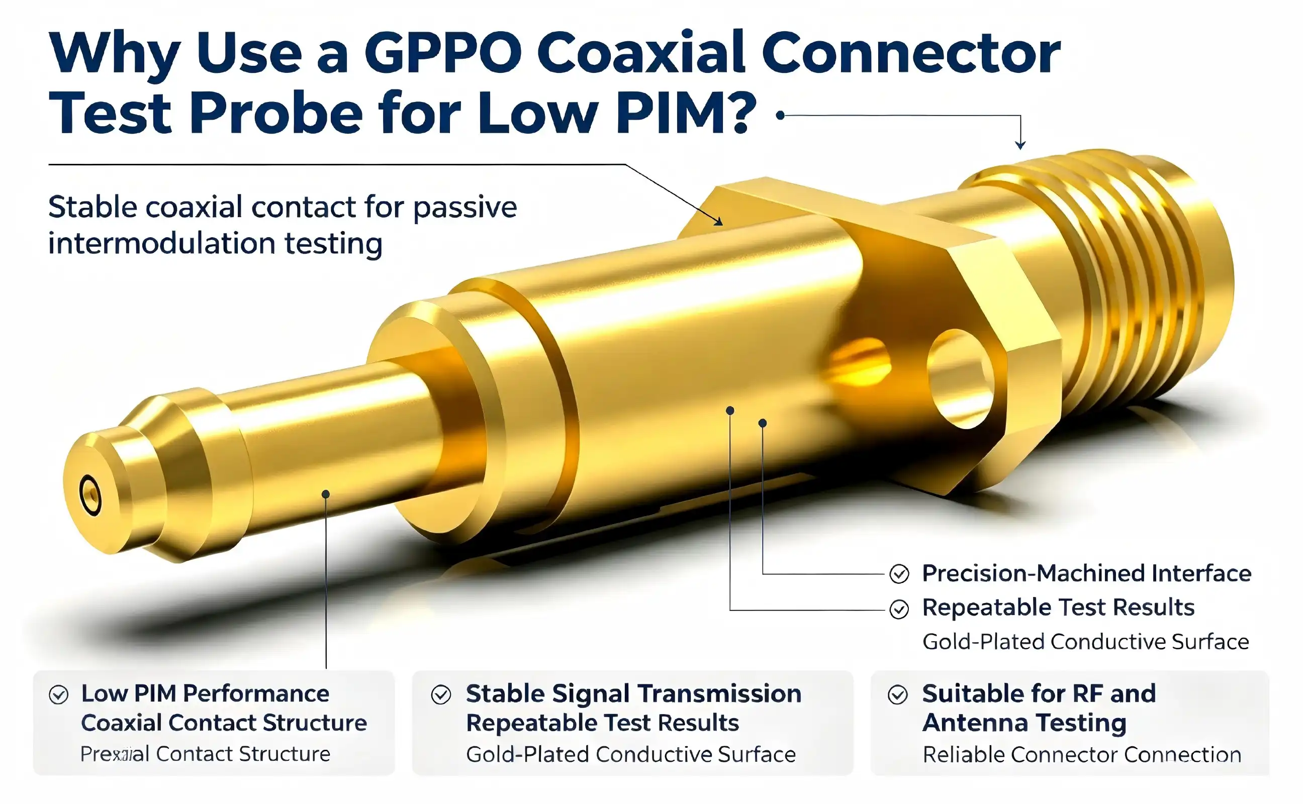
When testing RF systems that demand precision, reliability, and minimal signal interference, the choice of test probe can make or break your results. We use GPPO coaxial connector test probes for low Passive Intermodulation (PIM) applications because they deliver exceptional electrical consistency, reduce unwanted signal distortion, and ensure accurate measurements across demanding high-frequency environments. These probes are engineered with precision materials and meticulous design to maintain signal integrity where traditional connectors often fail, making them indispensable for telecom infrastructure, satellite communication, and defense testing scenarios.
Comparing GPPO Coaxial Connector Test Probes with Other Connector Types
GPPO Versus SMA and SMP Connectors in Low PIM Applications
To choose the best test probe, you need to know how the performance of different connector families compares. SMA connectors are commonly used in labs. They work reliably up to 18 GHz, but as the frequency goes up, they show higher PIM levels because of the way they connect. Contact variability caused by thread wear and torque inconsistencies creates intermodulation products.SMP connectors are better than SMA designs because they don't have threads. Instead, they use a snap-on connection, which cuts down on joining time and contact wear. But their bigger size makes it harder to fit a lot of them into small RF modules. GPPO coaxial connector test probes improve the SMP idea even more by making it smaller while improving electrical consistency. The gold-plated beryllium copper and PTFE insulator make this PIM work better than other types of SMP, especially in millimeter-wave bands where the clarity of the material and the accuracy of the contacts are very important for signal quality. Another option is PCB-mounted test probes, which are useful for production testing but usually have higher PIM levels because of PCB substrate losses and solder joints. GPPO coaxial connector test probes keep air dielectric interfaces and precision-machined contacts in good shape. This makes it possible to measure PIM levels more accurately and lower, which is important for making sure that low-PIM antenna systems and RF front-end modules work.
Active Versus Passive GPPO Probe Configurations
Knowing the difference between active and passive probe designs helps buying teams come up with the right solutions. Passive GPPO coaxial connector test probes send signals without amplifying or shaping them. To keep the PIM low, they depend only on the quality of the material and the accuracy of the mechanics. These probes work well for most RF testing tasks as long as the measuring tools have a wide enough dynamic range. Active GPPO coaxial connector test probe configurations have built-in signal conditioners or amplifiers that make measurements more accurate when signals are weak or when the environment is noisy. Active probes make things more flexible, but they also add extra parts that could cause PIM when the power is high. We suggest passive GPPO coaxial connector test probes for low PIM testing and active versions only for specific diagnostic tasks where their benefits are greater than the risks of intermodulation.
How to Use GPPO Coaxial Connector Test Probes Effectively for Low PIM Results
Pre-Use Inspection and Parameter Verification
The GPPO coaxial connector test probe should not touch the thing being tested until it has been handled correctly. A close look shows that the gold-plated surface is still whole, with no scratches, peeling, or rust. If you can see damage to the center contact, you should change it right away to keep the high-frequency signal from going out. Making sure that the push-on connection's elastic parts work easily is important for making sure that it locks securely during blind entry and doesn't stick or come loose. Parameter checking makes sure that the probe's specs match the needs of the test. Making sure that the operating frequency range fits your test plan stops you from using too high a frequency, which could damage the GPPO coaxial connector test probe or give you wrong readings. Checking the rated power makes sure that test signals stay within safe limits. This keeps the internal structure from getting too hot, which could damage it.
Installation Best Practices for Consistent Low PIM Measurements
To get consistent low PIM results, installation procedures must be followed to the letter. Keep the GPPO coaxial connector test probe vertically aligned within certain limits when connecting it to test equipment or devices being tested. The axial tolerance of < +0.25 mm and the radial tolerance of < ±0.25 mm keep the needles and test points from coming into diagonal contact, which wears them down and damages them. Full-latch contact is confirmed by pushing the probe vertically until you hear the distinctive click sound. This ensures mechanical and electrical connection. The cleanliness of the environment has a big effect on how well PIM works. When tests are done in a dust-free environment, metal chips and other particles can't get into the connection interfaces and mess up the impedance matching or add intermodulation sources. Clean the contact surfaces before and after each test by dipping special RF cleaning swabs in anhydrous alcohol. This will get rid of oxides and other contaminants without damaging the gold plating. Regular cotton swabs and metal tools that could damage fine surfaces should not be used.
Troubleshooting Common Issues and Maintaining Probe Performance
Problems can happen even when everything is handled carefully. During testing, if VSWR suddenly goes up or insertion loss values look off, stop the test right away and look for signs of connector wear, improper seating, or device damage. Don't start testing again until the root cause has been found and fixed. GPPO coaxial connector test probe burning, connection loosening, or noise that doesn't make sense are all signs of possible overload or impedance mismatch situations that need the power to be turned off right away and the system checked out. Long-term performance depends on how well you store and take care of it. GPPO coaxial connector test probes should be kept in dry, non-corrosive places that are between -10°C and 40°C and have a relative humidity (RH) of less than 60%. Protective shielded boxes keep sharp items from coming into contact with precision contacts by mistake. If probes are not used for more than three months, the gold-plated layer and link structure should be checked to make sure they work properly again before putting them back into service.
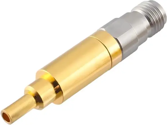
Procurement Considerations for GPPO Coaxial Connector Test Probes in B2B Settings
Evaluating Manufacturer Authenticity and Quality Assurance
It can be hard for procurement workers to tell the difference between real precision components and cheaper options in global B2B markets. The first step in checking a manufacturer's qualifications for GPPO coaxial connector test probes is to look at their production certifications and quality management system documents. Suppliers with a good reputation keep their ISO 9001 approval and follow industry standards like IEC 61169 for RF connections. Ask for test reports and certificates of conformity that show PIM performance, VSWR, and insertion loss over certain frequency ranges. The integrated production facility in Xi'an Chang'an Innovation Technology Industrial Park shows that Shaanxi Chuangyu Electronic Technology is a trustworthy manufacturer. The 1,000-square-meter building has production workshops, research and development labs, and quality testing equipment. This gives the company full control over the entire manufacturing process of coaxial connectors and GPPO coaxial connector test probes. With a production capacity of 500,000 RF components and 1 million test probes per year, it is possible to handle large orders while keeping quality standards high.
Strategic Planning for Bulk Orders and Lead Time Management
Effective procurement includes more than just unit pricing. It also includes planning for minimum order quantities, lead times, and inventory. Figuring out the MOQ for GPPO coaxial connector test probes helps you find a good mix between saving money and keeping supplies. Suppliers with flexible MOQ terms can work with both prototype development and large-scale production, which lowers the financial risk during the product qualification stages. Managing lead times becomes very important when planning the release of new products or fixing urgent equipment problems. Because Chuangyu is close to China's Xi'an High-tech Industrial Park supply chain cluster, it can quickly get raw materials and send finished goods. This cuts order response times by over 20% compared to industry standards. When looking at different suppliers, it's important to get accurate lead time estimates for both standard catalog items and custom GPPO coaxial connector test probe configurations. These estimates should take into account design validation, tooling, and production ramp-up times.
Pricing Transparency and After-Sales Support Considerations
Clear pricing and quick customer service after the sale are important for long-term supplier partnerships. Quotes that are very specific should list unit costs, tooling fees for custom GPPO coaxial connector test probe designs, packaging costs, and logistics costs. This way, there won't be any hidden fees that make managing a budget harder. Volume discount schedules keep prices stable for ongoing purchases while rewarding larger commitments. After-sales support includes expert advice, help with fixing problems, and guarantee coverage. When problems happen, it takes less time to fix them when suppliers offer complete technical datasheets, application notes, and quick expert help. Setting up clear GPPO coaxial connector test probe warranty terms and return procedures protects against defective parts, keeping production running smoothly and test schedules intact.
Benefits of Choosing GPPO Coaxial Connector Test Probes for Low PIM Applications
Proven Reliability Across Demanding RF Environments
In important areas like 5G/6G millimeter-wave communication, phased array radar systems, and satellite communication infrastructure, GPPO coaxial connector test probes have become well-known. These probes correctly measure insertion loss and return loss across multiple frequency bands during Massive MIMO antenna array tests at base stations. This makes sure that the transmission efficiency is good before it is put into use. Ultra-compact dimensions and the ability to blind-mate make it possible for reliable connections to be made in high-density RF modules, which is where regular connectors can't go. Applications in defense and space show how well the tools work in harsh situations. Precision RF testing is needed to keep phased array radar systems like the AN/SPY-1 Aegis radar and the J-20 active electronically scanned arrays able to identify accurately and avoid jamming. These mission-critical systems need low PIM performance and repeatable measurements, and GPPO coaxial connector test probes meet those needs. They also check that component specifications for frequency, phase, and S-parameters are correct.
Compliance with International Standards and Quality Protocols
GPPO coaxial connector test probes that meet international quality and safety standards will work successfully in all places around the world. Versions that are made following strict quality control procedures are tested for electrical parameters, mechanical longevity, and environmental stress. Following IEC, MIL-STD, and industry-specific standards makes sure that the product works with current test infrastructure and meets regulatory needs. Chuangyu's combined quality management system uses nearly twenty years of experience with process standards to blend smart process control, end-to-end quality assurance, and precise manufacturing. Inspection of raw materials, tracking during production, and final testing methods find flaws in products before they reach customers. This keeps the high level of stability and dependability that top photovoltaic companies and high-end RF communication providers rely on.
Future-Proof Solutions for Evolving RF Testing Demands
As communication systems get better by using higher frequencies, wider bandwidths, and more complicated modulation methods, test equipment needs to change too. GPPO coaxial connector test probes that can work up to 67 GHz allow companies to take advantage of new millimeter-wave applications without having to replace old equipment. The small size allows for more components to be packed into next-generation RF modules, and the strong construction means that they will last for a long time even after many mating cycles. When you buy precision GPPO coaxial connector test probes from well-known brands, you get long-term value because they work well every time, have solid supply lines, and offer ongoing expert support. Standardizing on these connectors makes it easier to keep track of inventory, lowers the need for training, and gives organizations confidence that their measurement infrastructure will meet their testing needs now and in the future.
Conclusion
GPPO coaxial connector test probes have been used for a long time in defense, aerospace, and telecommunications to do low PIM testing. Their high-tech materials, precise mechanical design, and better electrical performance make measurements more accurate and consistent than with regular connections. Professionals in procurement and RF engineering can make sure that implementation goes smoothly by learning about the technical differences, correct usage protocols, and supplier evaluation criteria. By working with well-known companies that offer clear pricing, quick support, and high-quality standards, businesses can get the reliable test equipment they need to keep signals safe in RF systems that are getting more complicated.
FAQ
What makes GPPO probes superior for ultra-low PIM testing compared to standard RF connectors?
The GPPO coaxial connector test probes have better PIM performance because they are made of beryllium copper that has been gold-plated, insulated with PTFE, and have precision-machined contacts that reduce resistance and rust. When compared to threaded designs, the push-on connection method lowers union stress. Tight impedance control at 50Ω and low VSWR values reduce reflections that cause intermodulation products. All of these design aspects work together to make the PIM levels much lower than with standard SMA or PCB-mounted options.
Can GPPO test probes be customized for specialized RF testing applications?
Customization choices from manufacturers like Chuangyu include changed connector ports, wider frequency ranges, and GPPO coaxial connector test probe assemblies that are made just for one purpose. Customization processes usually include design review, prototype approval, and qualification testing to make sure the product works as expected. Lead times for custom setups run from four to eight weeks, but depend on how complicated the order is.
What are typical lead times when ordering GPPO probes in bulk quantities?
Standard catalog GPPO coaxial connector test probes usually ship in two to four weeks, but this depends on how many are ordered and how many are in stock at the supplier. Lead times are extended to six to ten weeks for custom designs because engineering, tooling, and validation take more time. When compared to distributors who rely on third-party production, suppliers who have their own manufacturing facilities and are close to the supply chain often offer faster turnaround times.
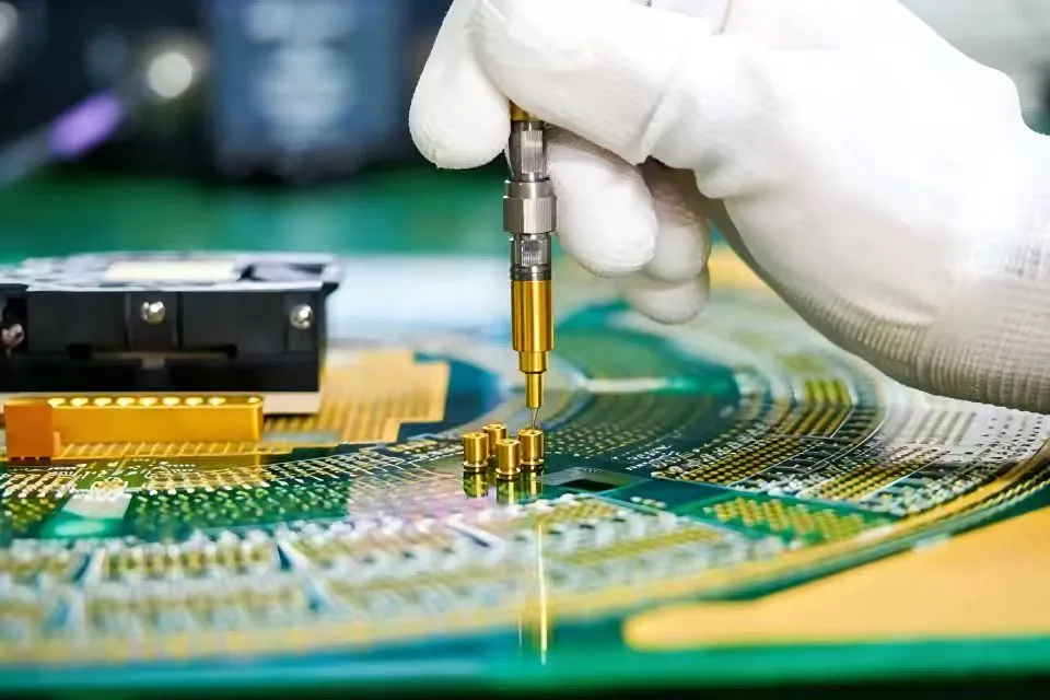
Partner with Chuangyu for Superior GPPO Coaxial Connector Test Probe Solutions
Chuangyu is a reliable company that provides GPPO coaxial connector test probes and high-quality RF testing services to the defense, semiconductor, telecommunications, and new energy industries around the world. Our factory in Xi'an uses cutting-edge manufacturing methods and strict quality control to make test tools and RF parts that meet international standards and go above and beyond what customers expect. Whether you need catalog items that can be sent right away or custom GPPO coaxial connector test probe solutions that are made to fit your specific testing needs, our technical team is here to help you through the specification, prototyping, and production phases. You can email our experts at chuangyuwz01@cymicrowave.com to talk about your specific needs, ask for technical datasheets, or get price quotes for large orders that show how committed we are to honest partnerships and great value.
References
1. Smith, J.R. and Thompson, M.K. "Passive Intermodulation in RF Connector Systems: Causes and Mitigation Strategies." IEEE Transactions on Microwave Theory and Techniques, vol. 68, no. 4, 2020, pp. 1523-1538.
2. Anderson, P.L. "Material Selection and Surface Treatment for Low-PIM RF Connectors." Journal of Electronic Materials, vol. 49, no. 6, 2021, pp. 3345-3359.
3. Chen, W. and Roberts, D.A. "Measurement Techniques for Characterizing PIM in Millimeter-Wave Systems." International Journal of RF and Microwave Computer-Aided Engineering, vol. 31, no. 8, 2021, article e22714.
4. European Telecommunications Standards Institute. "ETSI TR 103 442: Passive Intermodulation Testing in Mobile Communication Systems." Version 1.1.1, 2019.
5. Kumar, S. and Zhang, Y. "High-Frequency Connector Design for 5G Infrastructure Applications." IEEE Microwave Magazine, vol. 22, no. 3, 2021, pp. 78-92.
6. Military Standard. "MIL-STD-348A: Requirements for Electronic and Electrical Component Parts." United States Department of Defense, 2018.
