- English
- French
- German
- Portuguese
- Spanish
- Russian
- Japanese
- Korean
- Arabic
- Greek
- German
- Turkish
- Italian
- Danish
- Romanian
- Indonesian
- Czech
- Afrikaans
- Swedish
- Polish
- Basque
- Catalan
- Esperanto
- Hindi
- Lao
- Albanian
- Amharic
- Armenian
- Azerbaijani
- Belarusian
- Bengali
- Bosnian
- Bulgarian
- Cebuano
- Chichewa
- Corsican
- Croatian
- Dutch
- Estonian
- Filipino
- Finnish
- Frisian
- Galician
- Georgian
- Gujarati
- Haitian
- Hausa
- Hawaiian
- Hebrew
- Hmong
- Hungarian
- Icelandic
- Igbo
- Javanese
- Kannada
- Kazakh
- Khmer
- Kurdish
- Kyrgyz
- Latin
- Latvian
- Lithuanian
- Luxembou..
- Macedonian
- Malagasy
- Malay
- Malayalam
- Maltese
- Maori
- Marathi
- Mongolian
- Burmese
- Nepali
- Norwegian
- Pashto
- Persian
- Punjabi
- Serbian
- Sesotho
- Sinhala
- Slovak
- Slovenian
- Somali
- Samoan
- Scots Gaelic
- Shona
- Sindhi
- Sundanese
- Swahili
- Tajik
- Tamil
- Telugu
- Thai
- Ukrainian
- Urdu
- Uzbek
- Vietnamese
- Welsh
- Xhosa
- Yiddish
- Yoruba
- Zulu
Engineers and procurement managers asking about the 2.92 female to 2.92 male RF wire assembly want the straight goods. This precision coaxial connector technology provides robust, low-loss signal transmission from DC to 40 GHz, with certain high-end variations to 110 GHz. The 2.92 Female to 2.92 Male RF Cable Assembly has a 50Ω impedance design, PTFE dielectric insulation, and MIL-STD-348 connection standards to provide VSWR < 1.4:1 and return loss > −17.5 dB. This assembly is designed for demanding applications such as prototype validation, satellite uplink testing, and defense system integration, ensuring signal integrity is maintained.

Understanding 2.92 Female to 2.92 Male RF Cable Assembly: Key Features and Functions
A 2.92 mm RF cable assembly is more than a connector with a cable attached. It is a system where every material choice directly affects signal behavior at microwave and millimeter-wave frequencies.
Cable Construction and Materials
The cable core is made up of copper-clad steel or silver/tin plated copper conductors. The higher-end versions use silver-plated center conductors to prevent skin-effect losses at higher frequencies. The dielectric is all PTFE and was selected because of its low dielectric constant and dimensional stability, which keeps phase response predictable from DC to 40 GHz. Certain assemblies have been designed using a dual-layer shielding construction utilizing tin-plated copper braid and Nomex braid, which results in improved EMI shielding along with flexibility. The outer jacket is flame retardant, rated -65C to +165C, with a minimum bend radius as small as 0.05".
Connector Interface Design
The 2.92 mm interface is dimensionally compatible with MIL-STD-348. The threaded coupling device provides reproducible coupling with a rated life of no less than 500 insertions. Nice design detail: the male pin is deliberately shorter than the corresponding SMA or 3.5 mm pins so the outer shells connect before the central contacts meet during mating. This sequence avoids misalignment wear. The stainless steel housing is passivated, and the contact elements are produced from phosphor bronze or beryllium copper with gold or silver coating to reduce the contact resistance. Insulation resistance is 5,000 MΩ and beyond. Assembly withstands 600 Vrms.
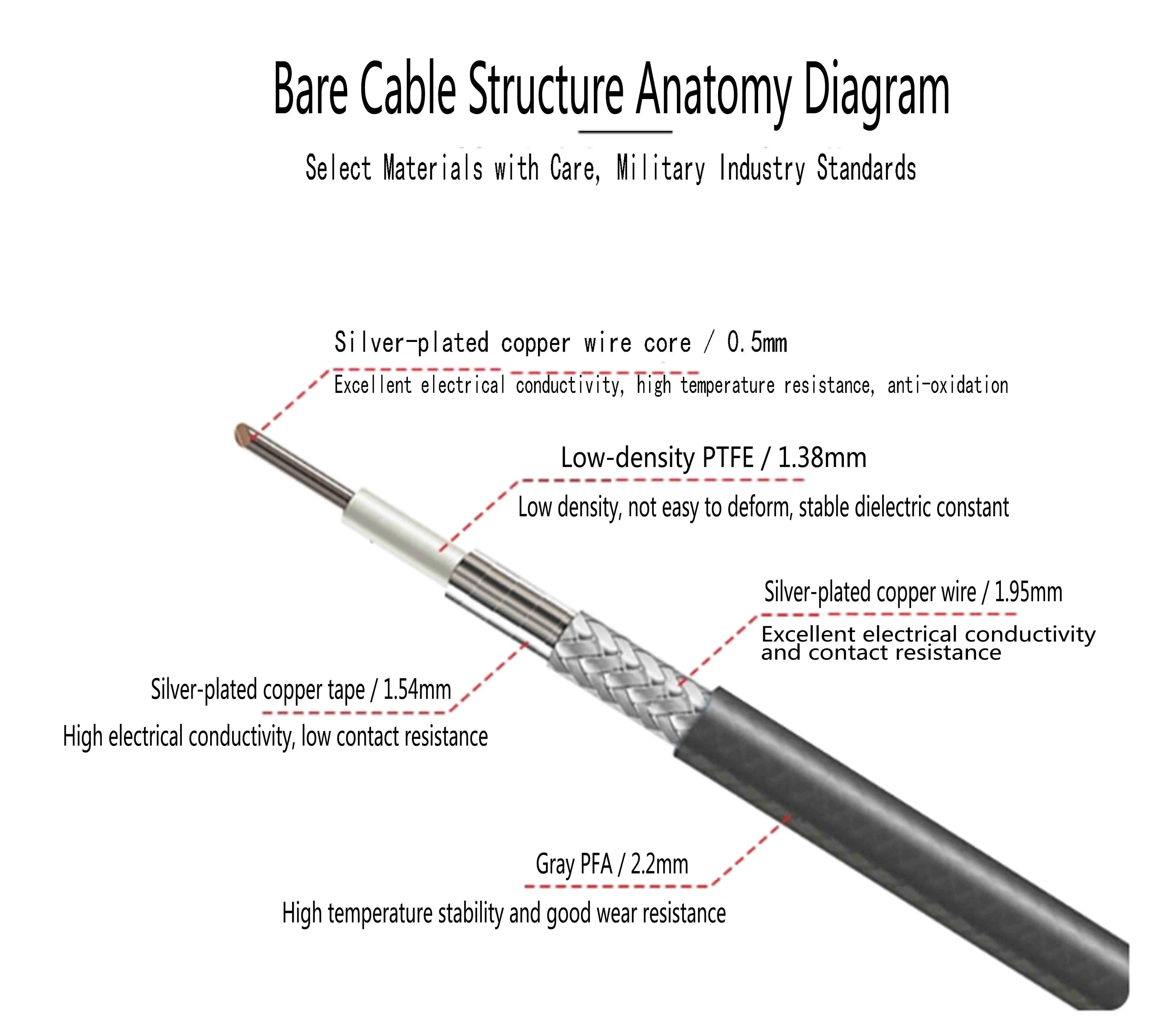
Performance Parameters of 2.92 Female to 2.92 Male RF Cable Assemblies
Signal performance at millimeter-wave frequencies is unforgiving. Small deviations in impedance matching or dielectric uniformity produce measurable reflections and attenuation. Here are the core electrical benchmarks that define this 2.92 Female to 2.92 Male RF Cable Assembly's capabilities:
- VSWR: ≤ 1.4:1 across the operating band; premium-grade assemblies achieve ≤ 1.3:1, indicating near-perfect impedance matching.
- Return Loss: ≥ −17.5 dB, confirming minimal reflected energy at the interface junction.
- Insertion Loss: Extremely low, preserving signal amplitude integrity even at 40 GHz operating frequencies.
- Operating Voltage: Continuous rating of 200 Vrms, with a dielectric withstand rating of 600 Vrms.
- Frequency Range: DC to 40 GHz standard; specialized high-frequency cable types extend this to 110 GHz.
With these performance levels, the 2.92 female to 2.92 male RF cable assembly becomes a reliable solution for network analyzer port connections, spectrum analyzer test ports, and phased-array calibration setups. Compatible cable types include CXN3506 and CXN3507 provide uniform 50Ω impedance across the length of the assembly, minimizing spots of discontinuity degrading high frequency performance.
Semi-rigid assemblies provide reduced phase noise and improved shielding efficacy, making them more suitable for fixed bench-top test arrangements. We provide flexible versions for tight wiring in chassis-mounted systems without sacrificing the electrical specs above.
Comparison of 2.92 Female to 2.92 Male RF Cable Assembly with Alternative Solutions
Choosing between connector families requires an honest look at frequency ceiling, mechanical footprint, and cost per assembly. The table below captures the practical distinctions engineers encounter:
- SMA (up to 18 GHz): Widely available and cost-effective for sub-18 GHz work. However, SMA interfaces degrade rapidly above 18 GHz due to higher-order mode propagation, making them unsuitable for modern 5G mmWave or K-band radar applications. The 2.92 mm connector is mechanically compatible with SMA—meaning they can mate without an adapter—while extending usable bandwidth more than twofold.
- 3.5 mm (up to 34 GHz): Comparable frequency reach and also mates with SMA. The 2.92 mm design edges it out in upper-band performance consistency and durability under frequent mating cycles.
- 2.4 mm (up to 50 GHz): Higher frequency ceiling but smaller outer diameter (4.00 mm vs. 4.55 mm for 2.92 mm), which demands more precise handling. The 2.92 mm interface provides a pragmatic balance of bandwidth and mechanical robustness for most test environments.
- N-type (up to 18 GHz): Larger, robust, and favored for outdoor antenna infrastructure. Its frequency ceiling limits application in precision lab or defense electronics contexts.
The 2.92 female to 2.92 Female to 2.92 Male RF Cable Assembly occupies a practical middle ground—broader bandwidth than SMA or N-type, more durable than 2.4 mm in high-cycle environments, and cross-compatible with the SMA and 3.5 mm installed base through direct mating.

How to Select and Procure the Right 2.92 Female to 2.92 Male RF Cable Assembly
Getting precise RF interconnects means matching the technical specs to the application environment. The frequency range is the major filter. A typical 40 GHz assembly will be adequate for most K-band and Q-band applications, although quantum computing or EHF studies may need 110 GHz-rated versions.
Then, the selection of cable types. The use of flexible cables offers the possibility of dynamic routing with a somewhat larger phase variation when mechanically moved. Semi-rigid cables are ideal for fixed signal pathways, providing excellent phase stability. Custom lengths reduce insertion loss that is not needed; over-length assemblies coil in confined places and create reflections.
assembly must meet MIL-STD-348 dimensional requirements, and connection housings must be properly certified for surface passivation. Demand traceability documentation for plating materials, i.e., gold or silver plating on contact elements directly influences long term contact resistance.
When you are evaluating 2.92 female to 2.92 male RF cable assembly vendors, require measured S-parameter data for each batch, not simply specification documents. Custom lengths normally have a lead time of two to four weeks depending on the kind of cable and connection design.
Common Issues and Troubleshooting Tips for 2.92 Female to 2.92 Male RF Cable Assemblies
Even well-built assemblies need good handling to avoid degradation. Oxidized contact surfaces, over-tightened threads, and bend-radius violations are the most common causes of performance degradation.
Clean connection interfaces at every maintenance cycle using anhydrous ethanol and lint-free cotton swabs. Allow to dry thoroughly before rejoining. Visually check the PTFE dielectric for compression or cracking; mechanical deformation at the dielectric face directly affects the impedance reference plane and corrupts measurement baselines.
Check insertion loss, return loss, and VSWR using a network analyzer every 6 to 12 months. If VSWR reaches 1.5:1 on an assembly previously passed inspection, investigate contact contamination or thread wear. Store unused assemblies with caps on and maintain humidity in storage between 40–60% at temperatures from −10°C to +35°C.
Reduce inspection intervals in high-cycle laboratory conditions. For defense and satellite communication applications, full-performance calibrations should be performed annually to verify that the system meets requirements.
Conclusion
The 2.92 Female to 2.92 Male RF Cable Assembly delivers a compelling combination of wideband frequency coverage, low insertion loss, and mechanical durability suited to demanding RF and microwave environments. Its MIL-STD-348-compliant connector design, PTFE dielectric, and cross-compatibility with SMA and 3.5 mm interfaces give engineers flexibility without sacrificing performance. Proper selection, handling, and periodic testing preserve assembly performance over hundreds of mating cycles. Whether the application is millimeter-wave testing, satellite signal routing, or defense electronics integration, this assembly remains a reliable, verified choice for precision RF interconnect work.
FAQ
1. What is the maximum operating frequency for a standard assembly?
Standard 2.92 mm assemblies are rated to 40 GHz. Specialized high-frequency cable variants—such as those using ultra-low-loss dielectric materials—can extend performance to 110 GHz, making them suitable for EHF research and millimeter-wave system development.
2. Can a 2.92 mm connector mate directly with SMA or 3.5 mm interfaces?
Yes. The 2.92 mm interface is dimensionally compatible with SMA and 3.5 mm connectors, allowing direct mating without adapters. However, the usable frequency of the mated pair is limited by the lower-rated connector in the pair.
3. What are typical lead times for custom-length assemblies?
Custom-length 2.92 female to 2.92 male RF cable assembly orders generally require two to four weeks depending on cable type, length, and connector plating specifications. Volume orders may qualify for reduced lead times.
4. How do I verify assembly quality before deployment?
Request S-parameter test data—specifically S11 and S21 curves—from the manufacturer. Verify VSWR ≤ 1.4:1 and return loss ≥ −17.5 dB across the rated frequency band before integrating any assembly into a production or test system.

Partner with Chuangyu for Precision 2.92 Female to 2.92 Male RF Cable Assembly Solutions
Chuangyu manufactures and supplies precision 2.92 female to 2.92 male RF cable assemblies built to MIL-STD-348 standards, with millimeter-wave coverage up to 110 GHz. As a trusted 2.92 Female to 2.92 Male RF Cable Assembly manufacturer, Chuangyu offers custom lengths, cable type selection, and full S-parameter traceability. Contact our engineering team directly at chuangyuwz01@cymicrowave.com to request technical specifications and a project-specific quotation.
References
1. IEEE Transactions on Microwave Theory and Techniques — 2019
2. Microwave Journal — 2021
3. MIL-STD-348B: Interface Standard for RF Connectors, U.S. Department of Defense — 2021
4. RF and Microwave Engineering: Fundamentals of Wireless Communications, Pozar, D.M., Wiley — 2011
5. IPC/WHMA-A-620: Requirements and Acceptance for Cable and Wire Harness Assemblies — 2017
6. Journal of Electronic Testing: Theory and Application (JETTA) — 2020
