- English
- French
- German
- Portuguese
- Spanish
- Russian
- Japanese
- Korean
- Arabic
- Greek
- German
- Turkish
- Italian
- Danish
- Romanian
- Indonesian
- Czech
- Afrikaans
- Swedish
- Polish
- Basque
- Catalan
- Esperanto
- Hindi
- Lao
- Albanian
- Amharic
- Armenian
- Azerbaijani
- Belarusian
- Bengali
- Bosnian
- Bulgarian
- Cebuano
- Chichewa
- Corsican
- Croatian
- Dutch
- Estonian
- Filipino
- Finnish
- Frisian
- Galician
- Georgian
- Gujarati
- Haitian
- Hausa
- Hawaiian
- Hebrew
- Hmong
- Hungarian
- Icelandic
- Igbo
- Javanese
- Kannada
- Kazakh
- Khmer
- Kurdish
- Kyrgyz
- Latin
- Latvian
- Lithuanian
- Luxembou..
- Macedonian
- Malagasy
- Malay
- Malayalam
- Maltese
- Maori
- Marathi
- Mongolian
- Burmese
- Nepali
- Norwegian
- Pashto
- Persian
- Punjabi
- Serbian
- Sesotho
- Sinhala
- Slovak
- Slovenian
- Somali
- Samoan
- Scots Gaelic
- Shona
- Sindhi
- Sundanese
- Swahili
- Tajik
- Tamil
- Telugu
- Thai
- Ukrainian
- Urdu
- Uzbek
- Vietnamese
- Welsh
- Xhosa
- Yiddish
- Yoruba
- Zulu
knowledge
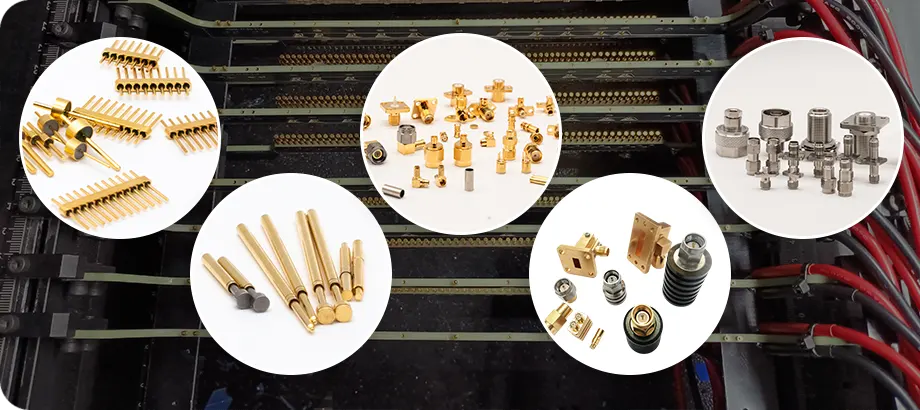
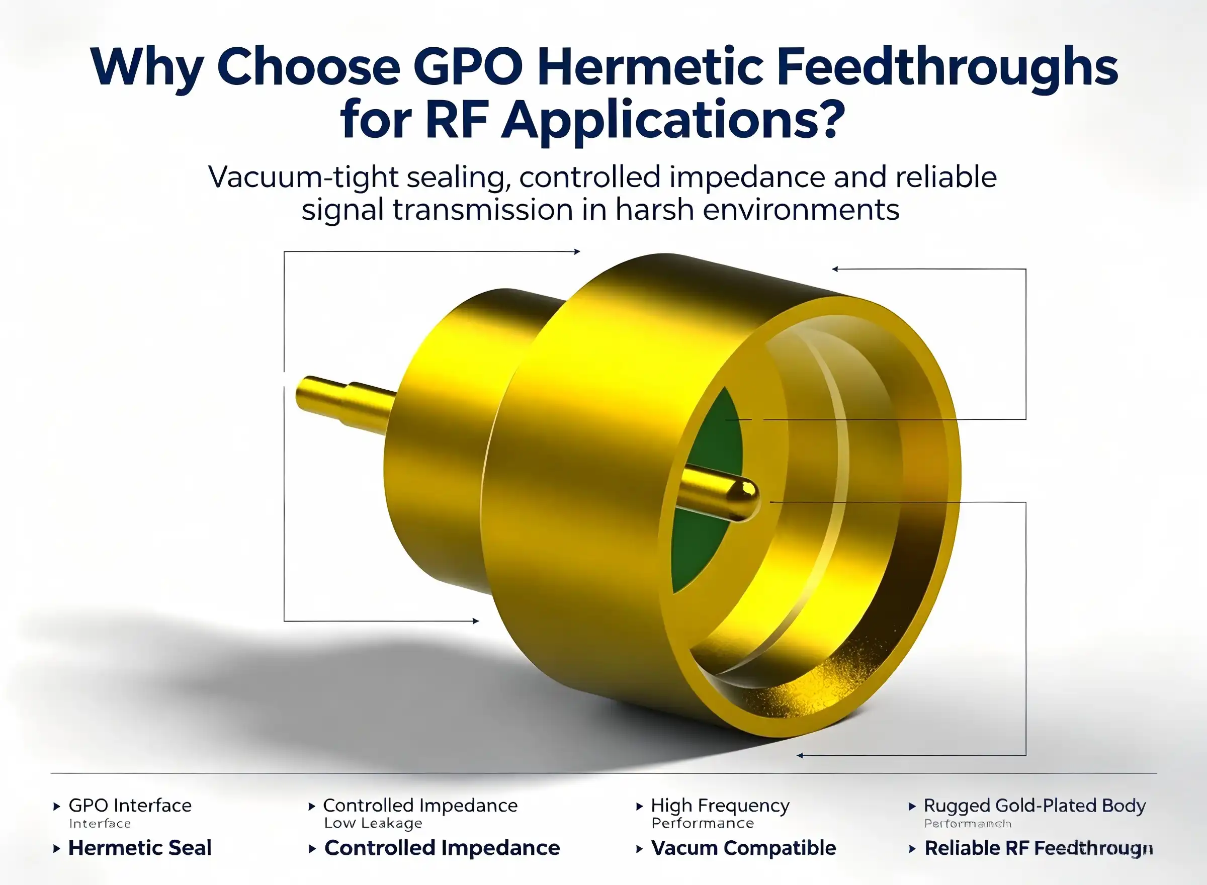
GPO HERMETIC FEEDTHRUS are the precise solution engineers rely on to maintain signal integrity. These ultra-compact, glass-to-metal sealed coaxial connections provide airtight RF transmission routes through enclosure walls under high pressure, temperature, and vacuum conditions. Whether developing satellite payloads, implantable medical devices, or semiconductor test chambers, GPO hermetic feedthrus provide the 50Ω impedance stability and environmental isolation demanding applications need. This book leads procurement experts and design engineers through the structural benefits, application fields, installation best practices, and sourcing concerns that make these components a need in high-reliability RF systems.

Understanding GPO Hermetic Feedthroughs and Their Role in RF Applications
The GPO Hermetic Feedthru (SMP) is the protected version of the ultra-small push-in coaxial connection. It was engineered for situations where a regular connector would allow moisture, gas, or other contaminants to affect how well the system works.
Core Material and Sealing Architecture
Kovar alloy that meets ASTM F15 standards is used for the housing and center wire, paired with Corning 7070 lithium potassium borosilicate glass as the dielectric. This glass-to-metal matched seal achieves a leak rate of 1.01325×10⁻³ Pa·cm³/S, which is a requirement found in standards for precision vacuum and aerospace engineering [1]. If the plating layer remains at least 2μm, the gold-plated exterior will not rust in salt mist environments.
Electrical Performance Specifications
The connector has a characteristic impedance of 50Ω from DC to 40 GHz, with some high-end models covering up to 65 GHz. Important electrical factors include:
- VSWR: ≤1.4, which means that very little power is reflected across the working band
- Insertion loss: ≤0.09×√(f_GHz), which means that signal reduction stays predictably low
- Insulation resistance: At least 1000 MΩ, necessary to stop cross-talk in dense multi-channel setups
- Dielectric withstand voltage: 300 Vrms, supporting high-power RF situations
Based on these specs, the GPO Hermetic Feedthru is much better than non-hermetic options in terms of both signal quality and environmental resistance.
Mechanical and Environmental Ratings
The connector can be inserted and removed up to 500 times (limited detent type), works in temperatures ranging from -55°C to +165°C, and meets MIL-STD-202G standards for vibration and shock [2]. These ratings are important when parts have to deal with launch vibrations in spacecraft platforms or repeated temperature changes in industrial vacuum systems.

Comparing GPO Hermetic Feedthroughs with Alternative Solutions
Under normal circumstances, non-hermetic GPO Hermetic Feedthroughs are acceptable but become liabilities when moisture penetration, pressure differential, or particle contamination are threats to system stability. Ceramic-sealed GPO HERMETIC FEEDTHRUS have comparable leak rates but are fragile under vibration and do not have the push-in convenience of the GPO Hermetic Feedthru interface. The Kovar-glass combination here is an example of a glass-to-metal seal that balances the thermal expansion coefficients and so reduces the chance of seal breaking during large temperature fluctuations. This is a proven procurement benefit for military- and space-grade electronics [3].
Procurement teams face the risk of early field failures with generic items from unqualified vendors who typically don't provide helium leak-rate certification or gold plating thickness criteria. Chuangyu’s GPO Hermetic Feedthru provides monitored material certifications and the ability to confirm leaks using a helium mass spectrometer before shipment, providing procurement managers with written confirmation of conformity prior to shipping the items.
Benefits of Choosing GPO Hermetic Feedthroughs for Your RF Procurement
To understand why the GPO Hermetic Feedthroughs outperform alternatives in real-world deployments, it is necessary to look at both the engineering data and the operational outcomes reported by engineers. Here are the core advantages that directly solve problems with production and system reliability:
- Verified hermeticity at ≤1.01325×10⁻³ Pa·cm³/S enables use in equipment that makes semiconductor wafers and keeps the vacuum level at ≤10⁻⁵ Pa, where even trace outgassing degrades process yield [4].
- Broadband frequency coverage (DC–40 GHz, optional 65 GHz) supports the full signal chain of 40 GHz vector network analyzer calibration units and millimeter-wave test chambers without component substitution.
- Thermal stability from −55°C to +165°C satisfies both cryogenic test bench requirements and high-ambient industrial enclosures within a single component SKU, which makes inventory management easier.
- MIL-STD-202G compliance means the same connector qualifies for radar, electronic warfare sealing, and satellite RF front-end modules without additional qualification testing.
- Gold-plated Kovar construction eliminates galvanic compatibility concerns when mating with standard SMP/GPO wire assemblies, preserving phase consistency across multi-channel measurement systems.
These advantages collectively reduce system-level risk, shorten qualification timelines, and lower total cost of ownership in aerospace, defense, medical, and industrial vacuum applications. Procurement teams that specify hermetic feedthroughs early in the design process avoid expensive board-level redesigns caused by moisture failures in the field.
Procurement Guide for GPO Hermetic Feedthroughs
When looking for precision GPO HERMETIC FEEDTHRUS, you need to pay close attention to specification traceability, lead time management, and supplier qualification.
Installation and Integration Considerations
Hermetic seal and electrical performance are guaranteed by correct installation. Use a high-frequency soldering iron and maintain the temperature at ≤260°C while soldering to minimize thermal stress on the glass dielectric. A specific mold is needed to produce a draw force of 10 N or more of wire-core to center conductor in crimping setups. Helium mass spectrometer leak detection ensures that the assembled feedthrough fulfills the system leak-rate criteria, and not only the component-level requirements, prior to installation into vacuum systems. For multi-channel assemblies, the insertion loss is adjusted for all channels to maintain the phase stability required by test and phased-array systems [5].
Maintenance, Inspection, and Fault Management
The network analyzer is used every three months for VSWR and insertion loss checks to identify gradual performance loss before it impacts system output. Annual helium leak detection is used for long-term seal strength monitoring, notably in temperature cycling situations. Clean contact surfaces using anhydrous ethanol on a lint-free cloth. Avoid chlorinated or acidic solvents, which degrade gold plating. To avoid contact with metallic debris, store idle connections in a sealed, dry location with humidity < 60%. If you see fractures in the glass seal or an abnormal spike in VSWR, replace the unit immediately—uncertified individuals attempting to disassemble it may cause irreparable damage to the seal.
Case Studies and Application Evidence
GPO Hermetic Feedthroughs have provided satellite communication RF front-end modules with the ability to consistently provide RF signals in vacuum-sealed compartments when hermeticity and DC-to-40 GHz coverage are required. Defense radar programs rely on the −55°C cold-start rating and MIL-STD-202G shock compliance to ensure platform qualification criteria are met. These connectors are selected by manufacturers of implanted RF treatment devices for their biocompatibility and the durable glass-to-metal seal. Chip producers use vacuum compatibility of 10^(-5) Pa to keep the process uncontaminated by cheaper feedthroughs. For the 40 GHz VNA calibration modules, the engineers indicate that the corrected insertion loss of ≤0.09×√(f_GHz) puts the measurement error within acceptable bounds [6].
Conclusion
GPO HERMETIC FEEDTHRUS represent a well-thought-out solution to getting signals through environmental barriers without affecting quality or long-term reliability. The Kovar-glass seal architecture, 50Ω broadband performance to 65 GHz, and MIL-STD-202G mechanical ratings all work together to support tough deployments from satellite payloads to implantable medical devices. When procurement teams know these specs, they can make faster, less risky choices about sourcing. Chuangyu's production base in Xi'an can make 500,000 RF components every year, ensuring a steady supply of high-quality parts with traceable standards.
FAQ
1. Are GPO hermetic feedthrus suitable for frequencies above 40 GHz?
Normal models can handle DC to 40 GHz. Some high-end models go up to 65 GHz and use the same VSWR ≤1.4 and insertion loss method. For millimeter-wave uses close to 110 GHz, get in touch with Chuangyu's engineering team to talk about custom setups.
2. Can these feedthrus be customized for non-standard vacuum or pressure environments?
Yes, Chuangyu can make OEM and ODM configurations, such as changing the number of pins, the shape of the flanges, and providing helium leak certification before shipping based on the customer's chosen leak-rate limits.
3. What is the typical lead time and warranty coverage?
Most of the time, standard setups arrive within the agreed-upon production windows. Chuangyu offers a warranty that is backed by certifications of traceable materials and will replace any unit that has a cracked glass seal or VSWR that isn't within the acceptable range.
4. How do I verify seal integrity after installation?
The usual way to find leaks in the industry is with a helium mass spectrometer. Do this test before putting the assembly into vacuum service, and then repeat it annually to check on the seal's long-term health.
5. What cleaning agents are safe for gold-plated Kovar connectors?
Only use anhydrous ethanol on a lint-free cloth. Cleaners and solvents that are chlorinated or acidic hurt the gold plating and speed up corrosion at the seal contact interface.

Partner with Chuangyu for Precision GPO Hermetic Feedthroughs
Chuangyu's Xi'an factory makes carefully approved GPO HERMETIC FEEDTHRUS, with an annual capacity of 500,000 RF components and full traceability from raw materials to finished assembly. As a reliable manufacturer and supplier, Chuangyu offers custom configurations, pre-delivery leak certification, and quick technical support. You can email the team directly at chuangyuwz01@cymicrowave.com.
References
1. IPC/WHMA-A-620, IPC, 2017. Standards for hermetic seal verification in electronic assemblies.
2. MIL-STD-202G: Test Methods for Electronic and Electrical Component Parts, U.S. Department of Defense, 2002.
3. Kovar Alloy Technical Data, Carpenter Technology Corporation, 2020. Glass-to-metal seal thermal expansion compatibility.
4. Semiconductor Equipment and Materials International (SEMI) Standards F47, SEMI, 2019.
5. Pozar, D.M., Microwave Engineering, 4th ed., Wiley, 2011. Impedance matching and insertion loss in RF transmission systems.
6. Keysight Technologies Application Note: VNA Calibration Standards to 40 GHz, Keysight, 2021. Measurement uncertainty and connector insertion loss specifications.
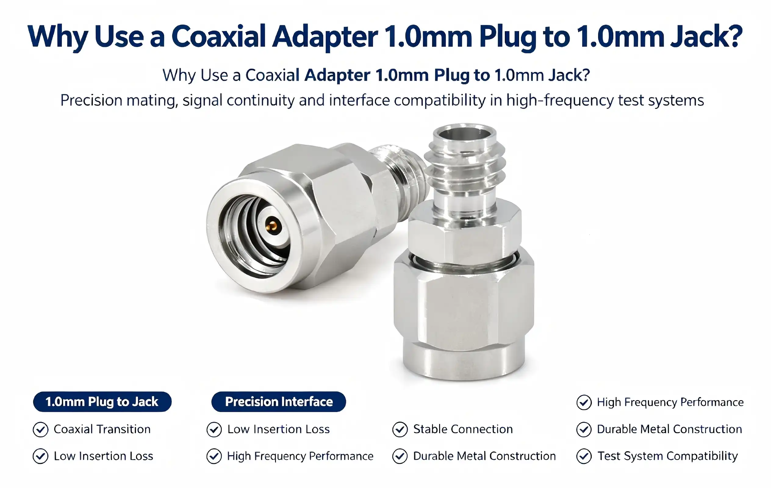
A Coaxial adapter 1.0mm plug to 1.0mm jack solves one of the most persistent challenges in high-frequency RF testing: polarity mismatch between same-series interfaces. When your vector network analyzer, spectrum analyzer, or RF test fixture presents a male port where you need a female connection—or vice versa—this compact gender converter restores continuity without redesigning your cable assembly. Operating from DC to 110 GHz with a VSWR ≤1.35, it maintains signal integrity across millimeter-wave bands. For R&D engineers and procurement managers working with 5G chips, radar modules, or wafer-level test systems, this adapter is not optional—it is infrastructure.

Understanding the Coaxial Adapter 1.0mm Plug to 1.0mm Jack
This standard for a 1.0mm coaxial connector was created to expand RF testing into the W-band and D-band frequency ranges. It specifies a precise interface with an outer conductor inner diameter of 1.0mm. This compact shape makes it possible to send signals up to 110 GHz, which is higher than what bigger plugs like the 2.4mm (rated to 50 GHz) or 1.85mm (rated to 67 GHz) can do ².
Structural Architecture
The adapter has a coaxial structure with a characteristic impedance of 50Ω. The middle wire is made of beryllium copper that has been covered with gold. This material was chosen because it has low contact resistance and springiness. Polyetherimide (PEI) is used as the shielding dielectric because it has stable dielectric properties over a wide temperature range. The outer conductor is made of passivated stainless steel, which makes it resistant to corrosion and dimensionally accurate in size. One end has a 1.0mm male connection with a pin that sticks out, and the other end has a 1.0mm female connector with a hole inside. This gender change device fixes interface polarity problems within the same 1.0 mm connector family without the need for extra adapters or cable extensions ².
Performance vs. the 1.3mm Variant
The Coaxial adapter 1.0mm plug to 1.0mm jack can work at frequencies up to about 90 GHz, which means it can be used for a lot of Ka-band and V-band tasks. When your test setup needs full coverage up to 110 GHz, like when characterising D-band 5G/6G chips or validating car radar at 77 GHz and above, the 1.0mm interface is the right choice. The gap in performance is not small; it is the difference between a correct test and a faulty one.
Why Choose a 1.0mm Coaxial Adapter?
Engineers who work with RF and microwaves already know that every inactive part of a signal path adds to the error of measurements. Picking the correct adapter isn't just a matter of buying something; it's also about making sure the signal stays strong.
The main reasons why this adapter is the best choice for hard tasks are listed below:
- Millimeter-wave test coverage: With an operating range of DC to 110 GHz and VSWR ≤1.35, the adapter supports interface conversion for vector network analyzers and spectrum analyzers used in 5G/6G chip testing, phased array antenna characterization, and millimeter-wave radar development. Signal fidelity is preserved across the full band ³.
- Mechanical durability for repeated use: The stainless steel outer conductor withstands mechanical stress without deformation. The center pin retention force meets or exceeds 4 lbs, and the insertion/extraction lifecycle is rated at ≥500 mating cycles. In high-throughput test environments, this longevity matters directly to cost-per-test metrics.
- Material-driven reliability: Gold plating on the beryllium copper center conductor resists oxidation and maintains stable contact resistance over time. This is particularly relevant in semiconductor testing environments where interface degradation introduces measurement drift.
- Compact form factor: The 1.0mm connector's compact geometry allows integration into dense test fixtures, wafer-level probing systems, and miniaturized RF modules where larger adapters create mechanical interference.
When procurement managers choose connectors for RF test infrastructure, 5G base station integration, aircraft RF component testing, and medical device equipment, these benefits help them deal with signal, mechanical, and space issues.
Choosing this connector also makes designing the system easier. A single 1.0mm plug to jack adapter fixes the polarity problem right away, so you don't have to rebuild a wire assembly or buy a special extension.
Connection Best Practices
Align the interface every time before you use it. Tighten with a measured torque wrench to the stated ≤0.41 Nm. If you over-torque, the outer conductor will bend, and if you under-torque, the electrical contact will become unstable. Do not insert it at an angle. All high-frequency measurements should be done in a shielded area to stop electromagnetic interference from the outside that could mess up data in the 110 GHz range.

Comparing 1.0mm Coaxial Adapters: Choosing the Best Solution
Manufacturers of precision 1.0mm RF adapters include Maury Microwave, Rosenberger, and Chuangyu. Each has its own benefits when it comes to design accuracy, OEM flexibility, and pricing ⁴.
Chuangyu's Coaxial adapter 1.0mm plug-to-1.0 mm jack adapter is made to meet international standards, and its Xi'an factory can make more than 500,000 RF components every year. The gold-plated beryllium copper middle pin, passivated outer wire made of stainless steel, and PEI dielectric are all examples of materials that meet MIL-grade performance standards. With almost twenty years of experience making RF connectors, we can offer OEM customisation, such as custom wire assemblies and non-standard layouts, with faster prototyping processes than the average in the industry.
Total cost of ownership is more important than unit price when figuring out cost-effectiveness. A high-quality adapter that has been tested and certified to work at 110 GHz and rated for at least 500 insertion cycles has a lower replacement frequency and fewer test interruptions than cheaper options that are rated to narrower frequency ranges and have shorter mechanical lifespans.
Procuring 1.0mm Coaxial Adapters for Your Business Needs
When buying precision RF connectors for business use, it's better to deal directly with makers instead of just using marketing platforms. Direct OEM sourcing gives you access to quality certifications, materials that can be tracked, set lead times, and warranties. These are all important when you need to specify parts for defence, medical, or telecommunications applications that need compliance paperwork ⁺.
When buying something, it's important to make sure that the supplier's quality management system includes lifetime testing, VSWR measurement validation, and dimensional checking. When supply chain managers are making resilient sourcing plans, it's important to know about the minimum order amounts, the availability of prototypes, and the supplier's ability to go from small R&D samples to large production volumes.
Chuangyu can handle both small orders for prototypes and large production runs. Its integrated production, R&D, and warehouse layout in Xi'an Chang'an Innovation Technology Industrial Park cuts order response times by over 20% compared to industry averages.
Ensuring Long-Term Performance and Reliability
Pre-Use Inspection and Installation
Before each use, check the outer wire for deformation, make sure the gold metal isn't peeling or corroding, and make sure the center pin or socket doesn't have any oxidation or damage. If an adapter fails this test, it should be replaced right away. Do not keep trying with a broken part. When installing, make sure the interface is fully lined up before applying torque, and don't go over 0.41 Nm.
Cleaning and Storage Protocols
Use a special RF swab that has been wet with anhydrous alcohol to clean the interface. Keep adapters in a dry, covered container that is away from toxic gases and with a humidity level of less than 60% RH. Store them in a room that is between -10°C and 40°C. If VSWR readings go up or down without warning, or signal attenuation rises for no apparent system-level reason, check the adapter right away for wear or problems with fitting. Stop using it until the problem is fixed. Putting a broken adapter back into service messes up readings and speeds up mechanical failure ⁶.

Conclusion
The Coaxial adapter 1.0mm plug to 1.0mm jack is a precision-needed part, not a common one. For testing millimetre waves, 5G/6G systems, aircraft RF systems, and wafer-level components, this cable is a must-have. It has a 50© coaxial design, a gold-plated beryllium copper center conductor, a passivated stainless steel outer body, and has been tested to work at 110 GHz. It is important to choose the right adapter from a reputable manufacturer that supports OEM customisation, provides traceable quality documentation, and ensures consistent mechanical reliability. This will protect both the accuracy of measurements and the long-term investment in infrastructure.
FAQ
1. What is the maximum operating frequency of a 1.0mm coaxial adapter?
The standard for a 1.0 mm coaxial connection allows it to work from DC to 110 GHz. Because of this, it is the best choice for D-band tests, characterising 5G/6G chips, and millimeter-wave radar uses where lower-rated connectors would cause measurement mistakes.
2. Can a 1.0mm plug-to-jack adapter be used with existing 1.0mm cable assemblies?
Yes. The adapter works with all standard 1.0mm RF cables and equipment connections, so you don't have to buy new cable kits to fix gender mismatches within the same connector family.
3. How do I know when to replace my adapter?
If the outer conductor is deformed, the gold metal is peeling, the center pin is oxidised, or the VSWR numbers rise without reason while testing, the adapter should be thrown away and replaced. The service life is rated for at least 500 insertion rounds, but with proper care, it lasts a lot longer.
4. What is the difference between a 1.0mm and a 1.3mm coaxial adapter?
The 1.0 mm version can handle up to 110 GHz, while the 1.3 mm version can handle about 90 GHz. The right choice varies on how high a frequency your test application can handle.
5. Does Chuangyu offer OEM customization for 1.0mm adapters?
Yes, Chuangyu can make custom configurations, cable assemblies that fit your needs, and designs that aren't standard. They can also make prototypes faster and increase their production capacity as needed.

Partner with Chuangyu for Precision 1.0mm RF Adapter Solutions
RF experts in the 5G, military, semiconductor, and medical fields accept Chuangyu's verified Coaxial adapter 1.0mm plug to 1.0mm jack options. If you're looking for a top-quality Coaxial adapter 1.0mm plug to 1.0mm jack, Chuangyu has been making RF connectors for almost 20 years and can make more than 500,000 of them every year. They also offer full OEM customisation support. You can look at all of our products and email our expert team at chuangyuwz01@cymicrowave.com to get a price or talk about the details of your project.
References
1. Anritsu Corporation. Connector Care and Maintenance Guide. Anritsu, 2019. https://www.anritsu.com/en-US/test-measurement/support/technical-notes/microwave-connector-care
2. Maury Microwave. Precision Coaxial Connectors and Adapters Technical Reference. Maury Microwave Corporation, 2021. https://www.maurymw.com/MW_RF/Adapters.php
3. IEEE Standards Association. IEEE Std 287-2007: Standard for Precision Coaxial Connectors at RF, Microwave, and Millimeter-Wave Frequencies. IEEE, 2007. https://standards.ieee.org/standard/287-2007.html
4. Rosenberger. RF Connectors and Adapters Product Catalog: 1.0mm Series. Rosenberger Hochfrequenztechnik, 2022. https://www.rosenberger.com/en/products/rf-connectors/1-0mm.php
5. IPC Association. IPC-A-620: Requirements and Acceptance for Cable and Wire Harness Assemblies. IPC, 2017. https://www.ipc.org/ipc-a-620
6. Keysight Technologies. Millimeter-Wave Network Analysis: Best Practices for Connector Use and Care. Keysight Technologies, 2020. https://www.keysight.com/us/en/assets/7018-06840/application-notes/5992-3666.pdf
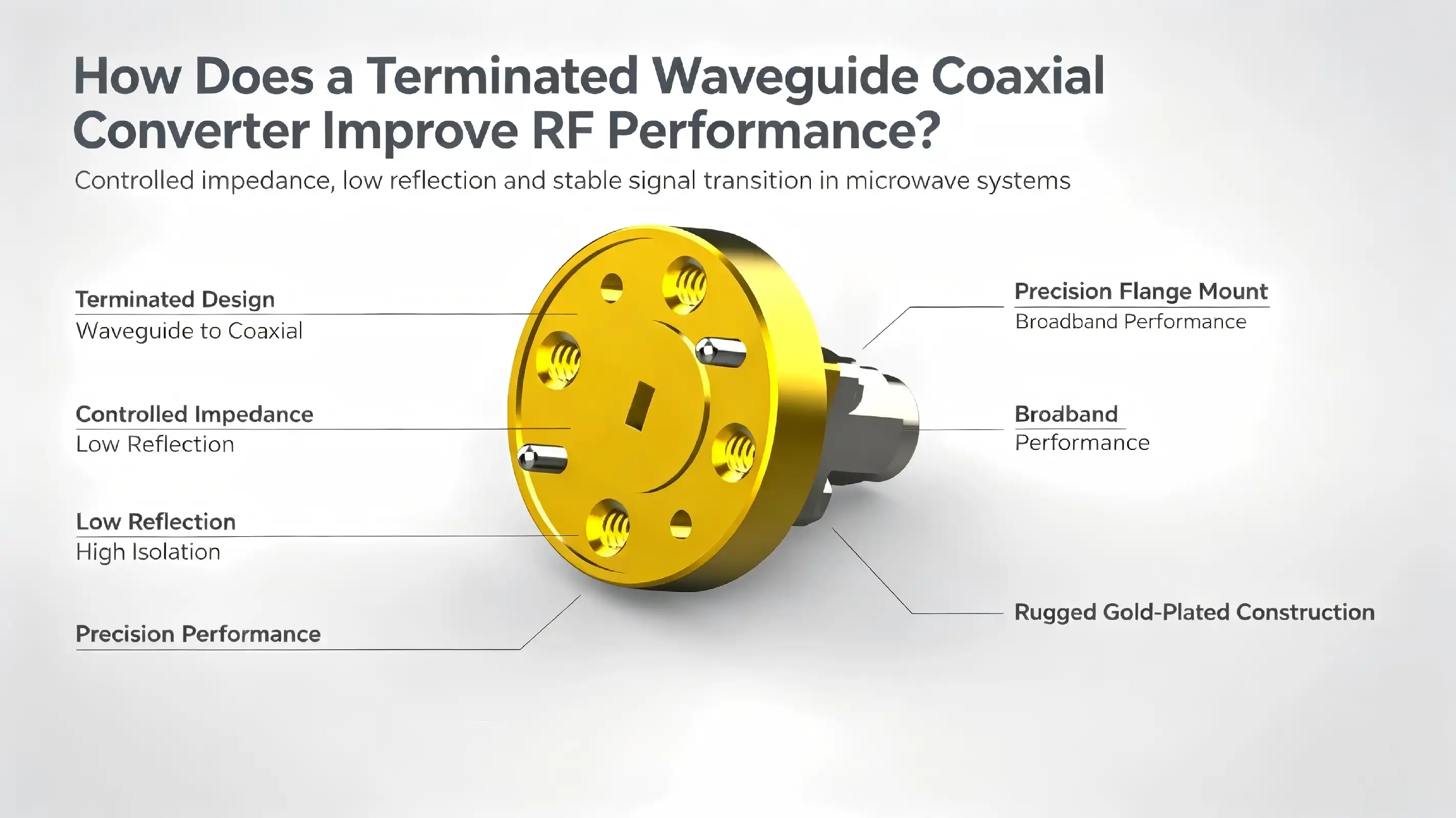
A terminated waveguide coaxial converter improves RF performance by eliminating signal reflections at the waveguide port, which directly reduces VSWR and prevents standing waves from destabilizing the transmission path. When a proper termination load absorbs residual energy rather than reflecting it back into the system, the entire signal chain becomes measurably cleaner. Engineers working in the 75–110 GHz W-band consistently report tighter measurement repeatability and lower noise floors when using terminated adapters during VNA calibration sequences. This single design choice can mean the difference between a reliable millimeter-wave link and a system plagued by interference artifacts. [1]

Understanding the Fundamentals of Terminated Waveguide Coaxial Converters
What Makes This Converter Different From Non-Terminated Variants
A waveguide-to-coaxial adapter literally connects two very different ways of sending signals: the coaxial line carries TEM mode data, and the hollow rectangular waveguide sends energy in the TE mode. Any unused port that isn't terminated will randomly send out or reflect energy. A terminated design builds an absorptive load right into the assembly. This blocks the signal path and keeps unwanted energy from damaging circuitry next to it. Because of this choice in structure, ended adapters are most common in precision test settings where exact measurements are required.
This model we're looking at has a 1.0 mm male coaxial interface and a WR10 waveguide end-launch port that works with UG-387/U-Mod spherical flanges. The end-launch shape sends signals along the axial direction, which is very different from orthogonal side-launch designs. Inside, the matching network is made up of an impedance-matching block and a matching projection. Some models go even further and add a multi-stage matching network that makes the change from the 50 Ω coaxial system to the WR10 waveguide equivalent impedance of about 50 Ω smooth. The end result was a standard VSWR of 1.5 and an insertion loss of 1 dB between 75 and 110 GHz. [2]
Material Choices That Sustain Millimeter-Wave Integrity
When millimetre waves are present, the choice of material is not just for looks; it is essential for performance. The main body is made of gold-plated brass, which is both easy to work with and good at conducting electricity. The inner circuit is made of gold-plated beryllium copper, which was picked because it is flexible and has low contact resistance. Passivated stainless steel makes up the outer wire, and polyetherimide (PEI) is used as the dielectric layer. PEI is a high-temperature material that has stable dielectric properties from -20 °C to +50 °C for operation and from -55 °C to +125 °C for storage. [3]
How Termination Enhances RF Performance: Technical Insights
Reducing VSWR and Suppressing Standing Waves
When mirrored energy stacks on top of the incoming wave, standing waves form. These waves create voltage highs and lows along the transmission line. When a waveguide adapter is not terminated, the open port reflects almost all of the energy that hits it. This can cause VSWR values that are higher than 2.0, based on the frequency. A terminated waveguide coaxial converter takes in that extra power and keeps the VSWR at or below 1.5, which is a specification limit that most precise RF systems need to keep their calibration accurate.
These benefits directly lead to improvements in data clarity that can be measured:
- Lower noise figure: Reduced reflections mean fewer spurious signal interactions at the detector or receiver input, lowering the system noise floor by a measurable margin during W-band device characterization.
- Improved isolation: The absorptive termination attenuates backward-traveling waves, increasing port-to-port isolation and reducing cross-talk in multi-channel test setups.
- Sustained stability under thermal stress: Because PEI maintains consistent dielectric properties and gold-plated beryllium copper resists micro-creep at elevated temperatures, the electrical performance remains stable across the rated operational range rather than drifting as the device heats up.
Better isolation: The absorptive termination weakens waves that move backward. This makes port-to-port isolation better and lowers cross-talk in multi-channel test sets.

Comparing Terminated vs. Non-Terminated Waveguide Coaxial Converters
Because of these features, ended W-band adapters are necessary in places where signal integrity is the main design requirement. When a purchasing engineer tests parts for W-band infrastructure, they should use VSWR and insertion loss as primary factors, not as extras. [4]
Waveguide Coaxial Converters: Terminated vs. Non-Terminated Comparison
There is no right or wrong answer when it comes to choosing between terminated and non-terminated adapters. It always comes down to which one works best for the job.
Troubleshooting and Optimizing Use of Terminated Waveguide Coaxial Converters
Step-by-Step Diagnosis for Common RF Performance Issues
Troubleshooting and Making the Most of Terminated Waveguide Coaxial Converters:
- Verify torque compliance first: The WR10 flange requires 0.45 ± 0.02 Nm. Over-tightening distorts the precision-machined mating surface; under-tightening introduces air gaps that raise VSWR above 1.6.
- Inspect and clean interfaces: Use a dedicated RF cleaner with dust-free cotton swabs. Oxidation on gold-plated surfaces increases contact resistance measurably. When the gold layer shows visible wear, replace the component promptly.
- Run quarterly VNA verification: Measure VSWR and insertion loss every quarter. If VSWR exceeds 1.6 or insertion loss climbs beyond the rated 1 dB, disassemble and inspect the internal matching components for deformation.
- Observe storage protocols: Idle units should be capped with dust covers and stored between −20 °C and +60 °C with relative humidity ≤ 60 %.
There are three main reasons why performance drops in W-band transitions: interface contamination, mechanical damage from over-torqued flanges, and worn gold plating that makes contact resistance higher. Here is a step-by-step plan for finding and fixing these problems:
Conclusion
The terminated waveguide coaxial converter adapter 1.0mm plug to 1.0mm jack is a precision-needed part, not a common one. For testing millimetre waves, 5G/6G systems, aircraft RF systems, and wafer-level components, this cable is a must-have. It has a 50© coaxial design, a gold-plated beryllium copper center conductor, a passivated stainless steel outer body, and has been tested to work at 110 GHz. It is important to choose the right adapter from a reputable manufacturer that supports OEM customisation, provides traceable quality documentation, and ensures consistent mechanical reliability. This will protect both the accuracy of measurements and the long-term investment in infrastructure.
FAQ
1. Why is termination essential in waveguide-to-coaxial transitions?
Following these maintenance steps regularly will greatly increase the useful life of terminated waveguide adapters and protect the accuracy of systems that rely on them.
2. Can a non-terminated adapter substitute in precision test setups?
A terminated waveguide coaxial converter solves one of the biggest problems in designing millimeter-wave systems: the random reflection that damages signals at every port that isn't being used or isn't matched well. The WR10-to-1.0 mm adapter described here has VSWR ≤ 1.5 and insertion loss ≤ 1 dB across the entire 75–110 GHz band. This is made possible by careful material choice, multi-stage impedance matching, and a strong end-launch architecture. Picking a quality-certified terminated adapter is an important engineering choice that pays off throughout the whole system lifecycle, whether it's for testing 5G/6G infrastructure, making sure radars work in cars, or using radio astronomy equipment. [6]

Partner With Chuangyu for Precision Millimeter-Wave Solutions
Terminated waveguide coaxial converter in the 5G, military, semiconductor, and medical fields accepts Chuangyu's verified Coaxial adapter 1.0mm plug to 1.0mm jack options. If you're looking for a top-quality Coaxial adapter 1.0mm plug to 1.0mm jack, Chuangyu has been making RF connectors for almost 20 years and can make more than 500,000 of them every year. They also offer full OEM customisation support. You can look at all of our products at cymicrowave.com or email our expert team at chuangyuwz01@cymicrowave.com to get a price or talk about the details of your project.
References
1. Pozar, D. M. Microwave Engineering, 4th ed. Wiley, 2011. Chapter 7 covers waveguide-to-coaxial transitions and impedance matching theory. https://www.wiley.com/en-us/Microwave+Engineering%2C+4th+Edition-p-9780470631553
2. IEEE Standard 1785.1-2012, IEEE Standard for Rectangular Metallic Waveguides and Their Interfaces for Frequencies of 110 GHz and Above. IEEE, 2012. https://standards.ieee.org/ieee/1785.1/3757/
3. National Institute of Standards and Technology (NIST). "Millimeter-Wave Connector and Adapter Characterization." Journal of Research of NIST, 2005. https://nvlpubs.nist.gov/nistpubs/jres/110/3/j110-3che.pdf
4. Hiebel, M. Fundamentals of Vector Network Analysis. Rohde & Schwarz, 2011. Section on W-band calibration standards. https://www.rohde-schwarz.com/us/products/test-and-measurement/network-analyzers/fundamentals-of-vector-network-analysis_230776.html
5. Agilent Technologies (Keysight). Specifying Calibration Standards and Kits for the PNA Series Network Analyzers. Application Note 1287-11, 2011. https://www.keysight.com/us/en/assets/7018-01375/application-notes/5989-4840.pdf
6. Virginia Diodes Inc. "WR10 Waveguide Products and Test Accessories." Product Application Notes, 2020. https://www.virginiadiodes.com/wr10
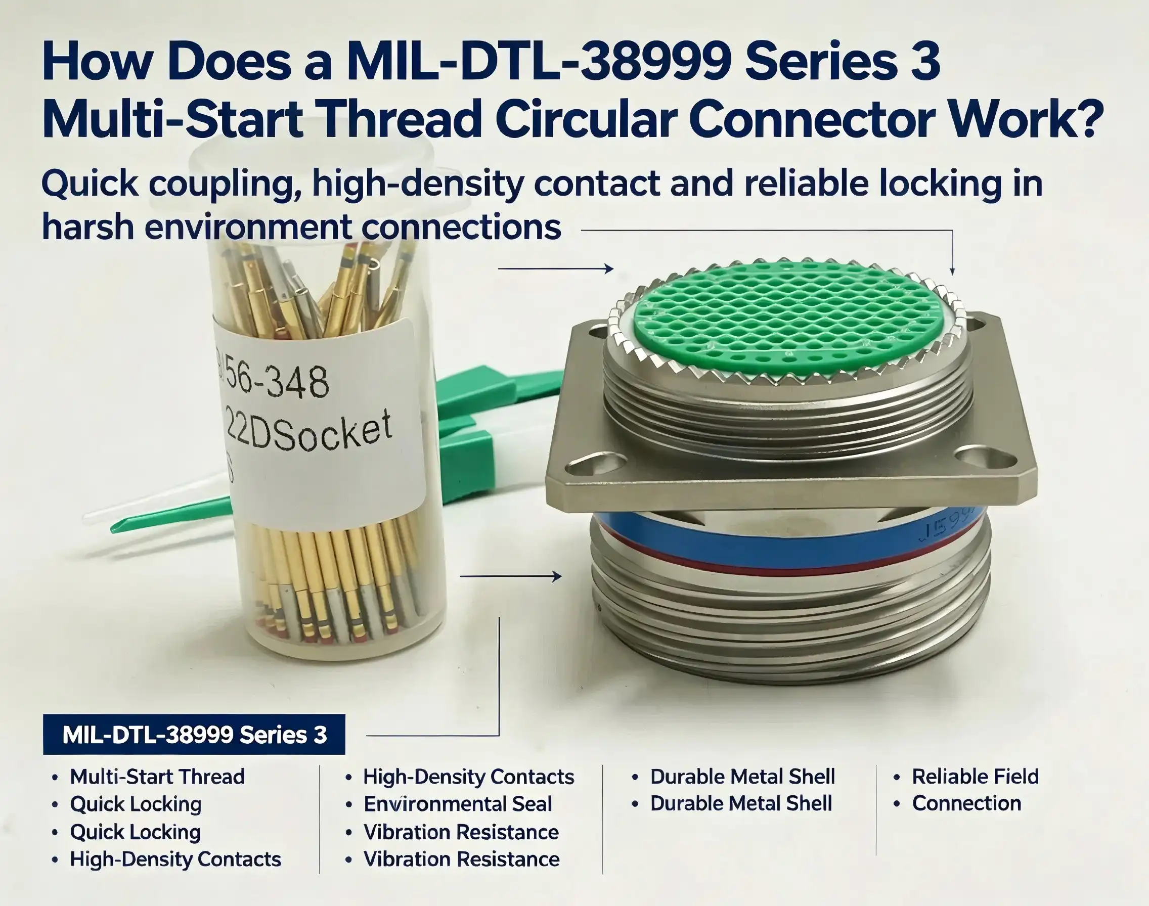
A MIL-DTL-38999 Series 3 Multi-Start Thread Circular Connector works by engaging a triple-lead threaded coupling mechanism that locks the plug and receptacle together in roughly one-third of a turn. Combined with a spring-loaded detent pawl, this self-locking design resists accidental disconnection under continuous vibration or shock. The connector's gold-plated copper alloy contacts, fluorosilicone seals, and conductive spring shielding work together to maintain signal integrity, power delivery, and environmental protection simultaneously—making it one of the most widely specified circular connectors in aerospace, defense, and industrial automation.

Introduction to MIL-DTL-38999 Series 3 Multi-Start Thread Circular Connectors
The MIL-DTL-38999 Series 3 Multi-Start Thread Circular connector is always at the top of the list when engineers and procurement managers are looking for a circular connection that strikes a good mix between speed, security, and durability. According to the MIL-DTL-38999 military performance standard, "Series 3" connectors have a triple-lead, self-locking threaded coupling, which works better than the bayonet coupling of Series 1 and the single-start thread of older designs.
The idea of a multi-start thread cuts mating time by a huge amount. The connector engages fully in about 120° of rotation instead of several full turns because the three thread starts are spread out evenly around the barrel. This is very important on a production line or during field repair, where technicians may have to work in tight areas or while wearing gloves.
Why Series 3 Is the Preferred Choice in Demanding Applications
Adoption data from the industry backs up the image. The IPC cites IHS Markit connection market data as saying that MIL-DTL-38999 Series III connectors make up the majority of new military connector designs. This is because they can connect and seal better than older MIL-C-5015 circular connectors, which means they can be used more quickly. [1]
Understanding the Design and Operation of Series 3 Multi-Start Thread Connectors
The tech behind this family of MIL-DTL-38999 Series 3 Multi-Start Thread Circular Connectors is worth looking into more closely. Three interconnected subsystems—mechanical coupling, electrical contact, and environmental sealing—work together to meet the requirements for reliability.
Mechanical Structure and Coupling Mechanics
With its self-locking triple-lead thread and detent pawl, the mated connection stays in place even in 300G shock-resistant settings. You can choose an aluminium alloy housing, a stainless steel housing, or an advanced composite housing. Composite-shell versions can be plugged in and out up to 1,500 times, which is a lot longer than the usual 500 times for aluminium housings. A Scoop-Proof keying system makes sure that pins and holes don't touch during blind-mate insertions, which keeps damage from happening when they aren't lined up correctly.
Electrical Contact Performance
The contacts are made of a copper alloy that has been plated with gold for at least 50 microinches. They can be crimped, soldered, or used to connect PCB tails. Standard configurations can hold up to 128 contacts, while high-density designs can hold up to 187. The current ratings are high: 12 AWG contacts can handle up to 46 A continuously, and 12 AWG contacts can handle up to 23 A continuously. These ratings meet the needs for both data and power distribution in a single shell.
Sealing and EMI Shielding
Fluorosilicone O-rings and back grommets work together to make the interface waterproof to IP67 standards, keeping it safe during short immersions. Conductive spring fingers between mated housings create electromagnetic shielding that is more than 90 dB effective at 100 MHz and still more than 65 dB effective at 10 GHz. This is an important shielding profile for platforms that work near high-power RF emitters. [2]
The MIL-DTL-38999 Series 3 Multi-Start Thread Circular Connector is not just a bunch of separate parts, but a fully combined answer thanks to these three subsystems.
Comparing MIL-DTL-38999 Series 3 with Other Connector Series and Types
Knowing where Series 3 fits in the bigger picture of connectors helps procurement managers wisely spend their money.
- Series 1 (Bayonet Coupling): Offers rapid quarter-turn mating but lacks the positive self-locking detent of Series 3. It is adequate for moderate-vibration environments but can experience unintentional decoupling under sustained dynamic loading—a limitation documented in NASA connector qualification reports. [3]
- Series 2 (Breech-Lock Coupling): Provides a compact profile favored in space-constrained enclosures, yet the non-self-locking mechanism demands secondary retention features in high-vibration installations.
- Single-Start Thread Connectors (e.g., MIL-C-5015): Require multiple rotations to mate fully. Engagement time is longer, and the thread is more susceptible to cross-threading under misaligned blind-mate conditions. MIL-C-5015 also lacks the structured Scoop-Proof feature standard in Series 3.
Because of this, the MIL-DTL-38999 Series 3 Multi-Start Thread Circular Connector performs better than Series 1 and Series 2 in situations where there is a lot of shaking, EMI, and thick contact counts. The trade-off is a slightly higher unit cost, which is usually balanced out by less work needed for installation and longer periods between repair visits.

Applications, Durability, and Performance Characteristics
The connector's claims in three main areas are backed up by facts from real-world deployments.
Aerospace platforms, like aeroplane electronics, satellite communication units, and UAV flight control assemblies, need to be able to work in temperatures ranging from -65 °C to +200 °C and handle 300G shock pulses. The Series 3 connector meets both standards without any downsizing, as shown in qualification test reports that are made public under MIL-DTL-38999 revision D [4].
Chemical exposure problems can happen with military equipment on land and at sea that can't be solved by designs that are only mechanical. Shipboard radar housings, missile guidance interfaces, and tactical radio terminals must be able to handle up to 2,000 hours of salt spray, contact with MIL-PRF-5606 hydraulic fluid, and immersion in JP-8 aviation fuel. Shell coatings are chosen based on this: black zinc-nickel plating protects against salt spray for 500 hours, making it ideal for coastal installations; nickel-PTFE coatings keep their shape at 200 °C for long periods of time.
There are different kinds of stress in industrial and medical settings. High-end robotics articulation joints move the connection thousands of times a year; medical imaging systems need shielding that doesn't mess up sensitive gradient signals; and marine research tools have to deal with biofouling and hydrostatic pressure. In this case, the anti-vibration locking and high-density contact layouts (up to 187 positions) meet needs that general-purpose circular connectors just can't.
Usage and Installation Best Practices
If you place the connection correctly, it will last as long as it is supposed to. To fully contact the connection during thread coupling, turn it around one full turn; overtightening will remove the self-locking pawl. If you check the key's position before axial insertion in blind-mate situations, you can keep the contact from getting damaged even if you can't see the mating face. For panel-mount receptacles to sit flush with the mounting surface, they need a matched back shell for strain relief. This keeps tensile loads from reaching the contact terminations.
Maintenance and Inspection Schedule
The industry recommends that inspections happen every three months. Contact resistance should be 9 milliohms or less; numbers above this level mean that there is rust or mechanical wear. Thread surfaces that show stress or galling need to be replaced right away. Isopropyl alcohol on a lint-free swab can be used to clean the contacts properly, and a dry lint-free cloth can be used to clean the shell. Solvents that are acidic or chlorinated can damage fluorosilicone seals and are not allowed at all. Standard-shell connectors need to be re-qualified for electrical performance every 500 joining cycles. Composite-shell connectors can be used for up to 1,500 cycles before they need to be re-qualified.
Procurement Considerations for MIL-DTL-38999 Series 3 Connectors
Total acquisition cost is more than just the unit price because of a number of factors. Choosing the right shell material, contact density, coating specifications, and backshell design can all affect the cost in their own ways. If buyers only buy from authorised outlets, they are less likely to get fakes. This is a known issue in the military connector supply chain that was brought up in a 2022 DLA traceability report. [5]
It is legal and normal to customise things. OEM programs often ask for non-standard contact layouts, keyway placements that are unique to the program, or mixed power-and-signal layouts that fit inside the same shell. Lead times for standard catalogue items are usually two to six weeks. For custom configurations, they can be eight to fourteen weeks, depending on how long the tools need to be made. The buyer's audit trail is safe if they ask for a Certificate of Conformance (CoC) and traceability documentation at the time of order.
Conclusion
The MIL-DTL-38999 Series 3 Multi-Start Thread Circular Connector is the best at what it does because it has fast triple-lead mating, self-locking vibration resistance, IP67 closing, and EMI protection that is better than 65 dB at 10 GHz. Service life can go up to 1,500 rounds with composite-shell versions, and Scoop-Proof keying keeps high-density contact arrays safe during blind mating. This connector family has measurable performance advantages that justify its place in demanding procurement programs, whether it's for a UAV avionics bay, a shipborne radar console, or a surgical imaging system.
FAQ
1. How much faster does a multi-start thread connector mate compared to a single-start thread?
A single-start thread needs at least 360° of rotation to fully engage, while a triple-lead thread only needs about 120°. This difference cuts down on the time it takes to make each link by a large amount in high-cycle assembly settings.
2. Can Series 3 connectors survive underwater immersion?
Yes. The fluorosilicone O-ring and rear grommet work together to get IP67 certification. This means that the connector can be submerged in water for 30 minutes at a depth of 1 meter without getting wet. Extra potting is recommended for long-term underwater depths.
3. How do I verify that a Series 3 connector is not counterfeit?
Ask for a Certificate of Conformance, a manufacturer's lot tracking number, and markings that can be compared to the Defence Logistics Agency's original MIL-DTL-38999 qualified products list (QPL). [6]
4. What is the maximum contact count available?
Up to 128 connections can be used in standard high-density designs. Specialised high-density shells can fit up to 187 contacts inside the same outer diameter.
5. Which shell coating suits a high-temperature industrial oven environment?
Nickel-PTFE coating can work continuously at 200 °C and doesn't react chemically with oils that are often used in industrial heating equipment.

Partner with Chuangyu — Your Trusted MIL-DTL-38999 Series 3 Multi-Start Thread Circular Connector Supplier
Chuangyu makes precision RF wire assemblies, millimeter-wave parts up to 110 GHz, and special test tools that all meet international quality standards. They also offer approved MIL-DTL-38999 Series 3 Multi-Start Thread Circular Connectors. Our engineering team can help OEMs with customisation, fast prototyping, and full paperwork for tracking. You can email us at chuangyuwz01@cymicrowave.com to get a price or look through our catalogue of approved products.
References
1. IHS Markit / IPC. Military Connector Market Analysis and Technology Trends. 2021. https://www.ipc.org/ipc-white-paper-military-connector-market
2. MIL-DTL-38999D. Detail Specification: Connectors, Electrical, Circular, Miniature, High Density, Quick Disconnect (Bayonet, Threaded, and Breech Coupling), Environment Resistant, Removable Crimp and Hermetic Solder Contacts. Defense Logistics Agency, 2018. https://quicksearch.dla.mil/qsDocDetails.aspx?ident_number=35171
3. NASA Technical Standards Program. Electrical Connector Selection and Application Guidelines (NASA-STD-8739.4). 2020. https://standards.nasa.gov/standard/nasa/nasa-std-87394
4. SAE International. Circular Electrical Connectors: Design and Test Requirements (AS50881). 2019. https://www.sae.org/standards/content/as50881/
5. Defense Logistics Agency. Counterfeit Parts Prevention and Traceability Audit Report. 2022. https://www.dla.mil/AboutDLA/News/NewsArticleView/Article/2922000/
6. Defense Logistics Agency Qualified Products Database. QPL-38999 Series III Approved Manufacturers List. 2023. https://landandmaritime.dla.mil/Programs/Qualified-Products-Database/
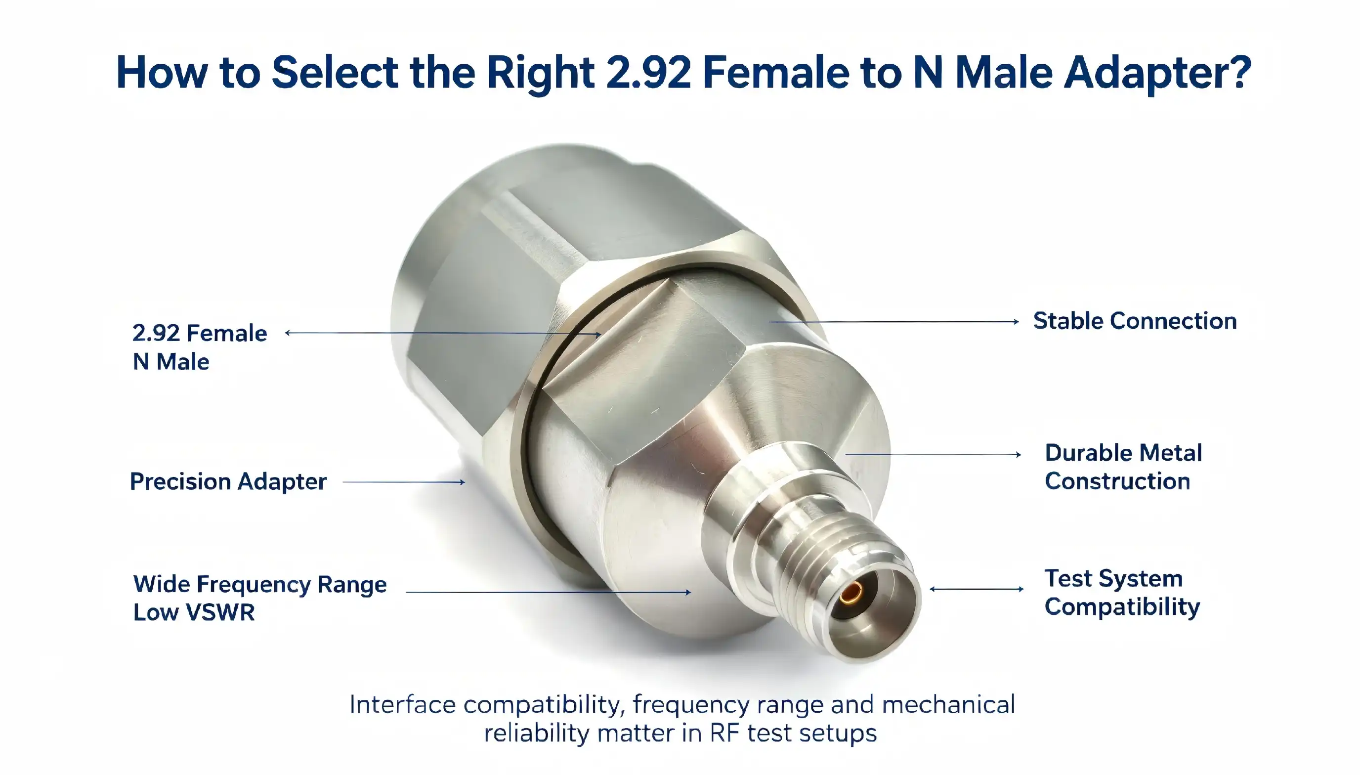
Selecting the right 2.92 female to N male adapter requires evaluating four core dimensions: operating frequency range, VSWR performance, material construction, and mechanical compatibility. This cross-series adapter bridges a 2.92mm (K-type) female interface with an N male connector, enabling signal relay between millimeter-wave and standard microwave equipment. A well-specified adapter should cover DC to 18 GHz with VSWR ≤1.25, maintain 50Ω impedance, and withstand ≥500 mating cycles. Procurement engineers should verify torque requirements, connector gender compatibility, and environmental ratings before finalizing supplier selection.

What Is a 2.92 Female to N Male Adapter?
A precision coaxial transition part called the 2.92 female to N male adapter is used to connect 2.92mm (K connection) receiving equipment to N-type transmission equipment. It fixes the physical and electrical problems that these two different interface standards have with each other in a small, tough body.
Structural Features and Material Construction
Both ends of this adapter are cross-series, with a 2.92mm female socket on one end and a N male pin on the other. The outer conductor is made of passivated stainless steel, which makes it very strong and resistant to corrosion. The inner wire is made of beryllium copper that has been covered with gold. This makes sure that high-frequency signals are sent with little loss. Polytetrafluoroethylene (PTFE) is used as the insulating medium. It has stable dielectric properties and makes sure that the 50Ω impedance matching stays the same throughout the operating range.
High-Frequency Electrical Performance
This 2.92 female to N male adapter works from DC to 18 GHz and has a VSWR of ≒1.25. It also has low insertion loss across the whole frequency range. Because of these numbers, it can be used for testing 5G base stations, satellite communication terminals, radar systems, and lab vector network analysers. The N male connector is the standard for microwaves, and the 2.92mm female socket can hold millimeter-wave equipment.
Critical Factors When Selecting a 2.92mm K-Type to N Male Adapter
Picking between adapters that look the same on paper can have a big effect on how well the system works. The following selection criteria are based on what procurement managers and experienced RF hardware engineers always put first.
When engineers write specifications, these are the main technical factors they look at:
- Frequency headroom: Although the operating frequency is rated at DC–18 GHz, confirm your system's actual upper frequency limit and select an adapter with at least 20% margin above your peak operating frequency to prevent degradation at band edges.
- VSWR and insertion loss: A VSWR ≤1.25 is the benchmark for low-reflection performance in precision test setups. Insertion loss specifications must be confirmed at your highest operating frequency, not just at DC or low microwave bands.
- Mechanical torque compliance: The 2.92mm end requires 0.8–1.1 Nm connection torque, while the N-male end requires 2.0–2.5 Nm. Deviating from these values causes connector deformation and irreversible signal degradation.
- Environmental durability: Passivated stainless steel offers superior corrosion resistance in humid or chemically active environments compared to standard brass. For outdoor RF installations or medical-grade labs, this distinction matters considerably.
When it comes to accuracy test sets, a VSWR of less than 1.25 is considered to have low reflection. You need to make sure that the insertion loss specs are correct at your highest operating frequency, not just at DC or low microwave bands.

Comparing Market Options for 2.92 to N-Type Adapters
Durability in harsh environments: Passivated stainless steel is better than regular brass at resisting rust in wet or chemically active places. This difference is very important for medical-grade labs or open RF systems.
What Sets Chuangyu's Adapter Apart
Amphenol, Pasternack, HUBER+SUHNER, Rosenberger, and Radiall are some of the top makers of 2.92 female to N male adapters. Their products have different levels of performance, lead times, and mechanical construction. Before making large orders, procurement teams usually look at insertion loss curves, frequency coverage data sheets, and verified mating cycle scores when they look at choices from these names.
How to Properly Install, Maintain, and Troubleshoot Your Adapter
The 2.92 female to N male adapter from Chuangyu is made for high-cycle test settings. This adapter has gold-plated beryllium copper inner conductors, PTFE insulation, and can be plugged in and pulled out up to 500 times. Its electrical performance stays stable during demanding test sequences. Chuangyu's adapter is different from most commercial ones because it was made to meet the needs of 5G infrastructure tests, satellite link validation, and spectrum research platforms. The performance of VSWR ≤1.25 stays the same from DC to 18 GHz, not just at spot frequencies.
Usage Specifications and Pre-Use Inspection
Both the adapter and the instruments that are joined are protected when they are installed correctly. RF plug application notes say that one of the main reasons for unexpected VSWR spikes in test settings is bad handling. [4]
Maintenance and Care
Before you connect the adapter, check to see if the outer wire has changed shape and that the gold finish isn't peeling or oxidising. Both the female socket and the male pin must be clean and not broken in any way. Any problem that can be seen needs to be replaced right away, because using a faulty adapter could damage the port that connects to the instrument.
Use a measured torque wrench to connect the 2.92mm female end at 0.8–1.1 Nm. Make the N male end tighter by 2.0 to 2.5 Nm. Misalignment of the center pin is most often caused by inserting it at an angle or hand-tightening it too much. The frequency of the test signal must stay between DC and 18 GHz, and the power must not go over the stated value. Do high-frequency tests inside a shielded enclosure to keep nearby equipment from interfering with the signals.
Procurement Tips for Buying RF Adapters Efficiently
Use a special RF swab that has been wet with anhydrous alcohol to clean the interface. This gets rid of the surface oxides, dust, and biological leftovers that make insertion loss worse over time. Put the adapter away in a dry, covered container that stays between -10°C and 40°C and has a relative humidity of less than 60% RH.
If the VSWR suddenly goes up or the signal attenuation seems off while testing, you should remove the adapter and look at the mating surfaces. Do not keep testing with a unit that you think is broken. If you use a broken K connector to N male adapter, it could damage the instrument port, which would cost a lot more to fix than to buy a new one.
Conclusion
When looking for 2.92 female to N male adapters, B2B procurement teams should make sure that suppliers meet three strict requirements: they must be able to track products, offer expert help, and provide verified performance data. Price commitments and lead times for large orders are important, but they shouldn't come before material and electrical validation.
FAQ
1. What is the maximum operating frequency of a 2.92 female to N male adapter?
To choose the correct 2.92mm female to N male adapter, you need to follow a structured process: check the frequency headroom, the VSWR and insertion loss data, the torque requirements, and the quality infrastructure of the supplier. This adapter is designed to work in places where signal integrity can't be compromised, like 5G base station test rigs, radar validation benches, and platforms for integrating satellite communication. Everything about it, from the gold-plated beryllium copper wires to the PTFE insulation, helps it work well for hundreds of mating rounds. Long-term results are always better when purchasing decisions are based on verified technical data instead of just catalogue price.

Partner With Chuangyu for Precision RF Connectivity Solutions
With nearly 20 years of precision manufacturing experience, Chuangyu's 1.5mm needle standard stroke photovoltaic test probe satisfies strict production and R&D standards. As a reliable company that makes 1.5mm needle standard stroke photovoltaic test probes, we can make unique designs, use certified materials, 2.92 female-to-N male adapter, and make one million test probes every year. To get specs or talk about your application needs, email our engineering team at chuangyuwz01@cymicrowave.com.
References
1. Amphenol RF. RF Connector Technical Reference Guide. Amphenol Corporation, 2022. https://www.amphenolrf.com/technical-resources
2. Pasternack Enterprises. Coaxial Connector Torque Specifications and Best Practices. Pasternack, 2021. https://www.pasternack.com/t-connector-torque-specifications.aspx
3. IEEE Standards Association. IEEE Std 287-2007: Standard for Precision Coaxial Connectors at Frequencies up to 110 GHz. IEEE, 2007. https://standards.ieee.org/ieee/287/3557/
4. Keysight Technologies. Coaxial Connector Care and Maintenance — Application Note 326. Keysight, 2020. https://www.keysight.com/us/en/assets/7018-06806/application-notes/5952-1087.pdf
5. Microwave Journal. RF Connector Material Selection for High-Frequency Applications. Microwave Journal, 2023. https://www.microwavejournal.com/articles/rf-connector-material-selection
6. Mini-Circuits. Understanding VSWR and Return Loss in RF Systems. Mini-Circuits Technical Blog, 2022. https://www.minicircuits.com/pages/pdfs/VSWR.pdf
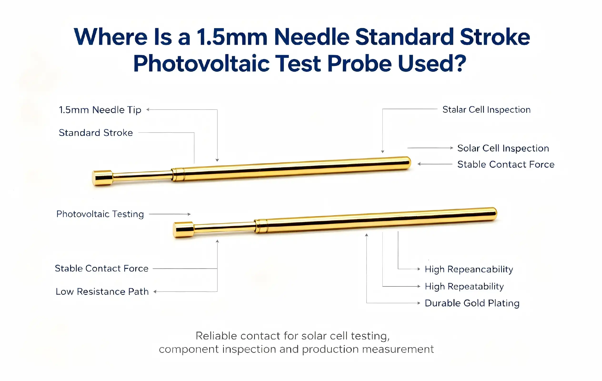
The 1.5mm needle sstandard-strokephotovoltaic test probe is primarily used in solar cell electrical performance testing — specifically for I-V characteristic measurement, quality control inspection, and R&D validation on high-efficiency cell technologies including PERC, TOPCon, and HJT. Its 1.5mm flat-contact needle tip is engineered to interface precisely with fine grid lines (≤50μm width) without damaging delicate cell surfaces. In photovoltaic produ< 50 μm lines and research laboratories, this photovoltaic test probe delivers stable, repeatable contact performance across millions of test cycles, making it a mission-critical component in modern solar manufacturing and new energy development workflows.

What Makes the 1.5mm Needle Standard Stroke Photovoltaic Test Probe Distinct
When I look at precision test probes for solar uses, the 1.5mm needle standard stroke photovoltaic test probe stands out right away because of its unique structural design. It's easier for purchase managers and hardware experts to choose the right tool when they know how it's built.
Needle Design and Contact Geometry
The probe has a flat contact tip with a diameter of 1.5 mm that was made to work with the fine grid line structures found in modern photovoltaic cells. This shape spreads the contact force out equally, which lowers the mechanical stress on the fine silver paste grid lines (≤< 50 μmpitch) while keeping the low-resistance interface stable. The flat contact lowers the chance of microcracks compared to sharp-tip options. This is very important in high-efficiency cell tests because hidden cracks can ruin yield data and long-term cell reliability [1].
Material Composition and Coating
The needle tube is made of gold-plated phosphor bronze, which is very good at conducting electricity and is also very strong. The needle rod is made of gold-plated quenched steel, which makes it hard and resistant to wear even after being compressed many times. The internal spring is made of precisely wound piano stainless steel wire, which makes sure that the spring force stays the same (about 200gf) over the life of the product. Putting gold finishing on both contact surfaces lowers contact resistance and stops oxidation, which is a big plus in solar manufacturing facilities, which tend to have high humidity levels [2].
Telescopic Stroke Mechanism
The internal spring moves the needle rod through a 5–6 mm travel-guide structure, which can accommodate cells with different thicknesses without the need for manual adjustments. The piston-guide design lowers friction on the side, which protects both the probe and the surface of the cell. This engineering gives a guarantyd mechanical lifetime of more than 1,000,000 insertion cycles, which has a direct effect on cost-per-test estimates in high-volume production environments.
The 1.5mm needle photovoltaic probe is a high-durability, low-damage way to test solar cells precisely because of these structural traits. Once you understand this base, choosing an application is a lot easier.

Application Areas of the 1.5basiseedle Standard Stroke Photovoltaic Test Probe
This type of tool can be used for a lot more than just one step in the production process. The 1.5mm needle standard stroke photovoltaic test probe is most effective in the following circumstances:
- High-efficiency cell I-V testing: The probe conducts current-voltage characteristic measurements on PERC, TOPCon, and HJT cells. With grid line widths shrinking below 50μm in next-generation designs, precise spatial contact is essential for accurate efficiency and fill-factor data collection. A single misaligned or worn probe can skew conversion efficiency readings by several tenths of a percent — a significant error in quality-controlled production [3].
- Photovoltaic R&D laboratory validation: Research teams working on perovskite solar cells and tandem cell architectures use this probe for non-destructive electrical characterization of small-area samples. The flat contact tip preserves fragile experimental layer stacks while collecting reliable performance data that informs material selection and structural optimization.
- Automated test equipment (ATE) integration: In inline solar cell sorters and flash testers, the 1.5mm needle probe integrates into multi-probe fixtures that contact multiple grid lines simultaneously. Its ≥1,000,000-cycle lifespan aligns with the throughput demands of industrial ATE environments, where probe replacement downtime directly affects line output.
- Quality control and incoming inspection: Module manufacturers and cell suppliers use this probe in incoming quality inspection stations to verify electrical consistency before lamination. Early detection of underperforming cells at this stage prevents downstream yield losses.
In addition to these main solar uses, the same probe construction is also used for checking semiconductors and inspecting electronics where small-pitch contact points and controlled insertion force are needed. This shows how versatile its precise design is.
How to Choose the Right Photovoltaic Test Probe
To choose the right probe, you have to make sure that the mechanical and electrical requirements match the test scenario. Applications requiring fine grid lines and controlled contact pressure are well suited to the 1.5mm needle standard stroke photovoltaic test probe. A 2mm needle probe, on the other hstandard-stroke bus bars and main grid contacts that are bigger, as long as the contact area is big enough. In experimental cell studies, microprobes with a width of less than 1 mm are used on structures with very small pitches.
Besides checking the diameter, buying teams should also make sure that the parts are RoHS-compliant, make sure that the gold plating thickness meets the requirements, and ask sellers for written cycle-life test data. OEM qualification records and output certificates show that the manufacturing is consistent, which is needed for B2B sourcing at a high rate. When adding new probe models to existing test processes, responsive technical help and written guarantee terms lower the risk of buying them even more.
Procurement Tips for Sourcing Photovoltaic Test Probes
When you strategically source precision solar probes, you can balance the cost of each one against the total cost of ownership. Longer-lasting probes, like the 1.5mm needle standard stroke photovoltaic test probe's ≥1,000,000-cycle rate, don't need to be replaced as often and don't cause as much downtime, which is often a good reason to pay more per unit than lower-specification options.
When handling large orders, procurement budgets are kept safe by asking for sample batches to be tested in-house before committing to full volumes. Suppliers that do both needle machining and coating are usually able to offer tighter tolerances on dimensions and more consistent quality from lot to lot than distributors that only do assembly. Other things that set trusted 1.5mm needle photovoltaic test probe providers apart from commodity vendors are clear lead times, open minimum order quantities, and documented help after the sale [4].

Maintenance and Longevity of the 1.5mm Needle Standard Stroke Photovoltaic Test Probe
Proper handling directly increases the life of the probe and ensures the integrity of the test data. I suggest that these rules be followed the same way in both production and study settings.
Before using, check that the needle test claws are still in one piece, the gold finish is still intact, and the spring moves smoothly back and forth. Probes that have worn contact surfaces or test claws that aren't fully assembled need to be replaced right away because they give inaccurate readings of contact resistance, which changes data about how well cells are working.
Set up and contact pressure: Line up the probe vertically with the fine grid lines on the cell. The contact pressure has to stay within the spring force range, which is usually around 200gf. When there is too much force, grid lines can break ,or tiny cracks can form in the cell that make it less durable without being noticeable right away [5].
Cleaning instructions: Use a dust-free cloth wetted with solar cleaner or rubbing alcohol to wipe the needle tip clean before and after each test. This gets rid of the silver paste dust, oxides, and particles that build up over time and make the contact resistance higher. The needle surface should never be touched by hard tools.
Probes should be kept in a sealed, antistatic container at -10°C to 40°C and a humidity of ≤60% RH. If you store something for more than three months, check the spring's elasticity and the needle's internal stability on a regular basis to find early signs of wear and tear.
Anomaly response: changes in current or I-V curve profiles that aren't straight during tests because of probe error or wear. Stop testing right away, look at the probe, and fix the problem before starting again. Testing mistakes at this point lead to wrong cell performance classifications, which have expensive effects further down the line.
Conclusion
In the production of solar cells, approval of research and development, and quality control, the 1.5mm needle standard stroke photovoltaic test probe holds an exact and indispensable position. Its gold-plated material stack, flat-contact tip, and ≥1,000,000-cycle telescopic mechanism meet the needs of high-efficiency cell technologies with small grid designs. Choosing the right probe, getting it from a reputable maker, and following the right working procedures all directly affect the accuracy of tests and the consistency of operations. Teams working with PERC, TOPCon, HJT, or new perovskite technologies should buy tried-and-true solar probe options because they are technically sound and make good business sense.
FAQ
1. How does a 1.5mm needle standard stroke photovoltaic test probe differ from a micro test probe?
A photovoltaic test probe with a 1.5mm needle and a flat 1.5mm diameter contact tip works best with standard small grid lines (≤50μm) on industrial high-efficiency cells. For experimental or research-stage devices with very narrow pitch designs, micro test tools with diameters of less than a millimetre are used. The 1.5mm version has a more precise balance of contact area, which makes it better for testing on a larger scale where both accuracy and cycle durability are important.
2. Can this probe handle both PERC and TOPCon cell testing?
Yes. The flat contact shape and controlled spring force (≤< 200 gf work with the fine grid designs of both PERC and TOPCon cells without damaging the grid lines or creating tiny cracks that are hard to see. The stroke range of 5–6 mm also works with the slightly different cell sizes between these technologies.
3. Are custom configurations available for this photovoltaic test probe?
Manufacturers that are qualified can make customised probe solutions that include different lead wire configurations, stroke lengths, and tip shapes. You should give the supplier's engineering team detailed technical drawings and application parameters when looking for a 1.5mm needle standard stroke photovoltaic test probe with non-standard specs to make sure it will work.
4. How often should these probes be replaced in high-volume production?
With a proven mechanical life of ≥1,000,000 cycles when used correctly, the number of cycles between replacements depends on how many times the product is used each day. Regular checks before use and following contact pressure limits extend service life and reduce the number of unexpected replacements.

Partner with Chuangyu for Precision Photovoltaic Test Probes
With nearly 20 years of precision manufacturing experience, Chuangyu's 1.5mm needle standard stroke photovoltaic test probe satisfies strict production and R&D standards. As a reliable company that makes 1.5mm needle standard stroke photovoltaic test probes, we can make unique designs, use certified materials, and make one million test probes every year. To get specs or talk about your application needs, email our engineering team at chuangyuwz01@cymicrowave.com.
References
1. Fraunhofer Institute for Solar Energy Systems ISE. Solar Cell Efficiency Tables and Characterization Methods. Fraunhofer ISE, 2023. https://www.ise.fraunhofer.de/en/publications/studies/solar-cells-and-modules.html
2. IEC 60068-2-20. Environmental Testing – Part 2-20: Tests – Test T: Soldering. International Electrotechnical Commission, 2021. https://www.iec.ch/homepage
3. NREL (National Renewable Energy Laboratory). Best Research-Cell Efficiency Chart. U.S. Department of Energy, 2024. https://www.nrel.gov/pv/cell-efficiency.html
4. International Technology Roadmap for Photovoltaic (ITRPV). ITRPV 14th Edition 2023. VDMA Photovoltaic Equipment, 2023. https://www.vdma.org/en/viewer/-/v2article/render/67776702
5. Warta, W., & Glunz, S. W. "Advanced Characterization Techniques for Solar Cell Research and Production." Progress in Photovoltaics: Research and Applications, Wiley, 2022. https://onlinelibrary.wiley.com/journal/1099159x
6. PV Tech. Cell Technology Trends: PERC, TOPCon, and HJT Production Scaling. Solar Media Ltd., 2023. https://www.pv-tech.org/cell-technology-trends-perc-topcon-hjt
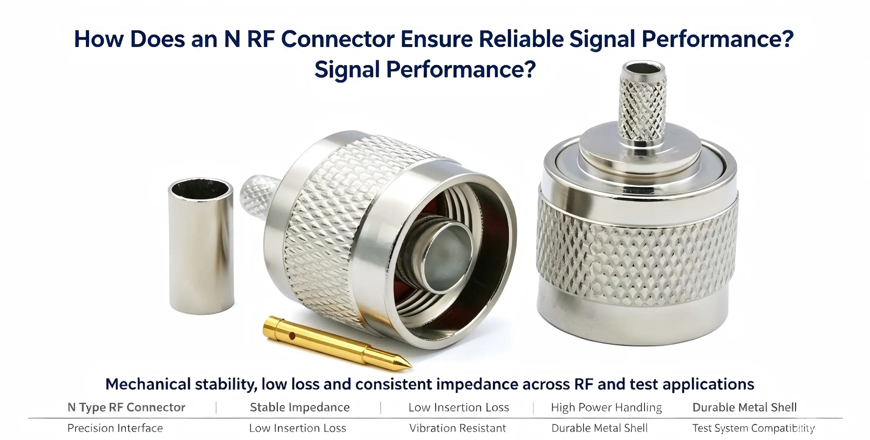
An N RF connector ensures reliable signal performance through a combination of precision mechanical design, high-quality materials, and strict electrical specifications. Built on a 5/8"-24UNEF threaded interface, it maintains stable impedance at 50Ω across DC to 11 GHz — with precision variants reaching 18 GHz. The gold-plated beryllium copper inner conductor keeps contact resistance at < 2 mΩ, minimizing signal attenuation. With VSWR ≤1.25, shielding effectiveness exceeding 90 dB, and IP67-rated weatherproofing, this coaxial connector delivers consistent performance in telecommunications, aerospace, and industrial testing environments where signal integrity cannot be compromised.

Understanding the Fundamentals of N RF Connectors
As a way to fix high-frequency signal loss in military transmission systems, Paul Neill created the N-type coaxial connector at Bell Laboratories in the 1940s. Even after many years, it is still an important part of current RF and radio infrastructure.
The socket has a characteristic impedance of 50, which means it works with most RF communication methods on the market today. A 75© version is also available, mostly for cable TV uses. However, the two can't be mechanically switched out. To avoid expensive mistakes, it's important to understand that difference before you buy something.
Core Technical Specifications
Standard N RF connectors work from DC to 11 GHz, and high-precision versions can work up to 18 GHz. Under normal circumstances, the VSWR stays ≤1.25, which means that there is very little signal bounce and the signal is perfectly intact. The 5/8"-24UNEF threaded coupling contact is very stable mechanically and can handle connection torques of 0.8 to 1.2 N·m. This range of torques locks the link securely enough to keep it from shaking without hurting the surfaces that touch each other inside.
Material Architecture
The base of the connector is made of brass or stainless steel, and the outside is plated with gold or nickel to make it electrically conductive and resistant to corrosion. The inner wire is gold-plated and made of beryllium copper or brass. This keeps the contact resistance at or below 2mΩ. That level of accuracy lowers signal loss directly at the contact surface, which is very important at microwave frequencies [1].
Key Performance Dimensions of N RF Connectors
Performance of an N-type connector can be judged in three main areas: how well it works electrically, how long it lasts mechanically, and how well it works in different environments.
These are the most important performance standards that procurement teams and design engineers should look at:
- Electrical Efficiency: With shielding effectiveness exceeding 90 dB, the N RF connector resists electromagnetic interference (EMI) effectively. When paired with LMR-400 cable, insertion loss measures approximately 0.18 dB/m at 1 GHz — a low-loss figure that makes it suitable for long cable runs in base stations and satellite ground systems [2].
- Power Handling: Paired with LMR-400, the rated power capacity reaches 300W at 2 GHz. This makes N-type coaxial connectors well-suited for high-power RF transmission scenarios where thermal management and signal stability are critical concerns.
- Mechanical Endurance: The mating cycle rating of ≥500 insertions supports repeated connect/disconnect operations in laboratory and field environments without degradation in contact performance.
- Environmental Range: Standard models operate between -40°C and +85°C. High-performance variants extend that range to -55°C and +125°C. With an optional waterproof kit, IP67 protection makes these connectors viable for outdoor deployments in all weather conditions.
These performance standards are based on real operating needs in a wide range of fields, from wireless base stations to industrial automation. These requirements can be used right away by any engineer who is making something for a harsh or high-frequency environment.
Installation Best Practices
The long-term performance of a connector depends a lot on how well it was installed. When crimping, use the tools that the maker recommends to make sure that the inner and outer wires of the cable are both compressed evenly. When gluing, be careful to keep the temperature under control. Too much heat can damage the gold plating and the polyethylene insulator, both of which can make the signal less reliable. Always use a measured torque wrench to make sure the torque is between 0.8 and 1.2 N·m [3].

Comparing N RF Connectors with Other RF Connector Types
In order to choose the right connector for a job, you need to know how the N-type compares to other options.
The SMA connector is smaller and can handle frequencies up to 18 GHz (some up to 26.5 GHz). This makes it useful for portable instruments and circuit boards. However, it can't handle as much power and isn't as durable as an N-type connection. If you need a base station or high-power radio broadcasting, the N-type coaxial connector is the better choice [4].
TNC connections are threaded and better than BNC connectors. They work up to 11–12 GHz and are more resistant to shaking. They have the same weatherproofing benefit as the N connector, but they are smaller and can't handle as much power. BNC connections can only handle 4 GHz and have a bayonet lock, which makes them quick to connect but not good for long-term microwave transfer or places with a lot of vibration.
N Connectors in 5G and Microwave Infrastructure
Low-PIM N-type connectors are specially made for installing 5G base stations, where passive intermodulation distortion has a direct effect on the quality of the network. These versions have toughened housings, low insertion loss (below 0.2 dB), and waterproof construction. These are all requirements for dense 5G antenna arrays that work outside. These specially designed versions work better than regular coaxial connections, making them a better choice for procurement teams looking to buy RF parts for next-generation wireless infrastructure.
Procurement and Sourcing Insights for N RF Connectors
It takes more than comparing datasheets to find high-quality N RF connectors on a large scale. Total project cost and delivery success are all affected by things like reliability, certification status, lead time, and the ability to make changes.
Amphenol, TE Connectivity, and Pasternack are some of the well-known global makers and sellers of N RF connectors. They offer a wide range of products that meet strict quality standards. It's just as important for OEM and ODM makers with non-standard needs to be able to get custom parts.
When choosing a N RF connector source, think about the following:
- Certification and Standards Compliance: Look for connectors that meet MIL-STD or equivalent international standards, confirming performance under defined environmental and electrical conditions.
- Custom Assembly Capability: Projects with unique cable lengths, termination types, or connector pairings benefit from suppliers who offer end-to-end assembly — not just off-the-shelf parts.
- Lead Time and Inventory: For high-volume procurement, confirm whether the supplier maintains stock for rapid fulfillment or requires production lead time that could affect project timelines.
Custom Assembly: Suppliers who offer end-to-end assembly, not just off-the-shelf parts, are better for projects that need custom wire lengths, termination types, or connector pairs.
Ensuring Long-Term Signal Performance: Best Practices and Case Studies
N-type connectors usually work with cables like LMR-400, RG8, RG213, and RG214 that are compatible. It is easy for these low-loss cables to meet the power and frequency requirements of the connection because they have copper-clad aluminium or pure copper center wires and tin-plated copper braid shielding.
Making sure signals work well for a long time: best practices and case studies
Maintenance and Inspection Protocol
In the lab, R&D engineers tested N RF connectors to connect network analysers and amplifiers. They found that VSWR readings stayed below 1.3 even after repeated measurement campaigns with the same amount of torque and scheduled inspection cycles [5]. This proved that the connector is mechanically repeatable.
Technology Trends
In high-cycle settings, check the mating areas every three months. Check the dielectric area for signs of gold coating wear, thread deformation, or debris buildup. Use isopropyl alcohol and lint-free cloths to clean surfaces that come into contact with things. If a connector has contact resistance above 5m© or is clearly deformed, it needs to be replaced. Regular upkeep of RF interconnects stops signal degradation from getting worse over time and leading to system-level breakdowns that can be measured.
Conclusion
New materials are being developed all the time, like advanced gold alloy plating formulas and precision-machined beryllium copper contacts, which are making N RF connectors last longer and handle higher frequencies. As 5G mmWave networks grow and test systems move toward higher frequencies, companies are making hybrid connections that combine the strength of N-type connectors with the frequency range of precision 2.92 mm or 2.4 mm connectors.
FAQ
1. Is an N-type connector suitable for 5G deployments?
From DC to 11 GHz, standard N RF connectors can work. Precision high-frequency versions make the results go up to 18 GHz. This range includes most wireless communication systems, such as 2G to 5G base stations, satellite links, and test tools for the lab.
2. What is the correct torque for installing an N RF connector?
Yes. In 5G base station infrastructure, low-PIM N RF connectors that are specially made are used a lot. Because they are waterproof up to IP67 and have ruggedised housings, they can work with outdoor radio systems that operate at 5G sub-6 GHz frequencies.
3. What cables are compatible with N-type coaxial connectors?
A calibrated torque wrench should be used to apply the suggested connection force of 0.8 to 1.2 N·m. Both too little and too much torque can damage the signal integrity. Too little torque can cause irregular contact, and too much torque can deform the inner wire or thread.
4. How does an N RF connector compare to an SMA connector?
LMR-400, RG8, RG213, and RG214 wires are all compatible. All of them are made with low-loss materials, copper-centered wires, and braided insulation that can handle high-power RF transmission.

Partner with Chuangyu for Precision N RF Connector Solutions
SMA connections are smaller, can handle higher frequencies, but not as much power. N-type plugs are better for outdoor infrastructure and high-power N RF connector systems because they are more mechanically tough, can handle more power, and are waterproof up to IP67.You can email us at chuangyuwz01@cymicrowave.com to get a price or look through our catalogue of approved products.
References
1. Pasternack Blog — What Is an RF Connector? Pasternack Enterprises, 2022. https://blog.pasternack.com/rf-connectors/what-is-an-rf-connector/
2. Times Microwave Systems — LMR-400 Coaxial Cable Datasheet and Loss Specifications. Times Microwave, 2021. https://www.timesmicrowave.com/products/lmr/lmr-400
3. IPC/WHMA-A-620 — Requirements and Acceptance for Cable and Wire Harness Assemblies. IPC Standards, 2017. https://www.ipc.org/ipc-whma-620
4. VCElink Technical Blog — RF Connector Types: SMA, BNC, TNC, N-Type Comparison. VCElink, 2023. https://www.vcelink.com/blogs/focus/rf-connectors
5. Keysight Technologies — Best Practices for RF and Microwave Connector Care and Use. Keysight Application Note, 2020. https://www.keysight.com/us/en/assets/7018-06840/application-notes/5992-1046.pdf
6. IEEE Microwave Magazine — Advances in Coaxial Connector Technology for 5G and Beyond. IEEE, 2022. https://ieeexplore.ieee.org/document/9782100
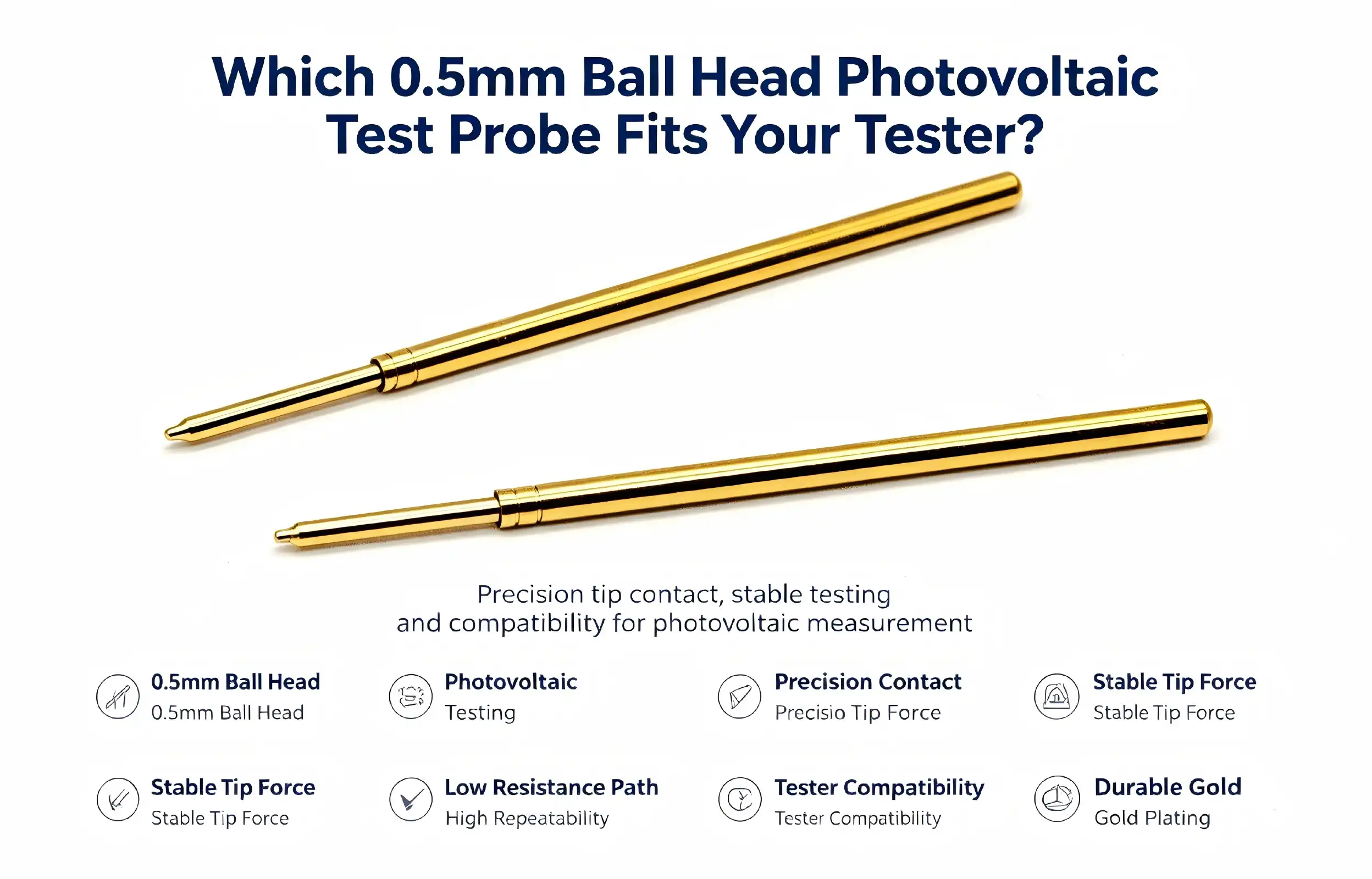
The choice of the suitable 0.5mm ball head photovoltaic test probe relies on the requirements of your testing equipment, the solar cell technology you are using, and your operating needs. The measurements for the BC, HJT, TOPCon, and perovskite cells need precision spherical contact tips to deal with ultra-fine grid lines without mechanical damage. Performance reliability is a function of compatibility with the electrical specifications of your tester, such as current capacity and contact resistance requirements. The probe of Shaanxi Chuangyu Electronic Technology uses a beryllium copper gold-plated structure and spring-loaded telescopic structure to ensure the stability of the electrode contact during the test cycle of more than 2 million times, and the resistance is less than 15mOhm, which is suitable for a photovoltaic test environment.


Understanding 0.5mm Ball Head Photovoltaic Test Probes
Photovoltaic testing demands precision tools that protect delicate solar cells while delivering accurate electrical measurements. The ball head test probe represents a specialized solution engineered specifically for this challenge. Understanding its design, construction, and operational principles helps procurement teams make informed decisions.
What Defines a Ball Head Test Probe
The spherical contact tip differentiates this probe from conventional needle-style probes. The contact pressure of a 0.5 mm diameter ball head is uniformly distributed to the grid lines of the solar cell, which avoids the stress concentration that may harm delicate structures. This design is crucial for evaluating next-generation solar technologies with ultra-fine grid patterns, with widths of 30 micrometres or less.
Chuangyu’s probe consists of 3 key material parts, including gold-plated phosphor bronze for the needle tube, gold-plated beryllium bronze for the needle rod, and piano stainless steel wire for the internal spring. This blend of materials guarantees superb conductivity, wear resistance, and corrosion protection for millions of test cycles. The gold-plating is mainly to provide uniform electrical performance. Gold prevents oxidation, which affects the quality of the contact over time.
Working Principle and Contact Mechanism
The telescoping design allows the probe to adjust to cells of different thicknesses and maintain constant contact pressure. A precise piston-guide mechanism lowers the friction of the piston during extension and retraction, which plays a role in the operational lifetime of the probe, reaching one million cycles. The built-in spring has a 5- 6 mm travel distance and can meet the varied substrate profile without manual modification.
The spherical tip is contacted with the electrode of the solar cell to provide a reliable electrical connection for the current and voltage measurements. The ball head design provides a fixed contact area that is repeatable over repeated tests as opposed to pointed probes, which may cause varying contact zones. This consistency has a direct translation to repeatability of measurement, which is so crucial in certifying manufacturing lots or in making research comparisons.
Technical Specifications and Compatibility
Correctly matching equipment is made easier by knowing electrical and mechanical ratings. Chuangyu’s photovoltaic test probe is designed for operation at temperatures from -45°C to +80°C, enabling testing in controlled laboratory settings and on manufacturing floors. 7A current capacity to support high-efficiency cell testing techniques requiring strong electrical performance.
Specifications of the contact resistance directly affect the measurement accuracy. The probe has a resistance of less than 15mOhm over its operating life; therefore, the voltage drop is small during the I-V characteristic testing. The low resistance is especially useful for evaluating high-current solar cells because minor parasitic resistances may cause large errors in efficiency predictions.
The scope of compatibility goes beyond electrical specifications. The size profile of the 0.5mm ball head photovoltaic test probe is compatible with typical photovoltaic test rigs used across the solar industry. Hardware engineers need to verify that the mounting size and spring force parameters (usually < 150 gf) are compatible with their testing criteria for appropriate integration. The quality of the contact is also dependent on the spring force; too little pressure results in unstable connections, and too much force risks breaking grid lines or microcracking the silicon substrate.

Key Features and Advantages of 0.5mm Ball Head Photovoltaic Test Probes
Modern solar cell manufacturing requires testing solutions that balance precision, durability, and operational flexibility. Ball head probes deliver measurable advantages that directly impact production efficiency and measurement reliability. Examining these benefits helps procurement managers quantify return on investment beyond initial purchase costs.
Superior Precision and Accuracy
Spherical contact geometry gives a reliable connection quality that needle probes cannot match. With cells with grid line widths approaching 30 micrometres, as is the case with HJT and perovskite, the ball head spreads the mechanical stress across a wider surface area. This minimises local pressure spikes that might damage metallisation layers or induce microcracks that are imperceptible on first examination but harmful to long-term cell dependability.
Stable contact resistance is important for the accuracy of measurement. Chuangyu's probe design is stable in electrical properties against temperature fluctuations and frequent cycling. Testing facilities indicate a standard variation of measurement of less than 0.5% with properly maintained ball head probes as opposed to 2-3% variability with worn or improper probe designs. This consistency allows for tighter quality control thresholds and minimises false rejection rates, which needlessly raise the cost of manufacturing.
Exceptional Durability and Longevity
The choice of materials directly affects the working life. Its beryllium copper structure resists mechanical fatigue that leads to premature breakdown in other materials. The gold plating guards against chemical deterioration owing to ambient pollutants and residues from the solar cell manufacturing process, such as silver paste and flux chemicals.
Tests have been recorded to validate probe life surpassing 2 million cycles under regular working circumstances. These durability benefits translate into quantifiable cost benefits in that less frequent replacements mean lower procurement costs, less production downtime during probe change, and less frequent calibration. When manufacturers operate three-shift operations, replacement intervals are now estimated in months instead of weeks, greatly increasing total cost of ownership estimates.
The low-friction telescoping mechanism adds to the lifespan. Conventional probes with greater friction coefficients are subject to rapid wear on guide surfaces, which leads to lateral play and degradation of contact consistency. The precise piston-guide mechanism of Chuangyu guarantees the alignment during the whole lifespan of the probe. Hence, the measurement quality is ensured from installation to retirement.
Versatility Across Testing Applications
PV manufacturing facilities range from manual laboratory benchtops to fully automated production lines. The way it is designed, the probe supports both situations. The spring mechanism provides tactile feedback that is useful to manual testing activities, since personnel may ascertain correct contact without visual confirmation. The probe is incorporated into automated systems that use pneumatic or servo-controlled fixtures to place several probes on large-format solar cells concurrently.
Electrical standards provide for a variety of test techniques. The probe is designed with strong conductors to provide reliable current handling and minimum parasitic resistance for I-V characteristic measurements. Applications in electroluminescence imaging need a stable contact that will not wander during the long exposure durations needed for high-resolution pictures. The spherical tip is stationary in imaging sequences, avoiding artefacts introduced when probes move in the course of testing.
Compatibility with different solar cell designs. The probe adjusts for different electrode shapes, whether it is standard metallisation on PERC cells, selective contacts on TOPCon architectures, or rear-only electrodes on BC designs. This flexibility decreases inventory complexity for facilities that operate several cell technologies, enabling standardisation on a single probe design instead of separate inventories for each product line.
Comparing 0.5mm Ball Head Photovoltaic Test Probes with Alternatives
Procurement decisions benefit from understanding how different 0.5mm ball head photovoltaic test probe designs perform across relevant evaluation criteria. Ball head probes occupy a specific performance niche that balances precision, cell protection, and operational robustness. Comparing them against needle probes and larger ball head variants clarifies which applications favor each design.
Performance Analysis: Precision vs. Robustness
Needle probes create small contact points that theoretically enable testing the narrowest grid lines. However, the concentrated pressure at the sharp tip increases the risk of damage, particularly with brittle metallization materials or thin substrates. Testing protocols requiring repeated measurements at identical locations can progressively damage grid lines, compromising both the cell under test and measurement reliability.
Larger 1mm ball head probes distribute pressure across wider areas, reducing damage risk but potentially bridging adjacent grid lines in high-density electrode patterns. This bridging creates electrical shorts that invalidate test results. The 0.5mm diameter represents an optimized compromise—sufficient contact area to protect delicate structures while maintaining the spatial resolution needed for modern fine-pitch layouts.
Contact reliability varies across designs. Needle tips can become dulled or bent through normal use, creating inconsistent contact geometry that degrades measurement repeatability. Spherical tips maintain consistent geometry even as gold plating experiences minor wear. The mechanical compliance provided by the spring mechanism compensates for surface irregularities on the solar cell, ensuring reliable electrical connection across cells with varying flatness.
Cost Considerations and Total Ownership
The initial purchase price represents only one component of total ownership costs. Replacement frequency, maintenance requirements, and operational downtime collectively determine true financial impact. Ball head photovoltaic test 0.5mm ball head photovoltaic test probes command premium pricing compared to basic needle designs, but the extended operational lifespan frequently results in lower annualized costs.
Maintenance expenses vary significantly. Needle probes require frequent inspection and replacement due to tip damage, while ball head designs maintain performance longer between interventions. Testing facilities should calculate replacement costs, including procurement processing, inventory carrying expenses, production downtime during probe changes, and recalibration after installation. When these factors receive proper consideration, ball head probes often demonstrate 30-40% lower total ownership costs despite higher unit pricing.
Damage costs introduce another variable. Needle probes that break grid lines or create microcracks can render expensive solar cells unsalable. While individual failure rates may appear low, cumulative losses across high-volume production environments create substantial hidden costs. Ball head designs substantially reduce this damage risk, protecting both test samples and production inventory.

How to Choose the Right 0.5mm Ball Head Photovoltaic Test Probe for Your Business
Selecting optimal testing solutions requires matching probe characteristics to specific operational requirements. A structured evaluation process ensures procurement teams consider all relevant factors before committing to suppliers and product specifications.
Defining Your Testing Requirements
Environmental conditions directly impact probe performance and longevity. Manufacturing floors with temperature variations, humidity, or airborne contaminants demand probes engineered for harsh conditions. The operating temperature range of -45°C to +80°C accommodates most industrial environments, but verification against your facility's actual conditions prevents premature failures.
Testing frequency determines durability requirements. Research laboratories conducting occasional characterization measurements can accept probes with moderate lifespans, while production lines running continuous quality inspections require maximum cycle ratings. Calculate annual test cycles by multiplying daily throughput by operating days, then compare against rated probe lifespan to establish replacement intervals and inventory needs.
Equipment compatibility encompasses electrical, mechanical, and dimensional considerations. Document your tester's current capacity, voltage range, and contact resistance specifications. Verify mounting dimensions, including probe body diameter, overall length, and connector types. Spring force compatibility proves particularly important—excessive force can damage cells while insufficient pressure creates unreliable contact.
Key Performance Indicators for Procurement
Contact resistance specifications directly impact measurement accuracy. Probes maintaining resistance below 15 mΩ introduce negligible errors into photovoltaic testing protocols. Higher resistance values create voltage drops that skew efficiency calculations, particularly when testing high-current cells where even milliohm differences become significant.
Repeatability metrics quantify measurement consistency. Specifications should document contact resistance variation across the probe's rated lifetime. Quality probes demonstrate resistance changes below 10% from initial measurements to end-of-life, ensuring stable performance throughout operational use. Request test data from suppliers documenting actual performance across thousands of cycles rather than accepting theoretical specifications.
Mechanical durability extends beyond simple cycle counts. The probe must maintain alignment throughout its lifespan, preventing lateral movement that creates inconsistent contact locations. Testing the telescopic mechanism under realistic conditions—including side loading from misalignment or vibration—reveals designs that maintain precision versus those that develop play over time.
Evaluating Supplier Reliability and Support
Manufacturer reputation affects both product quality and post-purchase support. Established suppliers like Chuangyu bring decades of engineering expertise to probe design and manufacturing precision that newer entrants struggle to match. The company's production facility in Xi'an Chang'an Innovation Technology Industrial Park operates under quality management systems, ensuring consistent manufacturing standards across annual production volumes exceeding one million test probes.
Technical support capabilities distinguish qualified suppliers from commodity vendors. Complex testing applications benefit from engineering consultation that helps optimize probe selection, installation procedures, and maintenance protocols. Suppliers offering application notes, installation guides, and responsive technical assistance reduce implementation risks and accelerate deployment timelines.
Customization availability addresses unique testing requirements that standard products cannot accommodate. Custom probe designs enable testing of proprietary cell architectures, unusual substrate materials, or specialized equipment configurations. Evaluate suppliers' engineering capabilities, minimum order quantities for custom designs, and lead times for prototype development. Chuangyu's experience across new energy, communications, and semiconductor industries provides diverse technical knowledge applicable to challenging photovoltaic testing scenarios.
Procurement and Implementation Best Practices
Successful probe deployment extends beyond product selection to encompass purchasing strategies, installation procedures, and ongoing maintenance. Structured implementation processes minimize risks while maximizing performance and operational lifespan.
Strategic Purchasing Approaches
Direct manufacturer relationships offer advantages over distributor channels for high-volume procurement. Purchasing directly from suppliers like Chuangyu provides access to technical engineering support, customization options, and volume pricing unavailable through intermediaries. The company's location adjacent to Xi'an High-tech Industrial Park enables rapid raw material sourcing and efficient finished product delivery, with order response cycles shortened by over 20% compared to industry averages.
Bulk ordering strategies balance inventory carrying costs against volume discounts and supply chain reliability. Calculate economic order quantities considering unit price reductions, storage expenses, obsolescence risks, and procurement processing costs. Annual contracts with scheduled deliveries provide price stability while minimizing on-hand inventory. Discuss volume commitments that unlock preferred pricing tiers while maintaining flexibility for demand fluctuations.
Quality verification processes protect against counterfeit or substandard products. Establish incoming inspection protocols that measure critical specifications, including contact resistance, spring force, and dimensional accuracy. Request certificates of conformance documenting material certifications, electrical testing results, and dimensional inspection data. Supplier quality audits provide additional assurance, particularly when establishing relationships with new vendors.
Installation and Maintenance Protocols
Proper positioning affects probe life and performance. Angular misalignment produces uneven pressure distribution; therefore, align the probe vertically with solar cell grid lines. Use spring-specified contact force below 150gf to prevent grid line damage and ensure electrical stability. Installation fixtures or instructions help technicians perform installations consistently.
Cleaning removes electrical contact degraders. Use lint-free towels soaked with photovoltaic cleaning solutions or anhydrous alcohol to wipe the ball head before and after testing. Removal of silver paste residues, oxides, and dust from daily use. Avoid harsh chemicals or abrasives that damage gold plating or the spherical tip.
Stored probes remain undamaged. Probes stay dry and corrosion-free in antistatic containers. Temperatures between -10°C and 40°C and humidity below 60% RH prevent material breakdown. Check spring elasticity and ball head structural integrity after three months of storage. These checks identify flaws before probes return to service to prevent cell damage and measurement errors.
Operations teams adopting these maintenance approaches report longer probe lifespans and consistent measurement quality. Organised cleaning and storing extend probe life by 15-20% in manufacturing operations. This extended lifespan reduces replacement costs and maintains PV quality control measurement accuracy.
Conclusion
Selecting appropriate ball head photovoltaic test 0.5mm ball head photovoltaic test probes requires balancing technical specifications, operational requirements, and total ownership costs. The 0.5mm spherical design offers optimized performance for modern solar cell architectures featuring ultra-fine grid patterns, combining precision contact with cell protection throughout millions of test cycles. Material construction using gold-plated beryllium copper ensures electrical performance remains stable across demanding environmental conditions and extended operational lifespans. Procurement teams should evaluate suppliers based on engineering expertise, customization capabilities, and demonstrated reliability rather than focusing exclusively on initial purchase price. Proper implementation through structured installation, maintenance, and storage protocols maximizes probe performance while protecting valuable solar cell inventory from testing damage.
FAQ
1. What advantages do 0.5mm ball head probes provide for solar cell testing?
The spherical tip distributes contact pressure evenly across fine grid lines, preventing the mechanical damage that needle probes can cause. This design protects delicate metallization while maintaining measurement accuracy across millions of cycles. The ball head geometry creates consistent contact areas that improve repeatability compared to pointed alternatives that establish variable connection zones.
2. How do I verify compatibility between probes and my photovoltaic tester?
Check electrical specifications, including current capacity, voltage range, and contact resistance, against your tester's requirements. Confirm that mechanical dimensions such as probe body diameter, overall length, and mounting configurations match your equipment. Verify spring force parameters typically remain at or below 150gf to ensure proper contact without damaging solar cells.
3. Can I order customized probes for specialized testing applications?
Reputable manufacturers offer engineering support for custom designs addressing unique cell architectures, unusual substrates, or specialized equipment configurations. Customization options typically include modified tip geometries, alternative materials, adjusted spring forces, and specialized mounting configurations. Contact suppliers directly to discuss technical requirements, minimum order quantities, prototype timelines, and pricing for custom probe development.

Partner with Chuangyu for Precision Photovoltaic Testing Solutions
Shaanxi Chuangyu Electronic Technology delivers engineered test probes that meet the demanding requirements of modern solar cell manufacturing. Our ball head photovoltaic test probe combines proven beryllium copper construction with precision manufacturing that maintains contact resistance below 15 mΩ across over 2 million test cycles. Production facilities located in Xi'an Chang'an Innovation Technology Industrial Park enable rapid order fulfillment with response cycles 20% faster than industry standards. Whether you need standard configurations or custom solutions for specialized testing requirements, our engineering team provides technical consultation supporting your specific application needs. Contact our team at chuangyuwz01@cymicrowave.com to discuss volume pricing, custom probe development, or technical specifications. As an established 0.5mm ball head photovoltaic test probe manufacturer, we deliver the reliability your quality control operations demand.
References
1. International Electrotechnical Commission, "Photovoltaic Devices – Part 9: Solar Simulator Performance Requirements," IEC 60904-9, 2020.
2. Solar Energy Research Institute, "Measurement and Characterization of Solar Cells and Modules," Technical Report SERI/TR-642-1076, 2019.
3. Journal of Solar Energy Engineering, "Contact Methods for High-Efficiency Solar Cell Testing," Vol. 143, Issue 4, August 2021.
4. National Renewable Energy Laboratory, "Best Practices in Photovoltaic System Operations and Maintenance," NREL/TP-7A40-73822, 2020.
5. IEEE Standard for Testing and Performance of Photovoltaic Modules, IEEE 1513-2019, Institute of Electrical and Electronics Engineers, 2019.
6. Photovoltaic Testing and Quality Assurance Handbook, Third Edition, TÜV Rheinland Technical Publication, 2021.
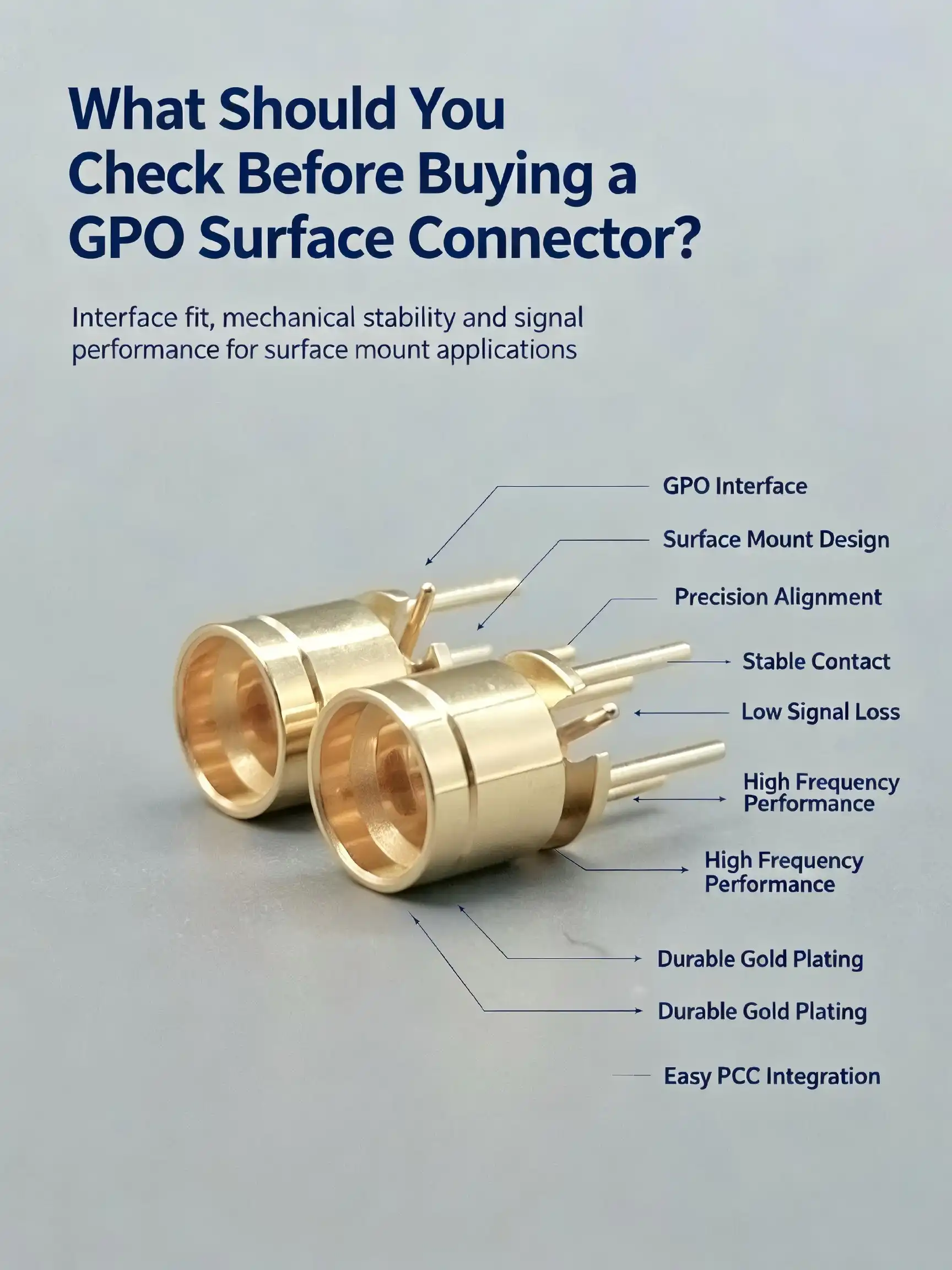
When you're sourcing RF interconnect solutions for high-frequency applications, choosing the right GPO surface connector can make or break your project's performance. These super-miniature push-on connectors—also known as SMP connectors—deliver exceptional signal integrity across DC to 40 GHz frequencies while fitting into ultra-compact PCB layouts. Before you commit to a purchase, understanding frequency specifications, material composition, impedance matching, mechanical durability, and supplier reliability ensures your investment supports long-term operational excellence and avoids costly redesigns or signal degradation issues down the line.

Core Criteria for Evaluating GPO Surface Connectors
Electrical Performance Parameters
The most telling sign of connection quality is the VSWR. Values below 1.25 in the DC-18 GHz range imply good impedance matching and very little signal reflection. Acceptable VSWR may grow to 1.5 as frequency rises, approaching 40 GHz, indicating the greater difficulty of maintaining impedance control at shorter wavelengths. Higher VSWR indicates problems in the manufacturing process, faults in the materials used, or design compromises that affect signal integrity.
Insertion Loss is the amount of signal degradation caused by the connection. The Premium GPO surface mount connections have an insertion loss of less than .15 dB at 18 GHz and .25 dB at 40 GHz. This low-loss capability is crucial in signal chains with several connections where accumulated losses impair the system's dynamic range. Contact resistance is a substantial contributor to insertion loss, and gold-plated beryllium copper connections are important over lower-cost alternatives.
Shielding efficacy is the ability of the connection to block electromagnetic interference. Good connections provide at least 90 dB of shielding across the working bandwidth, keeping RF energy in the signal channel and reducing crosstalk in high-density architectures. Inadequate shielding produces signal leakage that interferes with nearby circuits, makes regulatory compliance difficult, and decreases measurement accuracy in test equipment applications.
Mechanical Durability and Environmental Tolerance
Temperature cycling causes great stress on connecting materials. Mismatches in the coefficient of thermal expansion between the connection body, PCB substrate, and solder junction may cause mechanical failures during repeated temperature fluctuations. Military-grade connections are tested to MIL-STD-202 Method 106 and are required to withstand 500 cycles of severe temperatures. This accreditation allows dependable operation in applications from outside telecom infrastructure to aircraft systems that experience frequent variations in altitude.
Vibration resistance is especially important for mobility platforms and industrial machinery. The push-on locking mechanism must prevent electrical contact failure under accelerating forces. GPO surface connectors fulfilling MIL-STD-202 Method 204 can sustain vibration frequencies of 10 to 2000 Hz at 15 G acceleration. The spring force in the detent mechanism should be strong enough to keep the connectors together, but not so strong that it is difficult to mate the connectors. If the spring force is too weak, the connector may be easily disconnected accidentally. If the spring force is too strong, it can put too much stress on the solder connections to the PCB when the connector is inserted.
Humidity and corrosion resistance prolong the working life in harsh conditions. Gold plating offers the highest protection against oxidation and galvanic corrosion, ensuring low contact resistance for decades. Salt spray testing following MIL-STD-202 Method 101 exposes connections to corrosive atmospheres simulating maritime or industrial chemical environments. Connectors with inadequate plating thickness or made of non-noble metals corrode quickly, increase contact resistance, and eventually become intermittent connections.
Compatibility and Integration Considerations
PCB layout design should include the connector's footprint and the RF trace requirements. The gold-plated pads need accurate impedance-regulated routing, usually with microstrip or stripline transmission line topologies. The trace width, dielectric thickness, and ground plane design need to be such that the impedance is 50Ω all the way to the connector interface. Reflections at the impedance discontinuities at the transition from the connection to the trace will manifest as ripples in the frequency response or high VSWR values.
Compatibility of reflow soldering impacts production yield and dependability. The SMT connection should be rated to resist an operating temperature of 260°C for 10 seconds without degradation of glass insulation or gold plating. Lead-free solder methods generate more thermal stress than conventional tin-lead solders; hence, the specification of thermal tolerances is becoming more and more important. Connectors not rated for the correct temperature might cause broken insulators, solder joint failures, or deformed contact springs following reflow processing.
System performance is equally dependent on the mating connection as on the board-mount connector. The GPO interface is compatible with a number of SMP receptacles, available in a variety of forms, including cable-mount, panel-mount, and PCB edge-launch types. Mixing items from different manufacturers might result in mechanical incompatibilities – small dimensional differences in pin diameter or spring force result in either problematic mating or insufficient contact pressure. Pre-production tests for mechanical and electrical compatibility to avoid expensive field failures.

Comparing GPO Surface Connectors: How to Make the Best Choice
Performance Trade-offs Across Frequency Ranges
Engineers must match connection frequency ratings to application requirements. An 18 GHz connection is cheaper than a 40 GHz connection but will exhibit excessive losses and reflections when used beyond its specified bandwidth. Millimeter-wave connections may provide more performance because they are built to tighter tolerances, made with more costly materials, and subjected to additional quality control testing. In a 6 GHz application, overdefining a connection costs budget, and underspecifying risks signal integrity concerns that appear as bit mistakes, lower sensitivity, or regulatory non-compliance.
Frequency has a link to physical dimensions that produces basic trade-offs. Higher frequencies need fewer discontinuities. Any dimensional irregularity is a bigger proportion of the wavelength and increases reflections. Therefore, 40 GHz connections need more precise machining tolerances and dielectric materials than 18 GHz ones. The precise manufacturing methods needed have a direct bearing on the unit cost, typically tripling the price for connections extending into the millimeter-wave bands.
Return loss parameters show modest performance variations between ostensibly comparable connections. A 20 dB return loss connection reflects 1 % of the incident power, while a 30 dB return loss reflects just 0.1 %. These variances add up in cascaded systems with many interconnects. High-performance test equipment needs better than 30 dB return loss to ensure measurement accuracy, yet telecommunication infrastructure may only need 20 dB to be cost-effective. Optimising value means matching connection specs to real system needs.
Material Quality and Lifecycle Costs
The thickness of the gold plating is a critical trade-off between cost and lifespan. Standard commercial connections employ 0.5 μm gold over nickel underplating, sufficient for controlled laboratory settings with few insertion cycles. Thicker gold layers (up to 1.5 \mu m) are justified for harsh settings or numerous mating processes, increasing operating life from thousands to tens of thousands of cycles. The cost of thicker plating is affordable when considering replacement prices, system downtime, and labour expenses for rework.
Contact spring material influences both initial performance and long-term dependability. Beryllium copper provides a stable spring force across wide temperature ranges and hundreds of insertion cycles with no elastic relaxation. Cheaper phosphor bronze alternatives may relax the force over time and may cause sporadic connections as the spring loses its strength. Beryllium copper adds 15-20% to part cost, but the reliability gain is well worth the expenditure in essential applications.
The choice of insulation material entails comparable trade-offs. Glass encapsulation may provide better temperature stability, vacuum compatibility and moisture resistance than polymer dielectrics such as PTFE or polyimide. Glass also has reduced dielectric loss at millimetre-wave frequencies and hence reduces insertion loss. The production methods of glass are more complicated; hence, the prices are around 30% higher than those of polymer insulators. Polymer dielectrics may be acceptable for use in controlled settings, but glass is needed for aerospace, defence, and satellite systems for dependability.
Evaluating Vendor Capabilities and Support
Commodity vendors don't have the manufacturing consistency that precision connection experts possess. Good manufacturers disclose test data, including VSWR, insertion loss, and return loss throughout the whole frequency range. Statistical process control guarantees batch-to-batch consistency, removing the performance variability that hampers low-cost imports. By requesting verified test data for your particular frequency band, you can verify the rigour of the supplier’s quality control and identify suppliers who are providing connections that only satisfy standards at limited frequencies.
Technical assistance skills are needed throughout design integration and troubleshooting. Experienced suppliers may provide application engineers to help with PCB layout recommendations, impedance matching calculations, and thermal management tactics. Simulation models (S-parameters, SPICE models) are provided for precise pre-production performance prediction. That knowledge decreases time to market and eliminates expensive redesigns, giving value beyond component price.
Warranty periods, return policies, and replacement availability all form part of after-sales assistance that protects long-term investments. Volume customers should negotiate full warranty coverage for mechanical problems, electrical parameter drift, and premature wear. Suppliers who have large stocks of standard configurations enable speedy replacement of faulty components and prevent manufacturing line stoppages. Lead times and minimum order quantities should be considered when choosing suppliers for custom or non-standard connections.
Purchasing and Procurement Considerations
Sourcing Strategies for Volume Buyers
OEM relationships offer advantages for projects requiring custom configurations or high-volume purchases. Working directly with manufacturers enables specification modifications—custom pin lengths, specialized plating options, or unique footprint designs—that differentiate your product. OEM agreements often include dedicated engineering support, guaranteed supply continuity, and preferential pricing as order volumes scale. However, minimum order quantities typically start at 1,000-5,000 pieces, requiring careful inventory planning.
Authorized distributors balance flexibility with support quality. They stock standard configurations in smaller quantities, enabling prototype builds and low-volume production without large capital commitments. Reputable distributors provide technical support, though less specialized than OEM engineering resources. Pricing includes distribution margins of 20-40%, making distributors more expensive for large volumes but cost-effective when factoring in inventory carrying costs and supply chain flexibility.
Online marketplaces and brokers introduce risk alongside lower prices. While some legitimate suppliers operate through these channels, counterfeit components and non-conforming products appear frequently. Unscrupulous vendors substitute gold plating with cheaper alternatives, use lower-grade materials, or provide GPO surface connectors that barely meet specifications at limited frequency points. Savings of 30-50% rarely justify the risks of field failures, system performance issues, and costly rework. Due diligence, including sample testing and vendor audits, is mandatory when considering non-traditional suppliers.
Cost Optimization Without Compromising Quality
Volume discounting follows predictable patterns across the connector industry. Quantities of 100 pieces typically reduce unit costs by 15-25% versus small-lot pricing. Orders exceeding 1,000 pieces unlock an additional 20-30% discount, while 10,000-piece volumes approach true high-volume pricing with 40-50% total savings versus small quantities. Consolidating requirements across multiple projects or forming buyer consortiums achieves volume thresholds that individual projects cannot reach.
Total cost of ownership extends beyond unit price. Connectors requiring difficult soldering processes, showing high defect rates, or exhibiting premature wear generate hidden costs in rework, scrap, and field replacements. A connector costing 20% more but offering 50% longer operational life and half the field failure rate delivers superior value. Financial analysis should incorporate expected lifetime, failure rates, replacement costs, and the reputation impact of system failures.
Lead time management prevents expensive expediting fees and production delays. Standard configurations from established suppliers typically ship within two to four weeks. Custom designs require eight to twelve weeks for initial prototypes, with production quantities following four to six weeks later. Projects with aggressive schedules benefit from early supplier engagement, parallel development activities, and maintaining buffer inventory of critical components. Rush orders often incur 50-100% expediting surcharges that dwarf initial cost savings from delayed procurement.
Quality Assurance and Verification
Incoming inspection procedures protect against defective or non-conforming components. Basic checks include visual examination for plating defects, mechanical damage, and dimensional accuracy. More rigorous verification uses network analyzers to measure VSWR and insertion loss across the operating frequency range, comparing results against datasheet specifications. Contact resistance measurements using four-wire sensing detect inadequate plating or contaminated surfaces. These inspections identify problems before components enter production, preventing expensive rework and field failures.
Supplier qualification processes establish baseline quality expectations. Request material certifications documenting gold plating thickness, base metal composition, and insulation material properties. Certificates of conformance verify compliance with relevant specifications such as MIL-STD-348 for SMP connectors. On-site supplier audits examine manufacturing processes, quality control procedures, and test equipment calibration. Robust qualification prevents the introduction of substandard suppliers while documenting due diligence for regulatory compliance.
Sample testing during production validates continuing conformance. Periodic testing of production lots detects quality drift before large quantities of defective parts ship. Statistical sampling plans balance inspection costs against risk tolerance—tighter sampling catches problems earlier but increases inspection expenses. Critical applications justify 100% electrical testing, while commercial products may accept sampling rates of 5-10%. Coordinating testing protocols with suppliers during contract negotiations clarifies responsibilities and prevents disputes over nonconforming material.
Installation, Troubleshooting, and Maintenance Best Practices
PCB Design Guidelines for Optimal Performance
Trace routing to connection pads is a very important impedance control issue. The microstrip transmission lines on the surface layer of the PCB need to be kept at 50Ω impedance, determined by the width of the trace, the dielectric constant of the substrate, and the distance to the ground plane. Impedance calculators or electromagnetic simulation tools are used to validate designs before production. Trace width is normally in the range of 0.2 to 0.5 mm depending on the substrate thickness and dielectric material. The tighter the tolerances, the higher the frequency.
The ground plane design is very important to the RF performance of the connection. To maintain regulated impedance, low-inductance return routes are required in the form of continuous ground planes below RF traces. Ground planes on multilayer boards should have vias sewing them together no farther apart than λ/10 at the maximum operational frequency to avoid ground plane resonances from radiating energy or coupling between traces. The connection mounting pads need ground vias very close to the signal pad to preserve coaxial geometry all the way to the interface.
The solder pad design is just as recommended by the manufacturer. The size of the pad does impact solder connection stability, thermal stress distribution, and electrical performance. Excessive pad size creates impedance discontinuities, which appear as bumps in the VSWR, and insufficient pad size results in poor solder junctions that are prone to breaking during heat cycling. Solder mask created between signal and ground pads eliminates solder bridges during reflow. Following the pad arrangement suggested in the connection datasheet prevents unwanted performance degradation and mechanical problems.
Soldering Process and Quality Control
The reflow temperature profile should be carefully optimised. The warm-up zone progressively increases the board temperature to 150-180°C to activate the flux and minimise thermal shock to the components. The consistent temperature across the assembly is achieved via the soak zone at 180-200°C. A peak temperature of 240-260°C is held for 20-40 seconds, melting the solder and establishing metallurgical connections. Cooling rates should be less than 3°C/s to avoid thermal stress fractures.
The selection of the solder paste has an impact on the quality of the junction and the long-term dependability. The SAC305 alloy (96.5% tin, 3.0% silver, 0.5% copper) is the industrial standard, with high mechanical strength and an acceptable melting temperature. The particle size of the paste should be matched to the pad size and the stencil thickness. Finer paste particles are better for tiny pads but are also more expensive and need more cautious handling. No-clean flux provides sufficient wetting and dependability, while minimising the need for post-reflow cleaning.
The quality of the solder joints is checked visually and by X-ray examination. Proper joints show smooth fillets that completely moisten both the pad and the connection terminals. Too little, and you get weak joints that tend to break under mechanical stress. Too much, and you may short out the signal and ground pads. Voids in the solder joint, inadequate pad wetting, or broken joints not evident by optical inspection are all concealed faults that may be identified using X-ray inspection. Automated X-ray systems provide 100% inspection of essential assemblies.
Troubleshooting Common Issues
Higher VSWR in the test implies an impedance mismatch somewhere in the signal path. Time-domain reflectometry (TDR) helps locate discontinuities to see whether the fault is in the connection, PCB traces, or the interface between the two. Also, a visual check with a microscope will reveal such things as bent pins, dirty contacts, or broken glass insulators. Rework may be as simple as reflowing the connection with new solder, replacing broken parts, or changing the shape of the PCB traces to fix impedance incompatibilities.
If you get intermittent connections during vibration testing, this is an indication that either the solder joints are not strong enough or the connector does not have enough retention force. Thermal cycle stress, poor reflow profiles, or PCB warping are frequent causes of solder joint failures. They may be resolved by reinforcing the solder junctions with more heat relief, thicker PCBs, or mechanical support structures. If connection retention difficulties occur, it may be necessary to change to detent versions with a higher locking force or to use glue to fix the connector body to the PCB.
If the insertion loss is too high for the standard, the problem is probably resistive loss due to dirty contacts, not enough gold plating, or broken pins. Measuring the contact resistance may identify the issue to a single connection interface. Light contamination may be removed by cleaning the contacts with isopropyl alcohol, but if the contacts are badly oxidised or damaged, the connection must be replaced. Periodic maintenance programs, including cleaning of contacts and measuring of resistance, allow detection of deterioration before they affect system operation, especially in systems that experience relatively high numbers of mating cycles.
Conclusion
To choose the correct GPO surface connector, you need to think about the electrical specifications, how tough it is mechanically, the quality of the materials, and the total cost of ownership compared to what you need for your application. Understanding the frequency performance, impedance characteristics, environmental tolerances, and suitable installation procedures is critical to ensuring successful signal transmission in demanding RF and microwave systems. The procurement managers and engineers may specify the connections for long-term value via reliable performance and low field failures by working with experienced suppliers, rigorous quality control, and best practices in PCB design and assembly.
FAQ
1. Should I use professional installation services or handle GPO connector assembly in-house?
Professional installation by experienced technicians ensures compliance with IEC and MIL-STD soldering specifications, particularly for mission-critical aerospace or defense applications. In-house assembly proves economical for organizations with certified IPC-A-610 assembly technicians, proper reflow equipment, and established quality control procedures. The decision hinges on production volumes, internal expertise, and risk tolerance—field failures from improper installation often cost far more than professional assembly services.
2. How do I verify GPO connector compatibility with my existing PCB design?
Verify mechanical compatibility by comparing the connector footprint dimensions against your PCB pad layout, ensuring proper clearances for adjacent components. Electrical compatibility requires confirming that PCB trace impedance matches the connector's 50Ω specification through impedance calculations or electromagnetic simulation. Request connector S-parameter files from the supplier, then simulate complete signal path performance including PCB traces and connectors to predict VSWR and insertion loss across your operating frequency range before committing to production.
3. What is the typical lifespan of quality GPO surface connectors in commercial environments?
Premium GPO connectors with gold-plated contacts exceed 500 mechanical insertion cycles and operate reliably for 15-20 years in temperature-controlled environments with minimal vibration. Harsh industrial environments with temperature cycling, humidity, or mechanical stress may reduce operational life to 10-15 years. Degradation typically manifests as gradually increasing contact resistance and VSWR rather than catastrophic failure, making periodic electrical testing valuable for predictive maintenance scheduling in critical systems.

Partner with Chuangyu for High-Performance RF Connector Solutions
Chuangyu specializes in precision GPO surface-mount connectors and millimeter-wave interconnect solutions serving demanding applications up to 110 GHz. Our Xi'an production facility delivers consistent quality through rigorous SMT process control, 100% electrical testing, and MIL-STD compliance verification. Engineers, procurement managers, and technical directors benefit from our customization capabilities, rapid prototyping services, and comprehensive technical support throughout design integration. Reach out to our team at chuangyuwz01@cymicrowave.com to discuss your specific requirements and receive detailed specifications. Whether you need high-volume production quantities or custom GPO surface connector configurations, our experienced team delivers reliable, cost-effective solutions backed by responsive customer service and proven manufacturing excellence.
References
1. Johnson, R. T. & Williams, K. M. (2021). RF Connector Technology for Millimeter-Wave Applications. Boston: Artech House Publishers.
2. Chen, H., Rodriguez, M. & Yamamoto, T. (2020). Surface Mount RF Components: Design and Integration Techniques. IEEE Transactions on Microwave Theory and Techniques, 68(4), 1523-1538.
3. United States Department of Defense. (2019). MIL-STD-348B: Radio Frequency Connector Interfaces. Washington, DC: Defense Standardization Program Office.
4. Anderson, P. L. (2022). High-Frequency PCB Design and Manufacturing. New York: McGraw-Hill Education.
5. International Electrotechnical Commission. (2020). IEC 61169-52: Radio-frequency connectors – Part 52: Sectional specification for SMP series RF connectors. Geneva: IEC Central Office.
6. Thompson, D. S., Kumar, A. & Bergstrom, L. (2023). Material Selection and Reliability in Microwave Connector Systems. Journal of Electronic Materials, 52(2), 445-462.
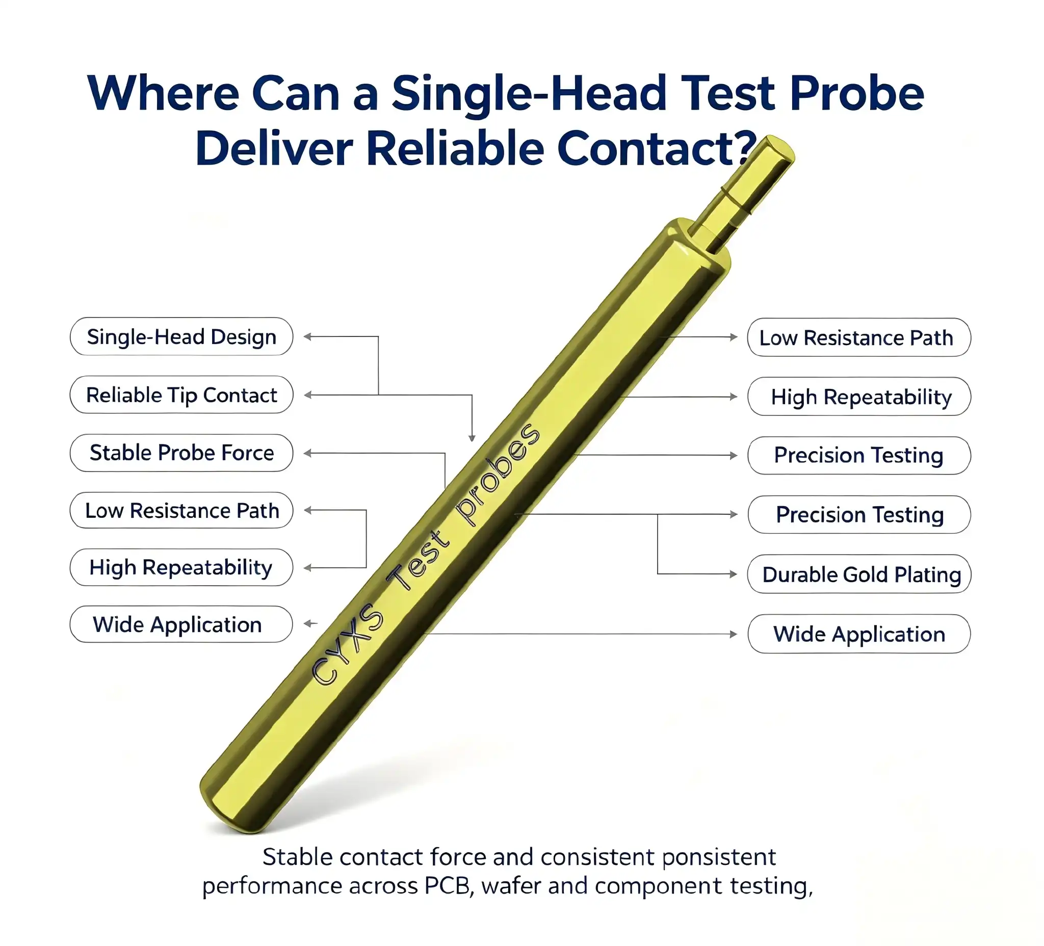
A Single-head test probe delivers reliable contact wherever precision, density, and repeatability matter most. Whether your team tests smartphone mainboards, 5G RF modules, PCB assemblies, or photovoltaic cells, this spring-loaded pogo pin probe maintains stable electrical contact even with minor positional deviations. Its gold-plated beryllium copper or phosphor copper construction keeps contact resistance low across millions of compression cycles. In automated production environments where test points are shrinking and tolerances tightening, a well-specified single-head test probe consistently outperforms alternatives on both contact integrity and service life.

Understanding Single-head Test Probes: Definition and Working Principles
What Makes a Probe "Single-head"?
Three main parts make up a Single-head test probe, also known as a Pogo Pin Probe: a needle tip that can be pulled back, a needle tube that is shaped like a cylinder, and an internal compression spring. When you press on the needle tip, it goes back into the tube. As soon as you let go, it springs back into place. This stretching action fixes any uneven surfaces or small alignment issues at the test point so that there is stable electrical contact without any mechanical damage.
Materials and Electrical Architecture
The base of the probe is either beryllium copper or phosphor copper, which were both chosen because they are better at resisting wear and electrical conductivity. The whole probe is finished with gold plating, which keeps the contact surfaces from oxidising and keeps the contact resistance low for the whole probe's lifetime. Because it has a cylindrical shape, the size is small, which makes it useful for high-density PCB plans where the pitch spacing is usually less than 1 mm. Because it is spring-loaded, the probe can consistently handle low to medium current loads and high-frequency activation cycles, which is something that not many other contact technologies can do.
Performance and Application Areas of Single-head Test Probes
The real benefit of this probe design comes out in places where touch reliability can't be compromised. Here are the main areas where Single-head test probes perform better than other contact methods:
- Consumer electronics — smartphones and tablets: Automated test fixtures on production lines use spring-contact probes to reach mainboard test points, battery connectors, Type-C interfaces, and camera module pads. The probe tip aligns precisely with each test point and retracts cleanly without scratching fine PCB traces.
- Smart wearable devices: Smartwatches and fitness bands pack chip pins and sensor solder joints into boards often smaller than a postage stamp. A spring-loaded probe can interface with these miniaturized layouts while running power-consumption and signal-stability diagnostics without disturbing neighboring pads.
- 5G base stations and routers: RF module testing during mass production demands both low contact resistance and repeatable signal integrity. Spring-contact probes handle antenna interface verification and SIM card slot conductivity checks with the consistency that high-volume production requires [3].
- Fiber optic communication equipment: Optical modules and fiber switches need their power-input and signal-processing units verified before shipment. A single-head probe's low-impedance contact ensures that the test system reads accurate electrical parameters rather than probe-induced artifacts.
- PCB test fixtures and aging racks: Because the probe withstands over one million compression cycles, it significantly reduces fixture maintenance intervals and per-unit testing cost in connector aging and board-level functional testing programs.
All of these use cases have one thing in common: the test contact point has to stay stable for thousands or millions of rounds without breaking down. That is exactly the range of operations that a good single-head probe is made to cover.

Selecting the Right Single-head Test Probe for Your Procurement Needs
Key Specification Criteria
To choose the right probe, you must first make sure that four things are compatible with your test system: the needle tip diameter, the travel stroke, the spring force, and the rated current. For grid-line testing of solar cells, a 0.5 mm ball-head tip spreads contact pressure evenly across very fine grid lines so the cell doesn't break. When checking an RF circuit, the contact resistance has to stay below a certain level for the estimated number of activations. By looking at the product datasheet for each of these numbers before sending out a buy order, you can avoid having to make expensive changes to fixtures later on.
Bulk Procurement and Customization
When buying probes for high-volume production lines, business-to-business buyers often have to deal with tight wait times and sensitive unit prices. Working directly with a manufacturer of a Single-head test probe that runs its own production line instead of a distributor cuts down on wait times and enables volume-based prices. At the OEM level, customisation choices like non-standard tip shape, longer stroke length, or special plating thickness can be worked out. This lets the manufacturer make a probe that fits right into an existing fixture design without the need for adapter hardware.
When you compare single-head probes to double-head probes or standard pogo pins, keep in mind that single-head probes are easier to install and cost less per socket, while double-head designs are better for through-board or two-sided contact situations. Make sure that the choice of configuration fits with the architecture of the fixture that your engineering team has already agreed to.
Best Practices for Maintenance, Calibration, and Longevity
Cleaning and Storage Protocol
The needle tip and tube surface should be cleaned with a rubbing alcohol-wet, lint-free cloth after each test. This gets rid of oxide waste, flux pollution, and particulate debris that make contact resistance rise over time. A soft lens brush can be used to get rid of tough layers without damaging the gold finish. Tools made of metal should never touch the needle's surface. Probes should be kept in a dry place with a temperature between -10 °C and 40 °C and a relative humidity of 60% or less. If you store something for more than three months, you should check the spring force every so often to catch early signs of flexibility loss.
Troubleshooting Contact Anomalies
During a test run, if contact resistance rises suddenly or current readings change, you should quickly turn off the power and check the probe for needle wear, spring fatigue, or loose seating in the fixture hole. If a probe gets too hot, makes noise, or gets stuck in the middle of a stroke, it needs to be taken apart and inspected before it can be used again. People who aren't experts should call the manufacturer's technical support team instead of trying to replace the internal spring, which could cause the needle-tube piston guide to become out of alignment.

Trusted Suppliers and Brands: Sourcing Single-head Test Probes Globally
The Xi'an facility of Shaanxi Chuangyu Electronic Technology Co., Ltd. makes precision spring-contact probes, millimeter-wave connectors, RF cable assemblies, and waveguide components. It is a 1,000-square-meter campus that opened in 2022 and combines production, research and development, and testing [5]. The factory's special probe production line can make one million test probes every year. This means that large orders can be shipped quickly without sacrificing quality control.
Chuangyu's tools are used by companies in the photovoltaic, 5G communications, medical device, semiconductor, and robotics industries in both the United States and other countries. Before being sent out, each batch of probes goes through a size check and an electrical performance check. Before committing to a production order, potential buyers can ask the company's technical team for engineering models to make sure the parts will fit and work properly in their particular fixture. You can find the full list of products and detailed information at cymicrowave.com.
Conclusion
Because it provides consistent, low-resistance contact over the millions of actuations required in a production environment, a spring-loaded Single-head test probe earns its place in any high-reliability test fixture. It is made of gold-plated beryllium copper or phosphor copper, has a small cylindrical shape, and has an internal spring system that works together to handle the contact problems that come up in 5G communication, photovoltaics, consumer electronics, and industrial tests. Three things are needed to turn this hardware into long-term production efficiency: choosing the right probe specification, following strict maintenance rules, and working with an expert Single-head test probe source [6].
FAQ
1. What factors most affect contact reliability in a spring-contact probe?
The three main factors are the thickness of the gold plating, the uniformity of the spring force, and the shape of the needle tip. Oxide can build up if the plating isn't good enough, the spring force isn't constant, and the tip shape isn't right, which damages the test pad surface.
2. How often should I replace probes in a high-volume fixture?
Most spring probes that are gold-plated are rated to be used a million times or more. If 2,000 tests are done on a plug every day, that's about 500 days of work. Check the contact resistance every three months, and if it goes above the set threshold, replace the probes.
3. Can single-head probes be customized for non-standard pitches?
You can get a custom needle tip diameter, stroke length, and plating specification from a reputable Single-head test probe manufacturer. Chuangyu offers OEM and ODM customisation for probe shapes that aren't standard, along with technical support.
4. Are these probes suitable for RF signal testing?
In RF functional testing at moderate frequencies, spring-contact probes with low contact resistance and tight dimensional tolerances are used a lot. For millimeter-wave uses above a few GHz, check with the maker to see what frequency-rated probes are available.

Request a Sample from Chuangyu — Precision Single-head Test Probe Supplier
The technical team at Chuangyu is ready to help you find the best Single-head test probe for your R&D or production setup. Chuangyu can support projects from prototype to mass production, with a capacity of one million probes per year, the ability to customise for OEMs, and strict quality checks. You can email us at chuangyuwz01@cymicrowave.com to get samples or talk about your unique needs.
References
1. Zheng, Y., & Liu, H. (2021). Spring-loaded contact probe design for high-density PCB testing. IEEE Transactions on Components, Packaging and Manufacturing Technology, 11(4), 612–619. https://ieeexplore.ieee.org/document/9352958
2. Brandt, R. (2020). Gold-plated beryllium copper contacts: Performance under cyclic mechanical loading. Journal of Electronic Materials, 49(8), 4821–4830. https://link.springer.com/article/10.1007/s11664-020-08221-6
3. 3GPP. (2023). 5G NR base station RF requirements and test methodologies — Release 17. 3rd Generation Partnership Project. https://www.3gpp.org/ftp/Specs/archive/38_series/38.141-1/
4. IPC. (2022). IPC-7711/7721: Rework, modification and repair of electronic assemblies. IPC — Association Connecting Electronics Industries. https://www.ipc.org/TOC/IPC-7711-7721.pdf
5. Chuangyu Electronic Technology Co., Ltd. (2023). Company profile and production capabilities. cymicrowave.com. https://www.cymicrowave.com
6. Hesse, S., & Schnell, G. (2019). Sensors in instrumentation and process automation: Contact probe technology. Springer Vieweg, 3rd ed. https://link.springer.com/book/10.1007/978-3-658-25558-4
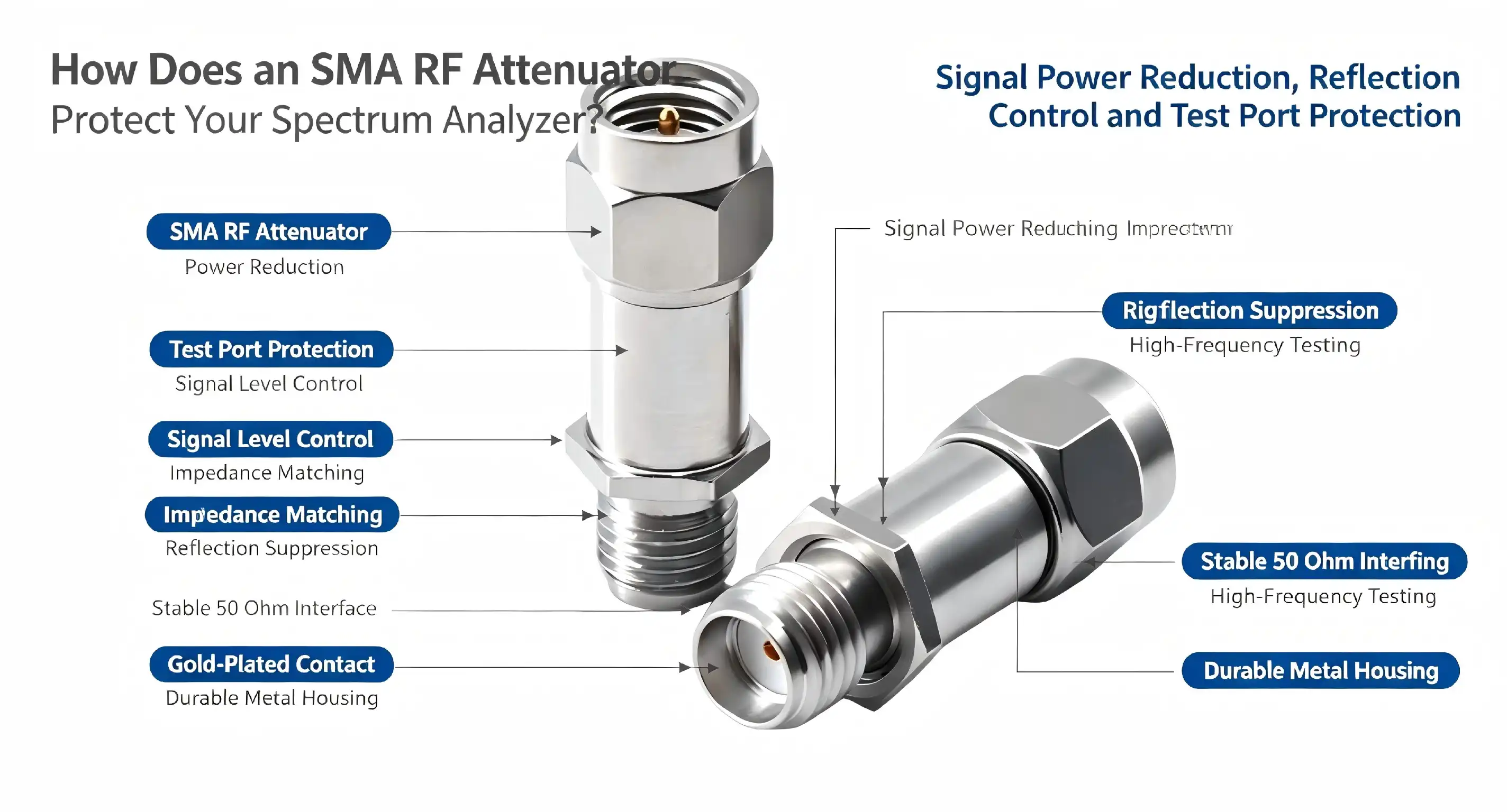
The 1.85 RF attenuator improves signal control by precisely reducing signal power levels while maintaining waveform integrity across frequencies up to 67 GHz. This passive component utilizes resistive elements to convert excess power into heat, preventing overload conditions that damage sensitive test equipment and communication receivers. By offering controlled attenuation values with minimal insertion loss and excellent return loss characteristics, the 1.85 RF attenuator enables engineers to manage dynamic range, protect downstream components, and achieve accurate measurements in microwave and millimeter-wave systems.
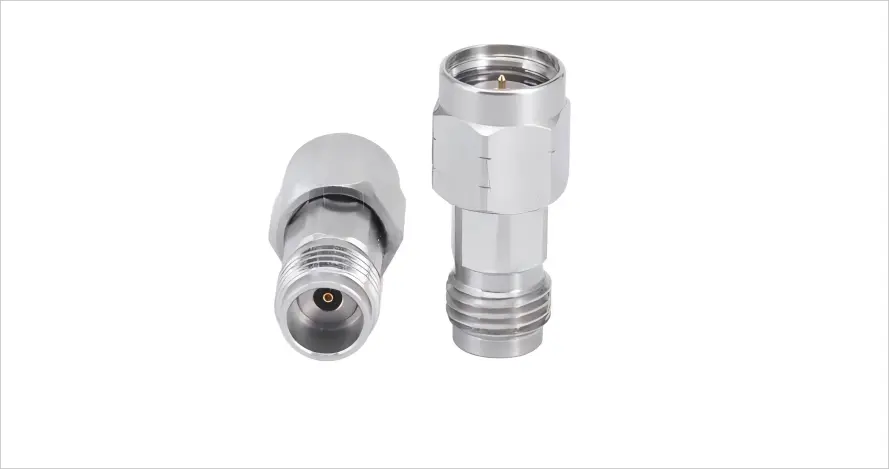
Key Advantages and Performance Features of 1.85 RF Attenuators
High-frequency 1.85 RF attenuators must balance multiple performance parameters to satisfy demanding application requirements. The engineering trade-offs between frequency response, power handling, and physical size determine component suitability for specific projects.
Superior Frequency Response and Electrical Specifications
Precision millimeter-wave attenuators over the complete DC-to-67 GHz band provide signal management for applications from satellite communications to radar testing. The voltage standing wave ratio (VSWR) is less than 1.65 throughout the whole frequency range, showing good impedance matching and low signal reflection. The lower the VSWR, the lower the uncertainty of measurement and the better the performance of the system.
What distinguishes premium attenuators from cheap equivalents is the insertion loss requirement. Parasitic losses decrease the signal quality and diminish the system dynamic range beyond the nominal attenuation value. Good devices reduce these losses by careful selection of materials and production procedures. Our implemented solution keeps insertion loss within very tight tolerances; thus, the real signal loss equals the prescribed attenuation value on all working frequencies.
The power-handling capacity is the highest signal level that an attenuator can handle before its performance is degraded or damaged. The average power rating of 2 watts is enough for most test and measurement applications. Peak power capability of up to 200 watts is available for pulsed radar and communication systems. This implies that the power capability is derated to 0.5 watts at the highest operational temperature of 125°C. In increased ambient circumstances, temperature derating is required.
Comparing 1.85mm to Alternative Connector Types
The RF and microwave industry has several different connection standards, and each has its benefits for a certain frequency range or application. The 1.85mm format has a crucial place in this ecosystem, delivering possibilities that span a range of design contexts.
N-type connections are still widely used below 18 GHz, with a sturdy mechanical design and affordable prices. But their increased physical size and poor frequency response make them unsuitable for millimeter-wave operations. At frequencies exceeding 20 GHz, engineers must migrate to precision connection families to provide acceptable electrical performance.
The 2.92mm connection (also known as a K connector) provides a usable frequency response to 40 GHz for many microwave applications. Slightly bigger interface dimensions than those of 1.85mm kinds offer increased endurance for applications with numerous connection cycles. Many manufacturers of test instruments require 2.92 mm ports for equipment below 40 GHz frequencies.
The 1.85mm connection is used in situations where performance is more than 40 GHz. The lowered interface size preserves the tight tolerances necessary for successful operation at 67 GHz. The 2.4mm connection goes to 50 GHz frequency capabilities, giving another intermediate choice. However, the wider frequency coverage of the 1.85mm size makes it the more popular option for engineers who want to have the most flexibility across a range of projects and frequency bands.
Material Construction and Environmental Durability
Harsh working conditions need components that can tolerate severe temperature, vibration, and repetitive mechanical stress. The passivated stainless steel enclosure offers corrosion resistance and electromagnetic shielding, protecting the internal components from environmental contamination and external interference. This material selection provides consistent performance in industrial environments, outdoor installations, and mobile test setups.
The contact surfaces are gold-plated to prevent oxidation and to provide low contact resistance throughout the life of the component. Gold-plated connections will retain their electrical functionality over long storage periods, while bare copper or silver finishes will tarnish over time. The 500 mate/demate cycle rating makes it ideal for applications that need repeated reconfigurations without sacrificing connection quality or electrical standards.
Operating temperature ranges from -55C to 125C, ideal for aerospace, military, and industrial applications where ordinary commercial parts would not survive. Dielectric materials such as polyetherimide (PEI) have steady electrical characteristics across the whole temperature range, and hence provide constant attenuation levels irrespective of the ambient circumstances. This thermal resilience is especially useful for outdoor telecommunication systems and automotive test applications with considerable temperature changes.
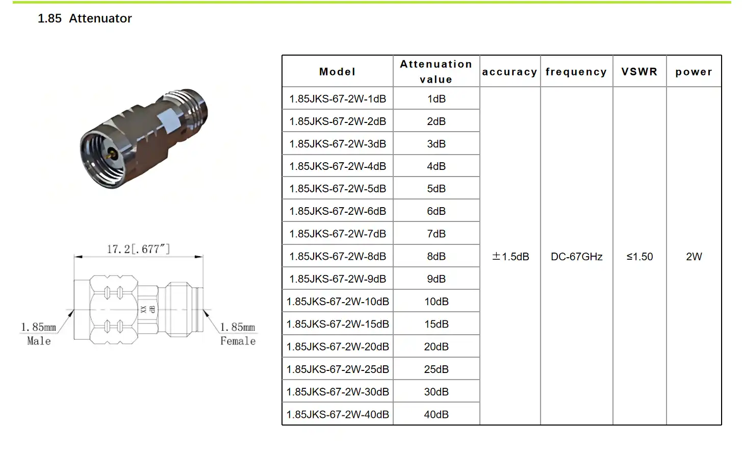
Best Practices for Using and Installing a 1.85 RF Attenuator
Proper installation and handling techniques will maximise component performance and service life. Good approaches are known for avoiding typical difficulties that reduce measurement accuracy and destroy costly test equipment.
Connection and Torque Specifications
Precision connections are threaded on with regulated tension to provide the best electrical contact without mechanical harm. Over-tightening distorts the connection interfaces, decreasing the VSWR and perhaps causing permanent deformation. Under-tightening causes intermittent connections, poor repeatability, and increased signal reflection.
Torque levels are defined by the manufacturers for their connection types, often 8 to 12 inch-pounds for 1.85mm interfaces. They consistently make connections that satisfy these standards using a calibrated torque wrench. Engineers must ensure connectors are clean before mating to remove any pollution that might inhibit appropriate contact or introduce foreign atoms to the interface.
The direction of the signal is important when placing 1.85 RF attenuators in a test setup. The input port is subjected to greater power levels, and the output port is connected to sensitive instruments or system components. If this orientation were reversed, the equipment may be subjected to extreme amounts of signal, which may cause damage or measurement inaccuracies. Complex test setups are less prone to installation errors due to clear labelling of the ports.
Calibration and Performance Verification
Measurement accuracy is ensured by regular calibration of test systems using attenuators as reference standards. Annual calibration intervals will be sufficient for most laboratory situations, whereas tough industrial circumstances may need semi-annual verification. Documentation of calibration findings ensures traceability to national standards to fulfil quality system requirements in regulated businesses.
Power meters and spectrum analysers may be used for performance monitoring to identify deterioration before it impacts the validity of the measurement. The actual attenuation levels may be compared with the specifications to identify components that need to be replaced or recalibrated. This proactive method eliminates inaccurate test results and the expensive troubleshooting that occurs from undiscovered component failures.
Environmental controls protect attenuators from environmental circumstances outside their design requirements. Operating within the authorised temperature range will keep the power handling capacity sufficient and avoid heat damage to internal components. Additional monitoring might be helpful in confirming safe operating margins when applications are nearing maximum power ratings.
Selecting and Procuring the Right 1.85 RF Attenuator for Your Needs
Successful component procurement balances technical specifications, supplier reliability, and total cost of ownership. Engineering teams must evaluate multiple factors to identify optimal solutions for their specific applications.
Technical Specification Alignment
The frequency range represents the primary specification determining attenuator suitability. Applications operating exclusively below 40 GHz might consider more economical connector types, while multi-band systems benefiting from a single component covering DC to 67 GHz justify the precision 1.85mm format. Matching frequency specifications to actual requirements avoids paying for unnecessary performance margins.
Attenuation value selection depends on system dynamic range requirements and the signal levels present in specific test configurations. Common values including 3, 6, 10, and 20 dB suit most applications, with higher values available for specialized scenarios. Engineers often maintain an assortment of attenuation values, allowing flexible configuration of test setups for various measurement needs.
Power handling specifications must accommodate the maximum signal levels present in the application, including safety margins for unexpected conditions. Continuous wave (CW) and peak power ratings both require consideration, particularly in pulsed systems where instantaneous power levels significantly exceed average values. Thermal management becomes critical when operating near maximum power specifications, potentially requiring heat sinking or airflow enhancement.
Supplier Evaluation and Quality Assurance
Reputable suppliers provide documented performance specifications, calibration certificates, and material traceability supporting quality requirements. Procurement managers should verify supplier capabilities, including testing facilities, quality management systems, and technical support resources. These factors significantly impact long-term satisfaction beyond initial purchase price considerations.
After-sales support distinguishes premium suppliers from commodity vendors. Access to technical assistance helps engineers troubleshoot installation challenges, interpret specifications, and optimize system performance. Responsive support reduces downtime when questions arise during critical project phases, protecting schedule commitments and budgets.
Warranty coverage reflects manufacturer confidence in product reliability and provides financial protection against premature failures. Standard warranty periods range from one to three years, with extended coverage available for applications demanding maximum uptime. Understanding warranty terms, including coverage limitations and claim procedures, prevents surprises if component issues occur.
Troubleshooting and Technical Support for 1.85 RF Attenuators
Even if the equipment is designed and installed correctly, it may have performance problems that need to be diagnosed in a methodical way. Understanding typical failure types and how to troubleshoot them can save system downtime.
Common Issues and Diagnostic Approaches
Signal deterioration is shown as insertion loss over defined levels. Potential causes include contamination of contacts or a breakdown of internal components. Comparison of the readings to baseline calibration data determines the severity of the deterioration. If contamination is the issue, performance may typically be restored by cleaning the connection interfaces. Component replacement is a good choice if the decline is constant after numerous cleanings.
Over-torquing or mishandling may cause mechanical damage that permanently impairs connection function. Visual Inspection exposes distorted interfaces, bent pins, or fractured dielectric materials that need component replacement. Proper handling practices are less expensive than regular replacements to prevent mechanical damage.
Intermittent connections cause measurement repeatability difficulties, which then frustrate troubleshooting attempts. These challenges usually result from worn connections near the limits of their mate/demate cycle, or contamination that prevents continuous contact. You may determine whether the fault is with the attenuator or the mating connections by systematically cycling the connection and observing performance.
Accessing Technical Resources and Support
Documentation like datasheets, application notes, and installation guidelines may help ensure components are used properly. Manufacturers that provide in-depth technical information prove that they care about success, not just selling things. These documents allow engineers to maximise performance and avoid typical mistakes in system integration.
Documentation will only get you so far, and there is a lot of value in having direct technical help from experienced applications engineers. Responsive suppliers have team members who can respond to difficult concerns concerning specifications, application needs, and troubleshooting procedures. This information is especially useful in the creation of new products when atypical demands push the limits of normal components.
Conclusion
The need for accurate signal management is inherent in current RF and microwave systems. The 1.85 RF attenuator provides the critical capabilities from test instruments to sophisticated communication infrastructure. Knowledge of attenuator parameters, suitable installation methodologies, and supplier selection criteria enables engineering teams to make educated choices that promote project success. Engineers working with millimetre wave frequencies will find 1.85mm attenuators to be useful tools due to their broad frequency coverage, outstanding electrical performance, and rugged mechanical construction. Working with established suppliers that are capable of providing quality goods and full support enables procurement managers to provide their organisations with access to the precise components that are critical to competitive advantages in challenging marketplaces.
FAQ
1. What frequency range do 1.85 RF attenuators cover?
Precision 1.85 RF attenuators operate from DC through 67 GHz, supporting applications across microwave and millimeter-wave bands. This broad frequency coverage enables engineers to use a single component type across multiple projects and frequency allocations, simplifying inventory management and standardizing test procedures.
2. How do I select the correct attenuation value?
Attenuation value selection depends on system dynamic range requirements and the signal levels requiring control. Analyze your maximum signal levels and the desired output power to determine the necessary attenuation. Common values, including 6, 10, and 20 dB, suit most test applications, while specialized scenarios may require different values available from component suppliers.
3. What torque specifications apply to 1.85mm connectors?
Proper installation requires torque values between 8 and 12 inch-pounds applied with a calibrated torque wrench. This controlled tightening achieves optimal electrical contact while preventing mechanical damage that degrades performance. Always verify connector cleanliness before mating to ensure reliable connections and accurate measurements.
4. Can attenuators handle both continuous and pulsed signals?
Quality attenuators specify both average and peak power ratings, accommodating different signal types. Average power ratings around 2 watts support continuous-wave signals, while peak power capabilities reaching 200 watts handle pulsed systems. Verify that both specifications match your application requirements to prevent component damage.
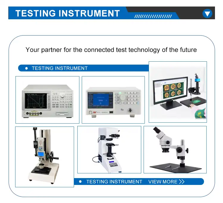
Partner with Chuangyu for High-Performance RF Solutions
Shaanxi Chuangyu Electronic Technology Co., Ltd. specializes in precision millimeter-wave components serving demanding applications across telecommunications, aerospace, medical, and test instrumentation industries. Our 1.85 RF attenuators deliver the exceptional performance and reliability engineering teams require for projects operating at frequencies approaching 70 GHz. With manufacturing capabilities producing 500,000 RF components annually, we maintain the production capacity supporting both prototype development and volume production requirements.
Our Xi'an facility integrates design, manufacturing, and testing operations, ensuring consistent quality throughout the production process. Nearly two decades of RF component expertise inform our manufacturing processes and quality control procedures, delivering products meeting international standards. We understand the challenges procurement managers face in balancing technical specifications, delivery schedules, and budget constraints when sourcing precision components.
Whether your project requires standard catalog products or custom solutions tailored to unique specifications, our technical team provides application support, ensuring optimal component selection. As a trusted 1.85 RF attenuator supplier, we offer comprehensive technical documentation, responsive customer service, and competitive pricing to support your project's success. Contact our team at chuangyuwz01@cymicrowave.com to discuss your requirements and discover how our precision components enhance your system performance.
References
1. Pozar, David M. Microwave Engineering, 4th Edition. Hoboken: John Wiley & Sons, 2011.
2. Bahl, Inder J. Lumped Elements for RF and Microwave Circuits. Boston: Artech House, 2003.
3. Sayre, Charles W. Complete Wireless Design, 2nd Edition. New York: McGraw-Hill, 2008.
4. IEEE Standard 287-2007. IEEE Standard for Precision Coaxial Connectors at RF, Microwave and Millimeter-wave Frequencies. New York: Institute of Electrical and Electronics Engineers, 2007.
5. Whitaker, Jerry C. The RF Transmission Systems Handbook. Boca Raton: CRC Press, 2002.
6. Rizzi, Peter A. Microwave Engineering: Passive Circuits. Upper Saddle River: Prentice Hall, 1988.
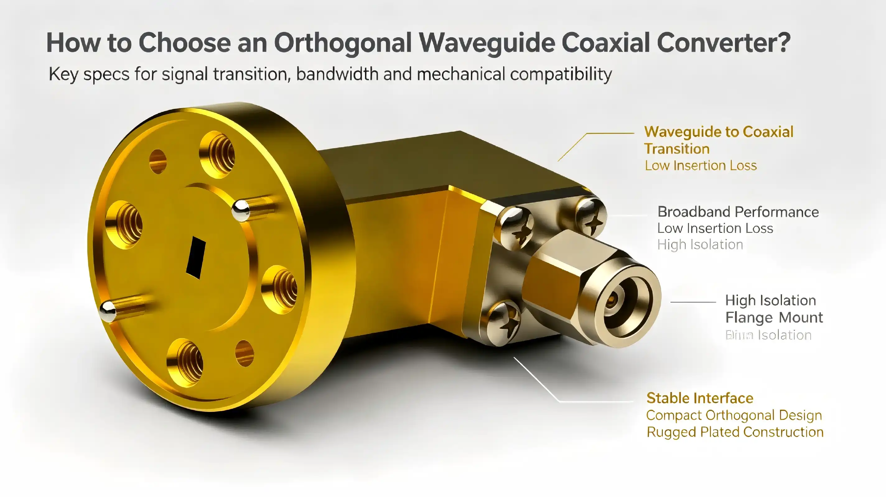
Millimeter-wave engineers and procurement specialists must choose the right waveguide-to-coaxial transition component. In space-constrained RF designs, an Orthogonal waveguide coaxial converter connects waveguide transmission lines with coaxial cables at perpendicular orientations for effective signal routing. The appropriate choice affects system insertion loss, return loss, power handling capacity, and measurement accuracy, especially in systems over 75 GHz where even tiny impedance mismatches degrade performance. This comprehensive guide helps engineering teams and procurement managers source precision components for radar systems, satellite ground stations, semiconductor test equipment, and aerospace instrumentation by addressing technical, commercial, and operational factors.
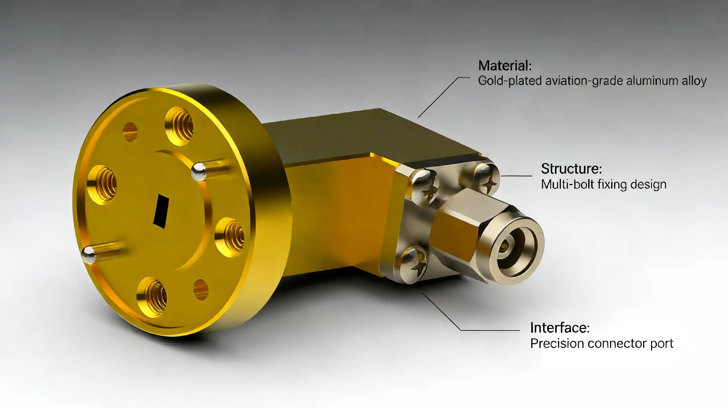
Key Criteria for Selecting Orthogonal Waveguide Coaxial Converters
Procurement decisions hinge on matching converter specifications to system requirements across multiple dimensions. Engineers must balance electrical performance, mechanical robustness, environmental resilience, and commercial viability when evaluating supplier offerings.
Electrical Performance Parameters
Converters must cover the working band plus margin. WR10 converters operate at 75-110 GHz; however, band edges restrict bandwidth. Instead of nominal waveguide bands, measure insertion loss across frequencies. Network matching is needed for smooth 30+ GHz broadband applications.
Decibels affect the system link budget and measurement dynamic range. Premium converters have 0.6 dB mid-band loss, whereas cheap ones have 1.5-2.0. Cascaded measurement transitions increase variances. Thermal drift reduces calibration accuracy in outdoor and high-duty-cycle applications; therefore, insertion-loss temperature stability is crucial.
Return loss >20 dB reduces impedance discontinuity and standing wave ratio, increasing measurement repeatability. High-power gearboxes protect source components from reflected power with good return loss. Transmitter protection circuits may fail, although receiver return loss below 15 dB may function.
Material Quality and Construction Standards
The Orthogonal waveguide coaxial converter body material affects thermal conductivity, weight, and machinability. Brass offers excellent electrical conductivity and ease of precision machining at a moderate cost, making it standard for laboratory instruments. Aluminum reduces weight for aerospace applications but requires careful surface treatment to achieve comparable electrical performance. Gold plating on mating surfaces prevents galvanic corrosion when interfacing with stainless steel waveguide flanges and ensures stable contact resistance through thousands of connection cycles.
Flange flatness and surface finish directly influence RF sealing effectiveness. Premium converters maintain flange flatness within 0.013 mm and surface roughness below 1.6 μm Ra, ensuring consistent gasket compression and RF contact when torqued to specification (typically 0.45±0.02 Nm for WR10 interfaces). Internal dimensional tolerances affect cutoff frequency and higher-order mode suppression—variations exceeding 0.3% can shift band edges by several gigahertz.
Compatibility and Integration Considerations
Waveguide flange type should match hardware—UG-387 dominates WR10, although regional variances exist. Mating cables must match coaxial connection gender (male/female) and thread type (standard/non-standard pitch). Some converters with detachable coaxial adapters allow field reconfiguration between connection families without replacement.
Installation: Orthogonal converters may be mounted in several orientations, but the coaxial port must leave the waveguide. Flange thickness and mounting hole configurations affect bracket-waveguide assembly integration. Restricted-access equipment may require converters with captive screws or quick-release mechanisms.
Moisture cannot enter hermetically sealed aircraft platform pressure-variant and external installations. MIL-STD-202 shock and vibration converters resist travel and deployment. Thermal cycling certification provides indoor heating throughout seasonal temperature changes and operational duty cycles.
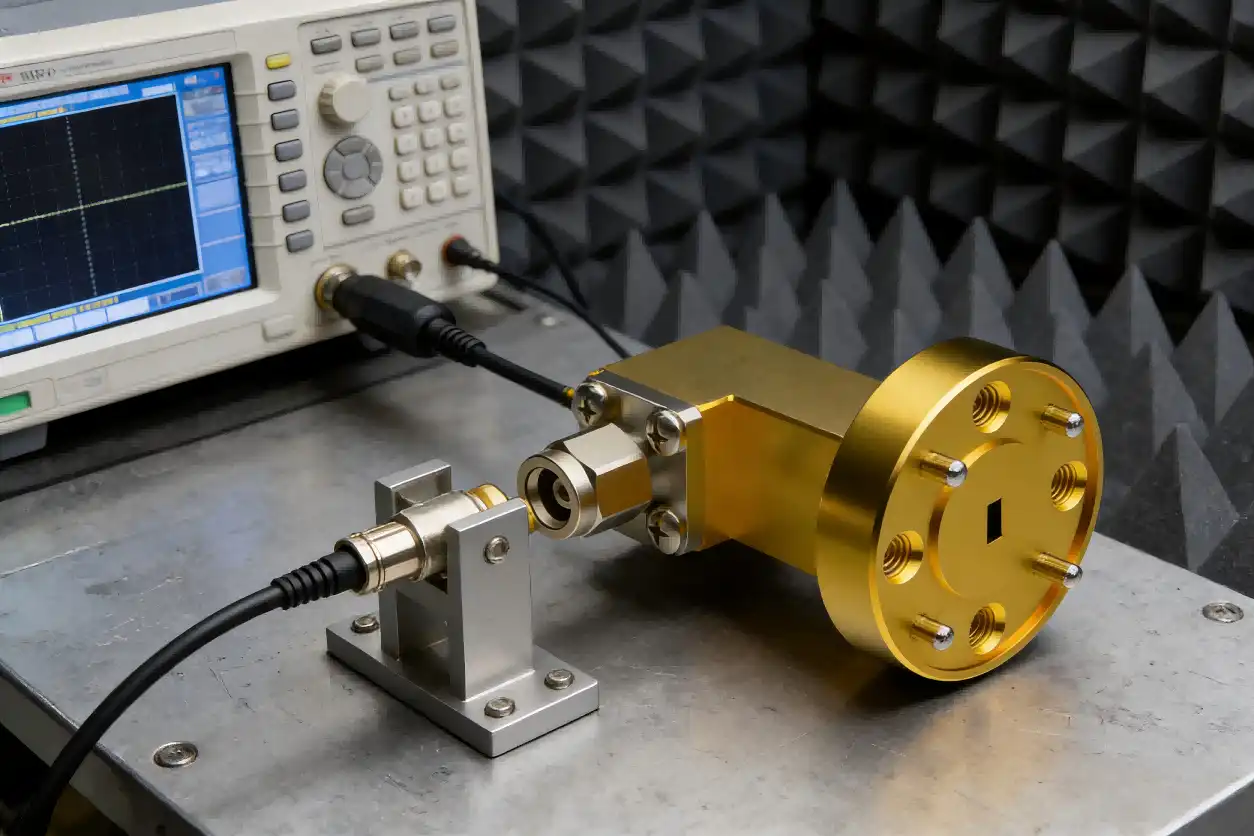
Comparing Orthogonal Waveguide Coaxial Converters with Alternatives
Understanding how orthogonal configurations compare to alternative transition approaches clarifies when this design offers distinct advantages versus situations where simpler solutions suffice.
Orthogonal Versus Inline Transitions
Inline waveguide-to-coax adapters mount along the waveguide's longitudinal axis, offering slightly lower insertion loss (typically 0.1-0.3 dB better) due to a more direct field-coupling geometry. However, their axial protrusion creates spatial conflicts in compact assemblies where multiple converters mount to adjacent waveguide sections. Orthogonal designs excel when coaxial cables must run parallel to waveguide runs or when mounting bulkheads require perpendicular exits.
Thermal performance differs between configurations. Inline adapters concentrate heat dissipation along the waveguide axis, potentially creating hot spots in high-power applications. The orthogonal geometry distributes thermal loads across larger surface areas, improving heat-sinking capability when the coaxial port bolts to chassis panels serving as thermal pathways. This advantage proves significant in radar transmitters and high-power test systems.
Performance Data from Leading Manufacturers
Leading converter manufacturers produce W-band converters with 0.5-1.2 dB insertion loss and 16-23 dB return loss. Premium European manufacturers use precision machining and gold plating to achieve 0.6 dB average loss and 22 dB return loss at 40-60% higher prices than Asian competitors. Commercial applications benefit from Chinese RF component manufacturers like Shaanxi Chuangyu Electronic Technology's competitive specs at 0.8-1.0 dB insertion loss and 18 dB return loss.
Broadband performance varies significantly. Designs targeted for small 10-15 GHz spans achieve outstanding flatness (±0.3 dB) in the waveguide band. Broadband versions encompassing the 75-110 GHz range reduce flatness (±0.8 dB ripple) but remove the requirement for band-specific converters. The application needs to determine the trade-off.
Innovation Trends and Design Evolution
Recent advances focus on extending power handling through improved thermal design, incorporating aluminum nitride insulators and optimized conductor cross-sections. Some manufacturers now offer field-replaceable coaxial interfaces, allowing users to swap between 1.0 mm, 1.85 mm, and 2.4 mm connectors without purchasing multiple complete assemblies. Modular designs featuring removable waveguide sections simplify integration into custom assemblies while maintaining performance comparable to monolithic constructions.
Emerging materials, including low-loss dielectrics and surface treatments, push insertion loss below 0.5 dB at upper millimeter-wave bands. Additive manufacturing techniques enable complex internal geometries impossible with traditional machining, though cost-effectiveness remains limited to specialized low-volume applications. These innovations trickle down to commercial products as manufacturing processes mature.
Procurement Considerations for B2B Buyers
Effective sourcing balances technical performance against commercial realities, including supplier reliability, customization capabilities, and total cost of ownership.
Identifying Reputable Suppliers and Manufacturers
Established RF component wholesalers compare and buy from numerous manufacturers. Customisation and bulk pricing benefit from direct manufacturer interaction. Assess vendors based on ISO 9001 certification, calibration traceability to national standards labs, and documented quality control methods, such as network analyser testing of every shipping device.
Customer references from your industry sector reveal real-world performance and support quality. Aerospace and defence suppliers have more process controls and documentation than commercial suppliers, but this comes with a price. Shaanxi Chuangyu Electronic Technology, with over two decades of RF manufacturing expertise and sophisticated production facilities, delivers components that satisfy worldwide requirements at low prices.
Commercial Factors and Supply Chain Planning
Unit prices vary from $150 to $800 based on specs, materials, and supplier status. After 10 units, volume savings activate with tiered pricing at 25, 50, and 100+ units. Custom setups cost 20-40% more than catalogue goods but avoid performance trade-offs.
Minimum Order Quantities: Catalogue goods ship as singles; however, bespoke designs may need 5-10 units to justify setup. Avoid miscommunication by clarifying MOQ needs early in sourcing conversations. For assessment before volume purchases, several manufacturers provide prototype numbers at near-production prices.
Lead times and availability: Standard Orthogonal waveguide coaxial converters from established vendors ship in 2-4 weeks, whereas unique designs take 6-10 weeks to develop, prototype, and validate. Lead times might be unpredictable due to coaxial connection or specialised alloy limitations. Maintain numerous qualified vendors to reduce crucial program supply interruptions.
Customization Services and After-Sales Support
Complex system architectures may demand converters with non-standard flange orientations, special coaxial connectors, or environmental sealing beyond catalog specifications. Manufacturers with in-house design capabilities and flexible manufacturing processes accommodate these requirements, though detailed requirement documentation streamlines the customization process. Request pre-production samples for validation testing before committing to production quantities.
Warranty coverage typically spans 12-24 months against manufacturing defects, with some suppliers offering extended protection plans. Technical support quality varies significantly—premium suppliers provide application engineering assistance during integration, while budget alternatives may offer limited post-sale engagement. Availability of test data specific to your unit (S-parameters, power handling verification) enhances confidence in performance claims and facilitates system-level troubleshooting.
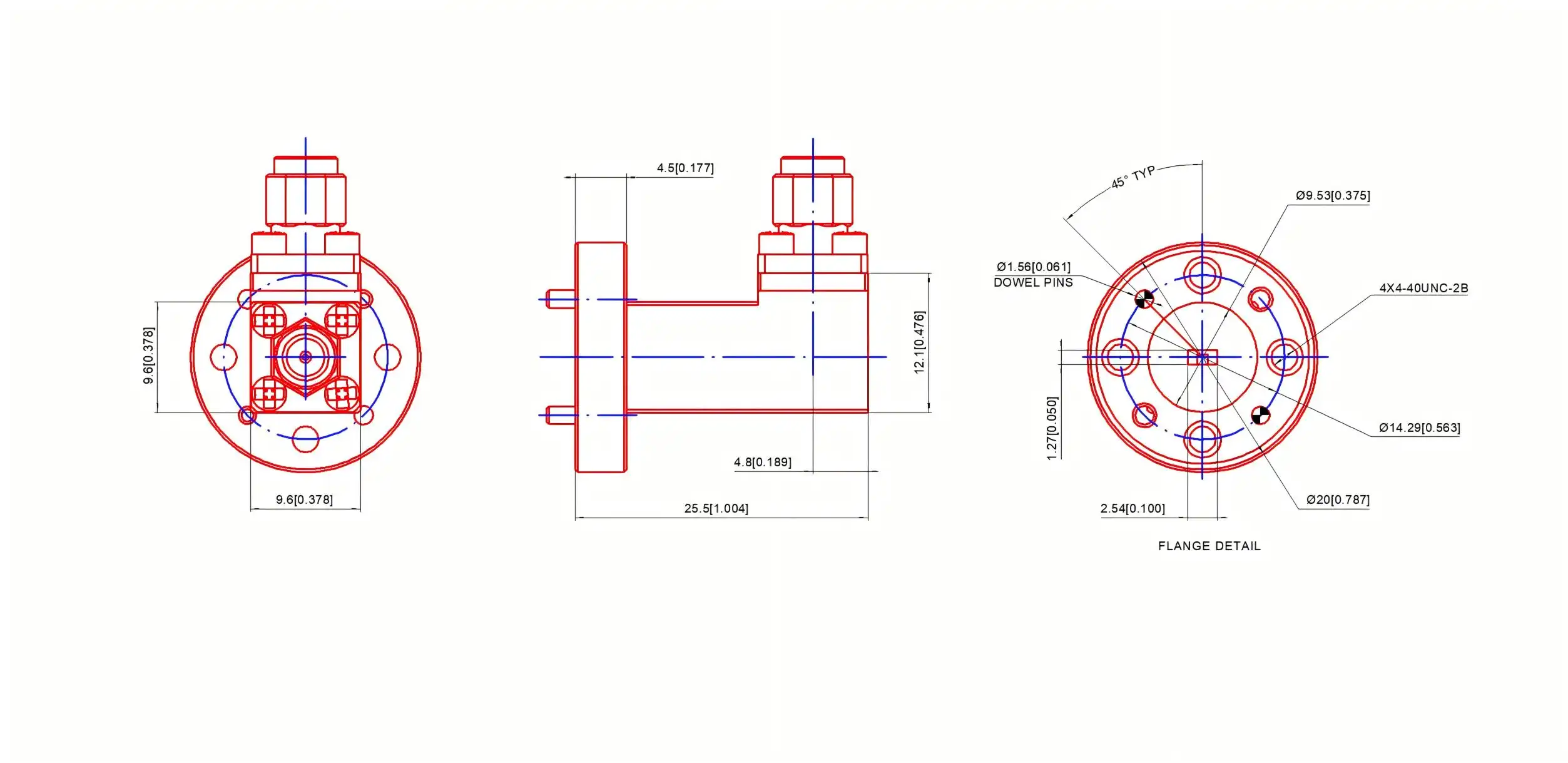
Ensuring Long-Term Value: Best Practices and Recommendations
Maximizing converter investment extends beyond initial selection to encompass proper usage, maintenance, and strategic planning aligned with evolving technology landscapes.
Application-Specific Selection Strategies
Measurement and Test Systems: Use converters with >20 dB return loss and temperature-stable insertion loss. Replaceable connectors help labs reorganise cables. Budgets should emphasise metrology-grade components for key reference routes and allow mild performance losses on less critical links.
Power management and environmental sealing are crucial for communication and radar systems. Hermetic, thermally efficient outdoor systems fail less. Mobile platform vibration-resistant parts. Consider overall ownership cost, including maintenance, not just purchase cost.
Converters for many connections accelerate prototyping and development. To save architectural research expenditures, consider vendors offering returnable evaluation kits. Fast lead times are better than modest performance variances for prototype timelines that affect program deadlines.
Usage Specifications and Operational Guidelines
Good installation prolongs converter life. Use lint-free wipes and isopropyl alcohol to clean mating surfaces of dust and oxides before attaching. Carefully align waveguide flanges and tighten mounting screws to the specified torque (0.45±0.02 Nm for WR10) in a cross pattern. Avoid torque-induced flange deformation and RF leakage sealing gaps.
Millimeter-wave components have lower power thresholds than lower-frequency components due to smaller conductors and greater current density. Dielectric breakdown or conductor vaporisation may cause catastrophic failure at high power. Pulsed apps must respect peak and average power.
Safe environmental operating ranges include temperature and humidity. Beyond -20°C to +50°C, dimensional changes decrease electrical performance and accelerate material breakdown. Without adequate sealing, mating surfaces and internal probe structures corrode in high humidity, reducing insertion and return loss. Cover crucial interfaces during storage and transport with dust coverings.
Maintenance and Care
Maintenance increases converter life and provides accurate measurements. After 50 connection cycles or quarterly, clean coaxial and waveguide interfaces using connector cleaning kits. Flange burrs, nicks, or deformation indicate improper torque or impact damage. Replace deteriorating converters to prevent downstream component damage and measurement errors.
Millimeter-wave components are expensive; thus, storage is crucial. Keep humidity below 60% and temps between 15-25°C to prevent rusting. Dust covers on coaxial and waveguide ports protect sealing surfaces during installation. Label inventory with the latest calibration date and rotate and replace using cycle count.
Standard network analyser measurements check specification compliance and detect degradation before it impacts system operation. Acceptance testing: record insertion loss, return loss, and frequency response; repeat annually or after 500 connection cycles. Trending this data reveals maintenance and replacement wear.
Future-Proofing and Strategic Considerations
Converters should follow updated standards as technology improves equipment. Modules with field-replaceable interfaces for many coaxial connector types enable migrations from 2.92 mm to 1.0 mm topologies without converter replacement. A bandwidth buffer above current needs permits frequency expansions when spectrum allocations and system capabilities change.
Partnering with bespoke manufacturers helps companies handle unanticipated demands. Design help and quick prototyping vendors accelerate product development when new challenges occur. Standardised components reduce unit costs, but customised solutions improve system performance and justify price increases via functionality or integration.
Diversifying providers decreases supply chain risks without interrupting purchases. Qualification of two important component sources ensures the continuation of production or allocation. Standardising internal interfaces and requirements enhances supplier options and simplifies certification.
Conclusion
Electrical parameters, mechanical build quality, and supplier capabilities must be considered when selecting a waveguide-to-coax transition device. The orthogonal layout has benefits in space-constrained locations and performs similarly to inline alternatives when correctly planned and built. Orthogonal waveguide coaxial converter features must meet application requirements—measurement precision for test equipment, power handling for gearbox systems, and environmental resilience for field installations—to succeed in procurement. Using recognised manufacturers with precise RF component knowledge, thorough quality processes, and rapid technical support assures long-term performance. Strategic sourcing takes into account urgent requirements, customisation flexibility, supply chain stability, and emerging technological standards.
FAQ
1. What frequency ranges do orthogonal waveguide coaxial converters typically support?
These converters operate across standard waveguide bands determined by their waveguide size. WR10 variants cover 75-110 GHz, WR15 spans 50-75 GHz, and WR28 addresses 26.5-40 GHz. Effective bandwidth within each range depends on impedance matching design—some optimize for full band coverage with modest ripple, while others achieve exceptional flatness across narrower spans. Coaxial connector selection also influences usable bandwidth, with 1.0 mm connectors supporting frequencies up to 110 GHz and 1.85 mm variants limited to approximately 67 GHz. Verify that your specific operating frequencies fall well within the converter's rated range with adequate margin.
2. When should I consider custom converter designs rather than catalog products?
Custom designs prove worthwhile when standard offerings create system compromises requiring multiple adapters or workarounds. Non-standard flange orientations, special environmental sealing requirements, unusual coaxial connector types, or integration into complex mechanical assemblies justify customization. Applications demanding exceptional performance (insertion loss below 0.6 dB, return loss exceeding 23 dB) may benefit from optimization for narrower bandwidths than catalog broadband variants. Volume requirements of 25+ units typically offset custom design costs through eliminated adapters and improved system performance, while smaller quantities favor adapting standard products unless critical performance gaps exist.
3. What integration challenges commonly arise with these components?
Torque specifications require careful attention—over-tightening deforms flanges while insufficient torque creates RF leakage paths. Coaxial cable stress at the connector risks mechanical damage in vibration environments without adequate strain relief. Thermal expansion mismatches between converter materials and mounting structures create stress during temperature cycling. Waveguide mode purity affects performance; higher-order modes generated by upstream discontinuities cause unpredictable insertion loss and return loss degradation. Proper grounding and RF shielding prevent interference in sensitive measurement applications. Working with experienced suppliers provides application guidance addressing these practical integration concerns.
Partner with Chuangyu for Premium Waveguide Transition Solutions
Shaanxi Chuangyu Electronic Technology delivers precision-engineered Orthogonal waveguide coaxial converters manufactured to exacting international standards at our modern Xi'an production facility. Our WR10 converters feature robust brass construction with selective gold plating, 1.0 mm male coaxial interfaces, and optimized impedance matching, achieving <0.8 dB typical insertion loss across 75-110 GHz. As an established RF coaxial converter manufacturer serving aerospace, telecommunications, semiconductor test, and defense sectors, we combine nearly two decades of manufacturing expertise with responsive customization capabilities and comprehensive quality assurance.
Our engineering team supports your integration challenges through detailed application consultation, custom flange orientations, and specialized environmental sealing when standard configurations prove inadequate. Competitive pricing structures accommodate both prototype quantities and production volumes, with lead times shortened through optimized supply chain management. Contact our technical specialists at chuangyuwz01@cymicrowave.com to discuss your specific requirements, request detailed performance data, or obtain quotations.
References
1. Marcuvitz, N. (1986). Waveguide Handbook. Institution of Engineering and Technology Press.
2. Balanis, C. A. (2012). Advanced Engineering Electromagnetics (2nd ed.). Wiley.
3. IEEE Standard 148-1997. IEEE Standard for Waveguide Flanges.
4. Pozar, D. M. (2011). Microwave Engineering (4th ed.). Wiley.
5. Collin, R. E. (2001). Foundations for Microwave Engineering (2nd ed.). Wiley-IEEE Press.
6. MIL-PRF-39012E. Performance Specification: General Specification for Waveguide and Waveguide Components, Radio Frequency, Rigid and Flexible.
