- English
- French
- German
- Portuguese
- Spanish
- Russian
- Japanese
- Korean
- Arabic
- Greek
- German
- Turkish
- Italian
- Danish
- Romanian
- Indonesian
- Czech
- Afrikaans
- Swedish
- Polish
- Basque
- Catalan
- Esperanto
- Hindi
- Lao
- Albanian
- Amharic
- Armenian
- Azerbaijani
- Belarusian
- Bengali
- Bosnian
- Bulgarian
- Cebuano
- Chichewa
- Corsican
- Croatian
- Dutch
- Estonian
- Filipino
- Finnish
- Frisian
- Galician
- Georgian
- Gujarati
- Haitian
- Hausa
- Hawaiian
- Hebrew
- Hmong
- Hungarian
- Icelandic
- Igbo
- Javanese
- Kannada
- Kazakh
- Khmer
- Kurdish
- Kyrgyz
- Latin
- Latvian
- Lithuanian
- Luxembou..
- Macedonian
- Malagasy
- Malay
- Malayalam
- Maltese
- Maori
- Marathi
- Mongolian
- Burmese
- Nepali
- Norwegian
- Pashto
- Persian
- Punjabi
- Serbian
- Sesotho
- Sinhala
- Slovak
- Slovenian
- Somali
- Samoan
- Scots Gaelic
- Shona
- Sindhi
- Sundanese
- Swahili
- Tajik
- Tamil
- Telugu
- Thai
- Ukrainian
- Urdu
- Uzbek
- Vietnamese
- Welsh
- Xhosa
- Yiddish
- Yoruba
- Zulu
The 1.85 RF attenuator improves signal control by precisely reducing signal power levels while maintaining waveform integrity across frequencies up to 67 GHz. This passive component utilizes resistive elements to convert excess power into heat, preventing overload conditions that damage sensitive test equipment and communication receivers. By offering controlled attenuation values with minimal insertion loss and excellent return loss characteristics, the 1.85 RF attenuator enables engineers to manage dynamic range, protect downstream components, and achieve accurate measurements in microwave and millimeter-wave systems.
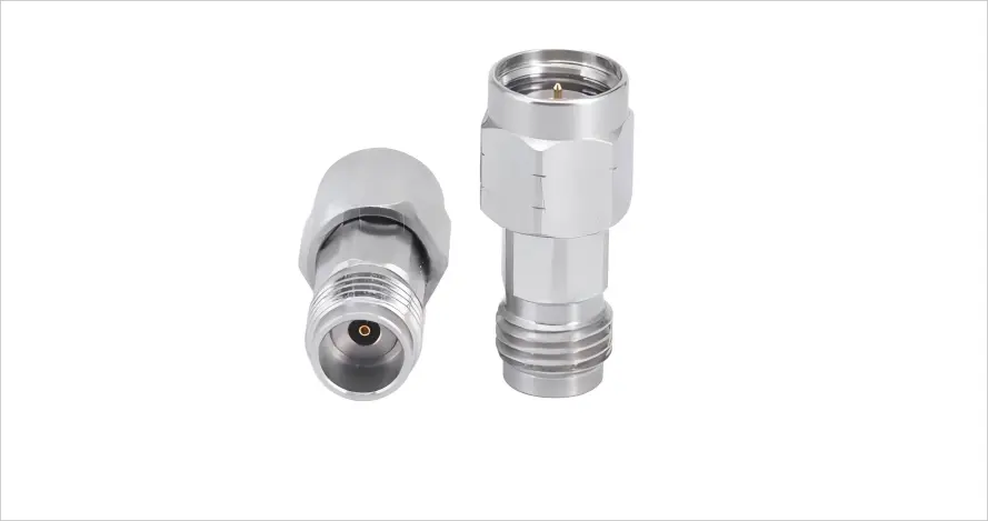
Key Advantages and Performance Features of 1.85 RF Attenuators
High-frequency 1.85 RF attenuators must balance multiple performance parameters to satisfy demanding application requirements. The engineering trade-offs between frequency response, power handling, and physical size determine component suitability for specific projects.
Superior Frequency Response and Electrical Specifications
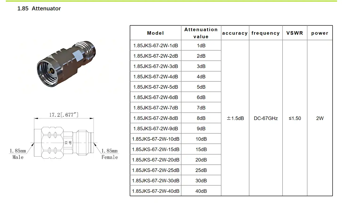
Precision millimeter-wave attenuators over the complete DC-to-67 GHz band provide signal management for applications from satellite communications to radar testing. The voltage standing wave ratio (VSWR) is less than 1.65 throughout the whole frequency range, showing good impedance matching and low signal reflection. The lower the VSWR, the lower the uncertainty of measurement and the better the performance of the system.
What distinguishes premium attenuators from cheap equivalents is the insertion loss requirement. Parasitic losses decrease the signal quality and diminish the system dynamic range beyond the nominal attenuation value. Good devices reduce these losses by careful selection of materials and production procedures. Our implemented solution keeps insertion loss within very tight tolerances; thus, the real signal loss equals the prescribed attenuation value on all working frequencies.
The power-handling capacity is the highest signal level that an attenuator can handle before its performance is degraded or damaged. The average power rating of 2 watts is enough for most test and measurement applications. Peak power capability of up to 200 watts is available for pulsed radar and communication systems. This implies that the power capability is derated to 0.5 watts at the highest operational temperature of 125°C. In increased ambient circumstances, temperature derating is required.
Comparing 1.85mm to Alternative Connector Types
The RF and microwave industry has several different connection standards, and each has its benefits for a certain frequency range or application. The 1.85mm format has a crucial place in this ecosystem, delivering possibilities that span a range of design contexts.
N-type connections are still widely used below 18 GHz, with a sturdy mechanical design and affordable prices. But their increased physical size and poor frequency response make them unsuitable for millimeter-wave operations. At frequencies exceeding 20 GHz, engineers must migrate to precision connection families to provide acceptable electrical performance.
The 2.92mm connection (also known as a K connector) provides a usable frequency response to 40 GHz for many microwave applications. Slightly bigger interface dimensions than those of 1.85mm kinds offer increased endurance for applications with numerous connection cycles. Many manufacturers of test instruments require 2.92 mm ports for equipment below 40 GHz frequencies.
The 1.85mm connection is used in situations where performance is more than 40 GHz. The lowered interface size preserves the tight tolerances necessary for successful operation at 67 GHz. The 2.4mm connection goes to 50 GHz frequency capabilities, giving another intermediate choice. However, the wider frequency coverage of the 1.85mm size makes it the more popular option for engineers who want to have the most flexibility across a range of projects and frequency bands.
Material Construction and Environmental Durability
Harsh working conditions need components that can tolerate severe temperature, vibration, and repetitive mechanical stress. The passivated stainless steel enclosure offers corrosion resistance and electromagnetic shielding, protecting the internal components from environmental contamination and external interference. This material selection provides consistent performance in industrial environments, outdoor installations, and mobile test setups.
The contact surfaces are gold-plated to prevent oxidation and to provide low contact resistance throughout the life of the component. Gold-plated connections will retain their electrical functionality over long storage periods, while bare copper or silver finishes will tarnish over time. The 500 mate/demate cycle rating makes it ideal for applications that need repeated reconfigurations without sacrificing connection quality or electrical standards.
Operating temperature ranges from -55C to 125C, ideal for aerospace, military, and industrial applications where ordinary commercial parts would not survive. Dielectric materials such as polyetherimide (PEI) have steady electrical characteristics across the whole temperature range, and hence provide constant attenuation levels irrespective of the ambient circumstances. This thermal resilience is especially useful for outdoor telecommunication systems and automotive test applications with considerable temperature changes.
Best Practices for Using and Installing a 1.85 RF Attenuator
Proper installation and handling techniques will maximise component performance and service life. Good approaches are known for avoiding typical difficulties that reduce measurement accuracy and destroy costly test equipment.
Connection and Torque Specifications
Precision connections are threaded on with regulated tension to provide the best electrical contact without mechanical harm. Over-tightening distorts the connection interfaces, decreasing the VSWR and perhaps causing permanent deformation. Under-tightening causes intermittent connections, poor repeatability, and increased signal reflection.
Torque levels are defined by the manufacturers for their connection types, often 8 to 12 inch-pounds for 1.85mm interfaces. They consistently make connections that satisfy these standards using a calibrated torque wrench. Engineers must ensure connectors are clean before mating to remove any pollution that might inhibit appropriate contact or introduce foreign atoms to the interface.
The direction of the signal is important when placing 1.85 RF attenuators in a test setup. The input port is subjected to greater power levels, and the output port is connected to sensitive instruments or system components. If this orientation were reversed, the equipment may be subjected to extreme amounts of signal, which may cause damage or measurement inaccuracies. Complex test setups are less prone to installation errors due to clear labelling of the ports.
Calibration and Performance Verification
Measurement accuracy is ensured by regular calibration of test systems using attenuators as reference standards. Annual calibration intervals will be sufficient for most laboratory situations, whereas tough industrial circumstances may need semi-annual verification. Documentation of calibration findings ensures traceability to national standards to fulfil quality system requirements in regulated businesses.
Power meters and spectrum analysers may be used for performance monitoring to identify deterioration before it impacts the validity of the measurement. The actual attenuation levels may be compared with the specifications to identify components that need to be replaced or recalibrated. This proactive method eliminates inaccurate test results and the expensive troubleshooting that occurs from undiscovered component failures.
Environmental controls protect attenuators from environmental circumstances outside their design requirements. Operating within the authorised temperature range will keep the power handling capacity sufficient and avoid heat damage to internal components. Additional monitoring might be helpful in confirming safe operating margins when applications are nearing maximum power ratings.
Selecting and Procuring the Right 1.85 RF Attenuator for Your Needs
Successful component procurement balances technical specifications, supplier reliability, and total cost of ownership. Engineering teams must evaluate multiple factors to identify optimal solutions for their specific applications.
Technical Specification Alignment
The frequency range represents the primary specification determining attenuator suitability. Applications operating exclusively below 40 GHz might consider more economical connector types, while multi-band systems benefiting from a single component covering DC to 67 GHz justify the precision 1.85mm format. Matching frequency specifications to actual requirements avoids paying for unnecessary performance margins.
Attenuation value selection depends on system dynamic range requirements and the signal levels present in specific test configurations. Common values including 3, 6, 10, and 20 dB suit most applications, with higher values available for specialized scenarios. Engineers often maintain an assortment of attenuation values, allowing flexible configuration of test setups for various measurement needs.
Power handling specifications must accommodate the maximum signal levels present in the application, including safety margins for unexpected conditions. Continuous wave (CW) and peak power ratings both require consideration, particularly in pulsed systems where instantaneous power levels significantly exceed average values. Thermal management becomes critical when operating near maximum power specifications, potentially requiring heat sinking or airflow enhancement.
Supplier Evaluation and Quality Assurance
Reputable suppliers provide documented performance specifications, calibration certificates, and material traceability supporting quality requirements. Procurement managers should verify supplier capabilities, including testing facilities, quality management systems, and technical support resources. These factors significantly impact long-term satisfaction beyond initial purchase price considerations.
After-sales support distinguishes premium suppliers from commodity vendors. Access to technical assistance helps engineers troubleshoot installation challenges, interpret specifications, and optimize system performance. Responsive support reduces downtime when questions arise during critical project phases, protecting schedule commitments and budgets.
Warranty coverage reflects manufacturer confidence in product reliability and provides financial protection against premature failures. Standard warranty periods range from one to three years, with extended coverage available for applications demanding maximum uptime. Understanding warranty terms, including coverage limitations and claim procedures, prevents surprises if component issues occur.
Troubleshooting and Technical Support for 1.85 RF Attenuators
Even if the equipment is designed and installed correctly, it may have performance problems that need to be diagnosed in a methodical way. Understanding typical failure types and how to troubleshoot them can save system downtime.
Common Issues and Diagnostic Approaches
Signal deterioration is shown as insertion loss over defined levels. Potential causes include contamination of contacts or a breakdown of internal components. Comparison of the readings to baseline calibration data determines the severity of the deterioration. If contamination is the issue, performance may typically be restored by cleaning the connection interfaces. Component replacement is a good choice if the decline is constant after numerous cleanings.
Over-torquing or mishandling may cause mechanical damage that permanently impairs connection function. Visual Inspection exposes distorted interfaces, bent pins, or fractured dielectric materials that need component replacement. Proper handling practices are less expensive than regular replacements to prevent mechanical damage.
Intermittent connections cause measurement repeatability difficulties, which then frustrate troubleshooting attempts. These challenges usually result from worn connections near the limits of their mate/demate cycle, or contamination that prevents continuous contact. You may determine whether the fault is with the attenuator or the mating connections by systematically cycling the connection and observing performance.
Accessing Technical Resources and Support
Documentation like datasheets, application notes, and installation guidelines may help ensure components are used properly. Manufacturers that provide in-depth technical information prove that they care about success, not just selling things. These documents allow engineers to maximise performance and avoid typical mistakes in system integration.
Documentation will only get you so far, and there is a lot of value in having direct technical help from experienced applications engineers. Responsive suppliers have team members who can respond to difficult concerns concerning specifications, application needs, and troubleshooting procedures. This information is especially useful in the creation of new products when atypical demands push the limits of normal components.
Conclusion
The need for accurate signal management is inherent in current RF and microwave systems. The 1.85 RF attenuator provides the critical capabilities from test instruments to sophisticated communication infrastructure. Knowledge of attenuator parameters, suitable installation methodologies, and supplier selection criteria enables engineering teams to make educated choices that promote project success. Engineers working with millimetre wave frequencies will find 1.85mm attenuators to be useful tools due to their broad frequency coverage, outstanding electrical performance, and rugged mechanical construction. Working with established suppliers that are capable of providing quality goods and full support enables procurement managers to provide their organisations with access to the precise components that are critical to competitive advantages in challenging marketplaces.
FAQ
1. What frequency range do 1.85 RF attenuators cover?
Precision 1.85 RF attenuators operate from DC through 67 GHz, supporting applications across microwave and millimeter-wave bands. This broad frequency coverage enables engineers to use a single component type across multiple projects and frequency allocations, simplifying inventory management and standardizing test procedures.
2. How do I select the correct attenuation value?
Attenuation value selection depends on system dynamic range requirements and the signal levels requiring control. Analyze your maximum signal levels and the desired output power to determine the necessary attenuation. Common values, including 6, 10, and 20 dB, suit most test applications, while specialized scenarios may require different values available from component suppliers.
3. What torque specifications apply to 1.85mm connectors?
Proper installation requires torque values between 8 and 12 inch-pounds applied with a calibrated torque wrench. This controlled tightening achieves optimal electrical contact while preventing mechanical damage that degrades performance. Always verify connector cleanliness before mating to ensure reliable connections and accurate measurements.
4. Can attenuators handle both continuous and pulsed signals?
Quality attenuators specify both average and peak power ratings, accommodating different signal types. Average power ratings around 2 watts support continuous-wave signals, while peak power capabilities reaching 200 watts handle pulsed systems. Verify that both specifications match your application requirements to prevent component damage.

Partner with Chuangyu for High-Performance RF Solutions
Shaanxi Chuangyu Electronic Technology Co., Ltd. specializes in precision millimeter-wave components serving demanding applications across telecommunications, aerospace, medical, and test instrumentation industries. Our 1.85 RF attenuators deliver the exceptional performance and reliability engineering teams require for projects operating at frequencies approaching 70 GHz. With manufacturing capabilities producing 500,000 RF components annually, we maintain the production capacity supporting both prototype development and volume production requirements.
Our Xi'an facility integrates design, manufacturing, and testing operations, ensuring consistent quality throughout the production process. Nearly two decades of RF component expertise inform our manufacturing processes and quality control procedures, delivering products meeting international standards. We understand the challenges procurement managers face in balancing technical specifications, delivery schedules, and budget constraints when sourcing precision components.
Whether your project requires standard catalog products or custom solutions tailored to unique specifications, our technical team provides application support, ensuring optimal component selection. As a trusted 1.85 RF attenuator supplier, we offer comprehensive technical documentation, responsive customer service, and competitive pricing to support your project's success. Contact our team at chuangyuwz01@cymicrowave.com to discuss your requirements and discover how our precision components enhance your system performance.
References
1. Pozar, David M. Microwave Engineering, 4th Edition. Hoboken: John Wiley & Sons, 2011.
2. Bahl, Inder J. Lumped Elements for RF and Microwave Circuits. Boston: Artech House, 2003.
3. Sayre, Charles W. Complete Wireless Design, 2nd Edition. New York: McGraw-Hill, 2008.
4. IEEE Standard 287-2007. IEEE Standard for Precision Coaxial Connectors at RF, Microwave and Millimeter-wave Frequencies. New York: Institute of Electrical and Electronics Engineers, 2007.
5. Whitaker, Jerry C. The RF Transmission Systems Handbook. Boca Raton: CRC Press, 2002.
6. Rizzi, Peter A. Microwave Engineering: Passive Circuits. Upper Saddle River: Prentice Hall, 1988.
