- English
- French
- German
- Portuguese
- Spanish
- Russian
- Japanese
- Korean
- Arabic
- Greek
- German
- Turkish
- Italian
- Danish
- Romanian
- Indonesian
- Czech
- Afrikaans
- Swedish
- Polish
- Basque
- Catalan
- Esperanto
- Hindi
- Lao
- Albanian
- Amharic
- Armenian
- Azerbaijani
- Belarusian
- Bengali
- Bosnian
- Bulgarian
- Cebuano
- Chichewa
- Corsican
- Croatian
- Dutch
- Estonian
- Filipino
- Finnish
- Frisian
- Galician
- Georgian
- Gujarati
- Haitian
- Hausa
- Hawaiian
- Hebrew
- Hmong
- Hungarian
- Icelandic
- Igbo
- Javanese
- Kannada
- Kazakh
- Khmer
- Kurdish
- Kyrgyz
- Latin
- Latvian
- Lithuanian
- Luxembou..
- Macedonian
- Malagasy
- Malay
- Malayalam
- Maltese
- Maori
- Marathi
- Mongolian
- Burmese
- Nepali
- Norwegian
- Pashto
- Persian
- Punjabi
- Serbian
- Sesotho
- Sinhala
- Slovak
- Slovenian
- Somali
- Samoan
- Scots Gaelic
- Shona
- Sindhi
- Sundanese
- Swahili
- Tajik
- Tamil
- Telugu
- Thai
- Ukrainian
- Urdu
- Uzbek
- Vietnamese
- Welsh
- Xhosa
- Yiddish
- Yoruba
- Zulu
Millimeter-wave engineers and procurement specialists must choose the right waveguide-to-coaxial transition component. In space-constrained RF designs, an Orthogonal waveguide coaxial converter connects waveguide transmission lines with coaxial cables at perpendicular orientations for effective signal routing. The appropriate choice affects system insertion loss, return loss, power handling capacity, and measurement accuracy, especially in systems over 75 GHz where even tiny impedance mismatches degrade performance. This comprehensive guide helps engineering teams and procurement managers source precision components for radar systems, satellite ground stations, semiconductor test equipment, and aerospace instrumentation by addressing technical, commercial, and operational factors.
Key Criteria for Selecting Orthogonal Waveguide Coaxial Converters
Procurement decisions hinge on matching converter specifications to system requirements across multiple dimensions. Engineers must balance electrical performance, mechanical robustness, environmental resilience, and commercial viability when evaluating supplier offerings.
Electrical Performance Parameters
Converters must cover the working band plus margin. WR10 converters operate at 75-110 GHz; however, band edges restrict bandwidth. Instead of nominal waveguide bands, measure insertion loss across frequencies. Network matching is needed for smooth 30+ GHz broadband applications.
Decibels affect the system link budget and measurement dynamic range. Premium converters have 0.6 dB mid-band loss, whereas cheap ones have 1.5-2.0. Cascaded measurement transitions increase variances. Thermal drift reduces calibration accuracy in outdoor and high-duty-cycle applications; therefore, insertion-loss temperature stability is crucial.
Return loss >20 dB reduces impedance discontinuity and standing wave ratio, increasing measurement repeatability. High-power gearboxes protect source components from reflected power with good return loss. Transmitter protection circuits may fail, although receiver return loss below 15 dB may function.
Material Quality and Construction Standards
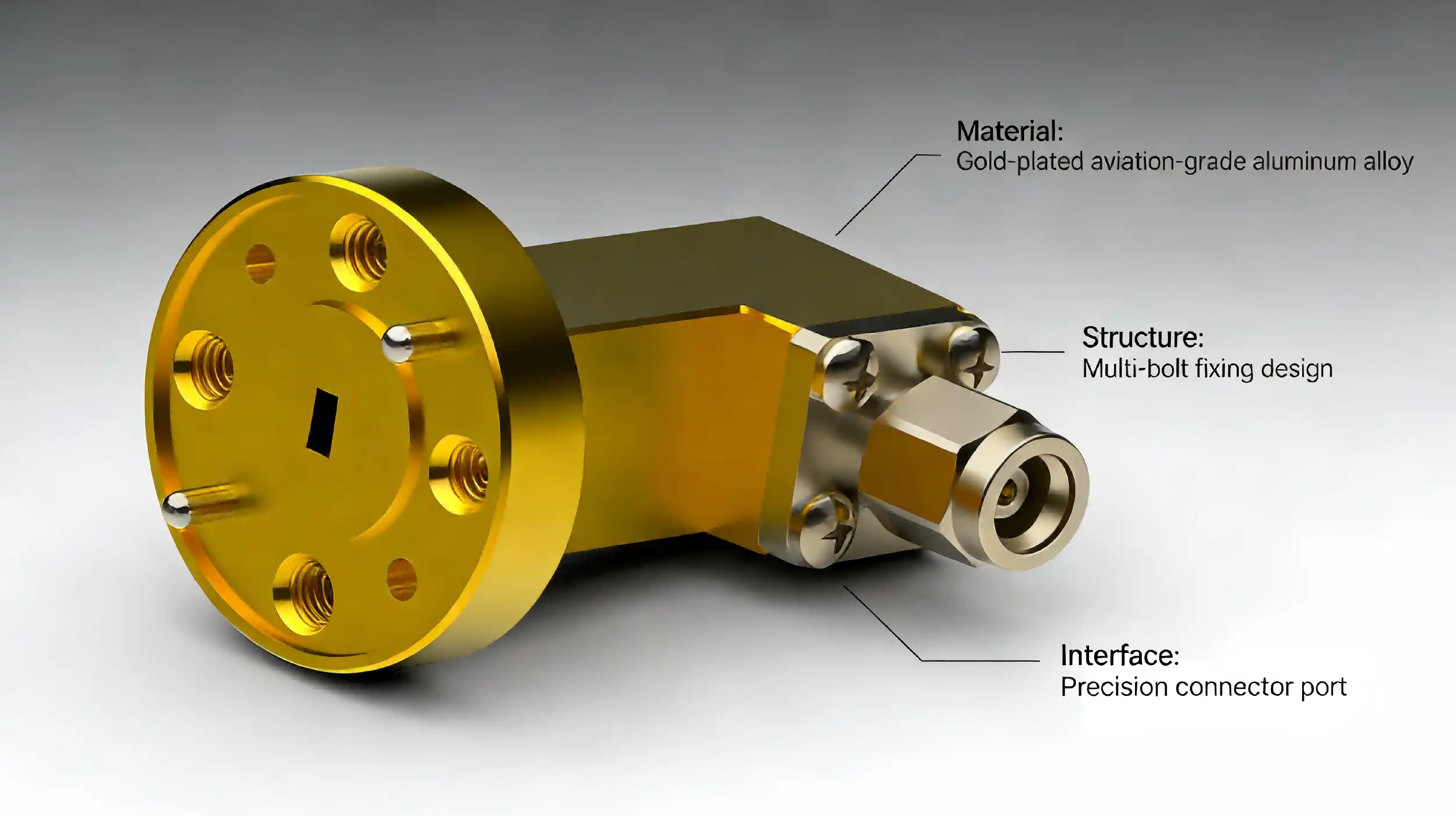
The Orthogonal waveguide coaxial converter body material affects thermal conductivity, weight, and machinability. Brass offers excellent electrical conductivity and ease of precision machining at a moderate cost, making it standard for laboratory instruments. Aluminum reduces weight for aerospace applications but requires careful surface treatment to achieve comparable electrical performance. Gold plating on mating surfaces prevents galvanic corrosion when interfacing with stainless steel waveguide flanges and ensures stable contact resistance through thousands of connection cycles.
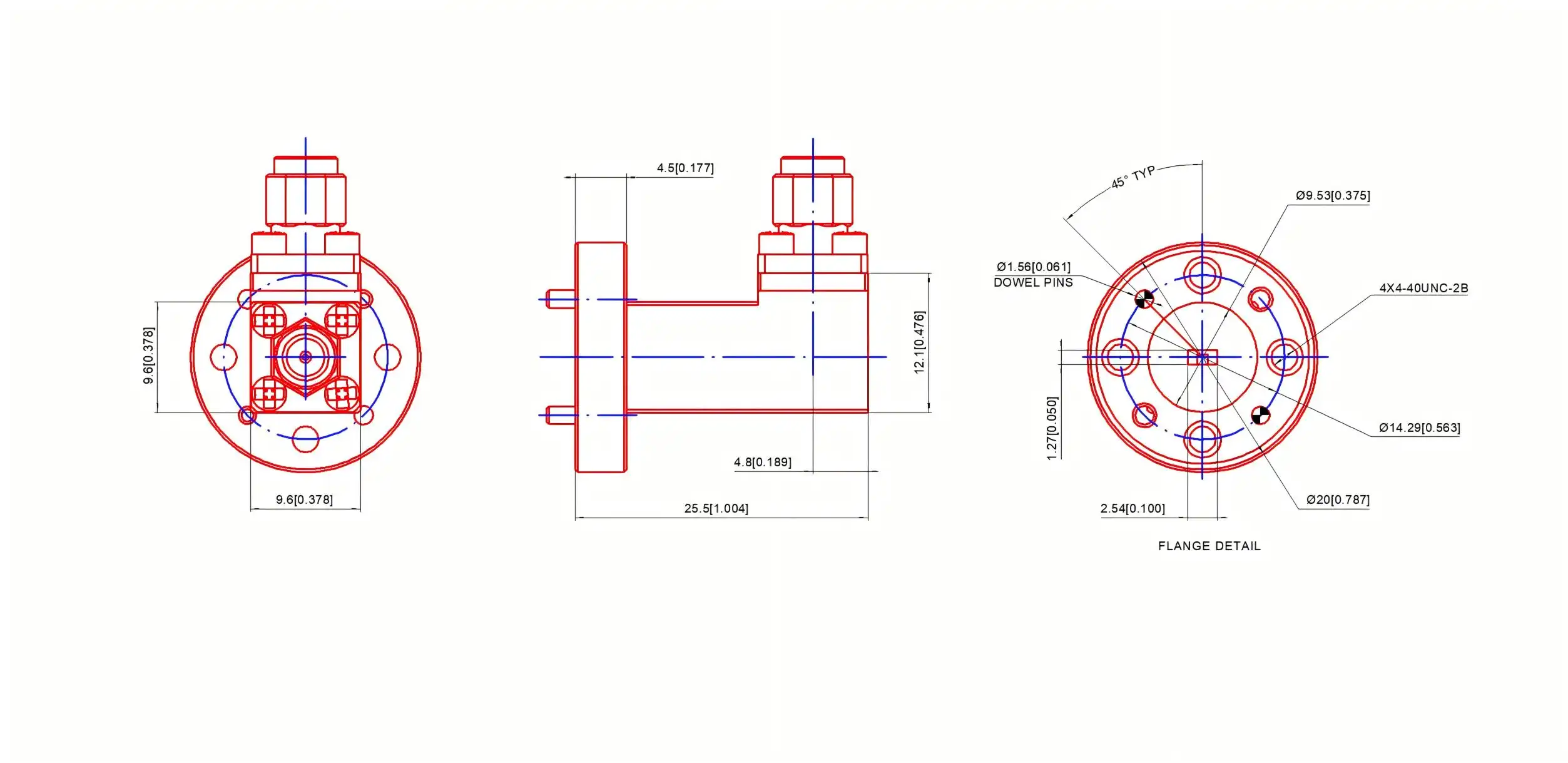
Flange flatness and surface finish directly influence RF sealing effectiveness. Premium converters maintain flange flatness within 0.013 mm and surface roughness below 1.6 μm Ra, ensuring consistent gasket compression and RF contact when torqued to specification (typically 0.45±0.02 Nm for WR10 interfaces). Internal dimensional tolerances affect cutoff frequency and higher-order mode suppression—variations exceeding 0.3% can shift band edges by several gigahertz.
Compatibility and Integration Considerations
Waveguide flange type should match hardware—UG-387 dominates WR10, although regional variances exist. Mating cables must match coaxial connection gender (male/female) and thread type (standard/non-standard pitch). Some converters with detachable coaxial adapters allow field reconfiguration between connection families without replacement.
Installation: Orthogonal converters may be mounted in several orientations, but the coaxial port must leave the waveguide. Flange thickness and mounting hole configurations affect bracket-waveguide assembly integration. Restricted-access equipment may require converters with captive screws or quick-release mechanisms.
Moisture cannot enter hermetically sealed aircraft platform pressure-variant and external installations. MIL-STD-202 shock and vibration converters resist travel and deployment. Thermal cycling certification provides indoor heating throughout seasonal temperature changes and operational duty cycles.
Comparing Orthogonal Waveguide Coaxial Converters with Alternatives
Understanding how orthogonal configurations compare to alternative transition approaches clarifies when this design offers distinct advantages versus situations where simpler solutions suffice.
Orthogonal Versus Inline Transitions
Inline waveguide-to-coax adapters mount along the waveguide's longitudinal axis, offering slightly lower insertion loss (typically 0.1-0.3 dB better) due to a more direct field-coupling geometry. However, their axial protrusion creates spatial conflicts in compact assemblies where multiple converters mount to adjacent waveguide sections. Orthogonal designs excel when coaxial cables must run parallel to waveguide runs or when mounting bulkheads require perpendicular exits.
Thermal performance differs between configurations. Inline adapters concentrate heat dissipation along the waveguide axis, potentially creating hot spots in high-power applications. The orthogonal geometry distributes thermal loads across larger surface areas, improving heat-sinking capability when the coaxial port bolts to chassis panels serving as thermal pathways. This advantage proves significant in radar transmitters and high-power test systems.
Performance Data from Leading Manufacturers
Leading converter manufacturers produce W-band converters with 0.5-1.2 dB insertion loss and 16-23 dB return loss. Premium European manufacturers use precision machining and gold plating to achieve 0.6 dB average loss and 22 dB return loss at 40-60% higher prices than Asian competitors. Commercial applications benefit from Chinese RF component manufacturers like Shaanxi Chuangyu Electronic Technology's competitive specs at 0.8-1.0 dB insertion loss and 18 dB return loss.
Broadband performance varies significantly. Designs targeted for small 10-15 GHz spans achieve outstanding flatness (±0.3 dB) in the waveguide band. Broadband versions encompassing the 75-110 GHz range reduce flatness (±0.8 dB ripple) but remove the requirement for band-specific converters. The application needs to determine the trade-off.
Innovation Trends and Design Evolution
Recent advances focus on extending power handling through improved thermal design, incorporating aluminum nitride insulators and optimized conductor cross-sections. Some manufacturers now offer field-replaceable coaxial interfaces, allowing users to swap between 1.0 mm, 1.85 mm, and 2.4 mm connectors without purchasing multiple complete assemblies. Modular designs featuring removable waveguide sections simplify integration into custom assemblies while maintaining performance comparable to monolithic constructions.
Emerging materials, including low-loss dielectrics and surface treatments, push insertion loss below 0.5 dB at upper millimeter-wave bands. Additive manufacturing techniques enable complex internal geometries impossible with traditional machining, though cost-effectiveness remains limited to specialized low-volume applications. These innovations trickle down to commercial products as manufacturing processes mature.
Procurement Considerations for B2B Buyers
Effective sourcing balances technical performance against commercial realities, including supplier reliability, customization capabilities, and total cost of ownership.
Identifying Reputable Suppliers and Manufacturers
Established RF component wholesalers compare and buy from numerous manufacturers. Customisation and bulk pricing benefit from direct manufacturer interaction. Assess vendors based on ISO 9001 certification, calibration traceability to national standards labs, and documented quality control methods, such as network analyser testing of every shipping device.
Customer references from your industry sector reveal real-world performance and support quality. Aerospace and defence suppliers have more process controls and documentation than commercial suppliers, but this comes with a price. Shaanxi Chuangyu Electronic Technology, with over two decades of RF manufacturing expertise and sophisticated production facilities, delivers components that satisfy worldwide requirements at low prices.
Commercial Factors and Supply Chain Planning
Unit prices vary from $150 to $800 based on specs, materials, and supplier status. After 10 units, volume savings activate with tiered pricing at 25, 50, and 100+ units. Custom setups cost 20-40% more than catalogue goods but avoid performance trade-offs.
Minimum Order Quantities: Catalogue goods ship as singles; however, bespoke designs may need 5-10 units to justify setup. Avoid miscommunication by clarifying MOQ needs early in sourcing conversations. For assessment before volume purchases, several manufacturers provide prototype numbers at near-production prices.
Lead times and availability: Standard Orthogonal waveguide coaxial converters from established vendors ship in 2-4 weeks, whereas unique designs take 6-10 weeks to develop, prototype, and validate. Lead times might be unpredictable due to coaxial connection or specialised alloy limitations. Maintain numerous qualified vendors to reduce crucial program supply interruptions.
Customization Services and After-Sales Support
Complex system architectures may demand converters with non-standard flange orientations, special coaxial connectors, or environmental sealing beyond catalog specifications. Manufacturers with in-house design capabilities and flexible manufacturing processes accommodate these requirements, though detailed requirement documentation streamlines the customization process. Request pre-production samples for validation testing before committing to production quantities.
Warranty coverage typically spans 12-24 months against manufacturing defects, with some suppliers offering extended protection plans. Technical support quality varies significantly—premium suppliers provide application engineering assistance during integration, while budget alternatives may offer limited post-sale engagement. Availability of test data specific to your unit (S-parameters, power handling verification) enhances confidence in performance claims and facilitates system-level troubleshooting.
Ensuring Long-Term Value: Best Practices and Recommendations
Maximizing converter investment extends beyond initial selection to encompass proper usage, maintenance, and strategic planning aligned with evolving technology landscapes.
Application-Specific Selection Strategies
Measurement and Test Systems: Use converters with >20 dB return loss and temperature-stable insertion loss. Replaceable connectors help labs reorganise cables. Budgets should emphasise metrology-grade components for key reference routes and allow mild performance losses on less critical links.
Power management and environmental sealing are crucial for communication and radar systems. Hermetic, thermally efficient outdoor systems fail less. Mobile platform vibration-resistant parts. Consider overall ownership cost, including maintenance, not just purchase cost.
Converters for many connections accelerate prototyping and development. To save architectural research expenditures, consider vendors offering returnable evaluation kits. Fast lead times are better than modest performance variances for prototype timelines that affect program deadlines.
Usage Specifications and Operational Guidelines
Good installation prolongs converter life. Use lint-free wipes and isopropyl alcohol to clean mating surfaces of dust and oxides before attaching. Carefully align waveguide flanges and tighten mounting screws to the specified torque (0.45±0.02 Nm for WR10) in a cross pattern. Avoid torque-induced flange deformation and RF leakage sealing gaps.
Millimeter-wave components have lower power thresholds than lower-frequency components due to smaller conductors and greater current density. Dielectric breakdown or conductor vaporisation may cause catastrophic failure at high power. Pulsed apps must respect peak and average power.
Safe environmental operating ranges include temperature and humidity. Beyond -20°C to +50°C, dimensional changes decrease electrical performance and accelerate material breakdown. Without adequate sealing, mating surfaces and internal probe structures corrode in high humidity, reducing insertion and return loss. Cover crucial interfaces during storage and transport with dust coverings.
Maintenance and Care
Maintenance increases converter life and provides accurate measurements. After 50 connection cycles or quarterly, clean coaxial and waveguide interfaces using connector cleaning kits. Flange burrs, nicks, or deformation indicate improper torque or impact damage. Replace deteriorating converters to prevent downstream component damage and measurement errors.
Millimeter-wave components are expensive; thus, storage is crucial. Keep humidity below 60% and temps between 15-25°C to prevent rusting. Dust covers on coaxial and waveguide ports protect sealing surfaces during installation. Label inventory with the latest calibration date and rotate and replace using cycle count.
Standard network analyser measurements check specification compliance and detect degradation before it impacts system operation. Acceptance testing: record insertion loss, return loss, and frequency response; repeat annually or after 500 connection cycles. Trending this data reveals maintenance and replacement wear.
Future-Proofing and Strategic Considerations
Converters should follow updated standards as technology improves equipment. Modules with field-replaceable interfaces for many coaxial connector types enable migrations from 2.92 mm to 1.0 mm topologies without converter replacement. A bandwidth buffer above current needs permits frequency expansions when spectrum allocations and system capabilities change.
Partnering with bespoke manufacturers helps companies handle unanticipated demands. Design help and quick prototyping vendors accelerate product development when new challenges occur. Standardised components reduce unit costs, but customised solutions improve system performance and justify price increases via functionality or integration.
Diversifying providers decreases supply chain risks without interrupting purchases. Qualification of two important component sources ensures the continuation of production or allocation. Standardising internal interfaces and requirements enhances supplier options and simplifies certification.
Conclusion
Electrical parameters, mechanical build quality, and supplier capabilities must be considered when selecting a waveguide-to-coax transition device. The orthogonal layout has benefits in space-constrained locations and performs similarly to inline alternatives when correctly planned and built. Orthogonal waveguide coaxial converter features must meet application requirements—measurement precision for test equipment, power handling for gearbox systems, and environmental resilience for field installations—to succeed in procurement. Using recognised manufacturers with precise RF component knowledge, thorough quality processes, and rapid technical support assures long-term performance. Strategic sourcing takes into account urgent requirements, customisation flexibility, supply chain stability, and emerging technological standards.
FAQ
1. What frequency ranges do orthogonal waveguide coaxial converters typically support?
These converters operate across standard waveguide bands determined by their waveguide size. WR10 variants cover 75-110 GHz, WR15 spans 50-75 GHz, and WR28 addresses 26.5-40 GHz. Effective bandwidth within each range depends on impedance matching design—some optimize for full band coverage with modest ripple, while others achieve exceptional flatness across narrower spans. Coaxial connector selection also influences usable bandwidth, with 1.0 mm connectors supporting frequencies up to 110 GHz and 1.85 mm variants limited to approximately 67 GHz. Verify that your specific operating frequencies fall well within the converter's rated range with adequate margin.
2. When should I consider custom converter designs rather than catalog products?
Custom designs prove worthwhile when standard offerings create system compromises requiring multiple adapters or workarounds. Non-standard flange orientations, special environmental sealing requirements, unusual coaxial connector types, or integration into complex mechanical assemblies justify customization. Applications demanding exceptional performance (insertion loss below 0.6 dB, return loss exceeding 23 dB) may benefit from optimization for narrower bandwidths than catalog broadband variants. Volume requirements of 25+ units typically offset custom design costs through eliminated adapters and improved system performance, while smaller quantities favor adapting standard products unless critical performance gaps exist.
3. What integration challenges commonly arise with these components?
Torque specifications require careful attention—over-tightening deforms flanges while insufficient torque creates RF leakage paths. Coaxial cable stress at the connector risks mechanical damage in vibration environments without adequate strain relief. Thermal expansion mismatches between converter materials and mounting structures create stress during temperature cycling. Waveguide mode purity affects performance; higher-order modes generated by upstream discontinuities cause unpredictable insertion loss and return loss degradation. Proper grounding and RF shielding prevent interference in sensitive measurement applications. Working with experienced suppliers provides application guidance addressing these practical integration concerns.
Partner with Chuangyu for Premium Waveguide Transition Solutions
Shaanxi Chuangyu Electronic Technology delivers precision-engineered Orthogonal waveguide coaxial converters manufactured to exacting international standards at our modern Xi'an production facility. Our WR10 converters feature robust brass construction with selective gold plating, 1.0 mm male coaxial interfaces, and optimized impedance matching, achieving <0.8 dB typical insertion loss across 75-110 GHz. As an established RF coaxial converter manufacturer serving aerospace, telecommunications, semiconductor test, and defense sectors, we combine nearly two decades of manufacturing expertise with responsive customization capabilities and comprehensive quality assurance.
Our engineering team supports your integration challenges through detailed application consultation, custom flange orientations, and specialized environmental sealing when standard configurations prove inadequate. Competitive pricing structures accommodate both prototype quantities and production volumes, with lead times shortened through optimized supply chain management. Contact our technical specialists at chuangyuwz01@cymicrowave.com to discuss your specific requirements, request detailed performance data, or obtain quotations.
References
1. Marcuvitz, N. (1986). Waveguide Handbook. Institution of Engineering and Technology Press.
2. Balanis, C. A. (2012). Advanced Engineering Electromagnetics (2nd ed.). Wiley.
3. IEEE Standard 148-1997. IEEE Standard for Waveguide Flanges.
4. Pozar, D. M. (2011). Microwave Engineering (4th ed.). Wiley.
5. Collin, R. E. (2001). Foundations for Microwave Engineering (2nd ed.). Wiley-IEEE Press.
6. MIL-PRF-39012E. Performance Specification: General Specification for Waveguide and Waveguide Components, Radio Frequency, Rigid and Flexible.
