- English
- French
- German
- Portuguese
- Spanish
- Russian
- Japanese
- Korean
- Arabic
- Greek
- German
- Turkish
- Italian
- Danish
- Romanian
- Indonesian
- Czech
- Afrikaans
- Swedish
- Polish
- Basque
- Catalan
- Esperanto
- Hindi
- Lao
- Albanian
- Amharic
- Armenian
- Azerbaijani
- Belarusian
- Bengali
- Bosnian
- Bulgarian
- Cebuano
- Chichewa
- Corsican
- Croatian
- Dutch
- Estonian
- Filipino
- Finnish
- Frisian
- Galician
- Georgian
- Gujarati
- Haitian
- Hausa
- Hawaiian
- Hebrew
- Hmong
- Hungarian
- Icelandic
- Igbo
- Javanese
- Kannada
- Kazakh
- Khmer
- Kurdish
- Kyrgyz
- Latin
- Latvian
- Lithuanian
- Luxembou..
- Macedonian
- Malagasy
- Malay
- Malayalam
- Maltese
- Maori
- Marathi
- Mongolian
- Burmese
- Nepali
- Norwegian
- Pashto
- Persian
- Punjabi
- Serbian
- Sesotho
- Sinhala
- Slovak
- Slovenian
- Somali
- Samoan
- Scots Gaelic
- Shona
- Sindhi
- Sundanese
- Swahili
- Tajik
- Tamil
- Telugu
- Thai
- Ukrainian
- Urdu
- Uzbek
- Vietnamese
- Welsh
- Xhosa
- Yiddish
- Yoruba
- Zulu
Installing high-frequency coaxial connectors on sensitive printed circuit boards demands precision, patience, and proper technique. The GPO RF connector, an ultra-small push-in type interface designed for millimeter-wave applications up to 40GHz, presents unique challenges due to its compact footprint and delicate pin structures. When R&D engineers or hardware designers approach PCB assembly with these miniature components—featuring center spacings as tight as 4.3mm—the margin for error narrows significantly. Damage risks include pad lifting, trace fractures, and thermal stress from excessive soldering temperatures. Successfully mounting these connectors requires understanding their structural characteristics, preparing the PCB substrate correctly, controlling soldering parameters below 260°C, and verifying mechanical alignment within 0.2mm coaxiality tolerances to preserve signal integrity across DC-40GHz frequency ranges.
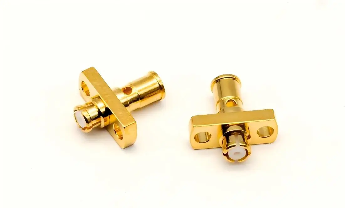
Common Challenges in Installing GPO RF Connectors on PCBs
Pad Lifting and Trace Damage Risks
The most common installation mistake is PCB pad adhesion failures, which are usually caused by too much mechanical force when placing the GPO RF connectors or uncontrolled heat cycles. FR-4 substrates, which are common in commercial RF boards, have different thermal expansion coefficients than copper traces. When soldering temperatures go above what is suggested or heating lasts longer than 3 to 5 seconds, the difference in temperature puts stress on the bond between the pad and the laminate. On high-frequency laminates like Rogers 4350B, pads with a diameter of 0.5 to 0.8 mm become especially weak. When pads are lifted, they cut off electrical connection, which means that expensive repairs or a new board have to be made.
Misalignment and Coaxiality Errors
At 40GHz frequencies, it's very hard to get the needed 0.2mm coaxial connection between the GPO RF connector's center pin and the PCB's microstrip trace. As little as 0.15 mm of movement on the side causes impedance changes that show up as return loss spikes in network analyzer sweeps. Blind-mate GPO RF connector designs can handle some misalignment during mating, but the positioning must be set precisely during the first PCB installation. Even though magnifying the view helps, a lot of engineers still use alignment tools or supports to keep things straight while they're soldering.
Thermal Damage to Insulation Materials
The PTFE (polytetrafluoroethylene) insulation in 086 series wires that are suitable, like SS405 or RG405, can handle short exposures to temperatures up to 260°C. Contact with soldering tools for longer than this amount of time melts the dielectric, which changes the characteristic impedance and makes loss worse. In the same way, the internal insulator of the GPO RF connector can break down if heat transfer from nearby solder joints isn't managed. Real-time monitoring with temperature-indicating crayons or infrared thermometers stops damage that can't be fixed and lowers VSWR performance across the operational bandwidth.
By knowing about these risks, procurement managers can choose the right tools and training programs, which lower the number of scrap pieces and protect the integrity of expensive millimeter-wave PCB assemblies.
Step-by-Step Guide to Installing GPO RF Connectors Safely on PCBs
Pre-Installation PCB Preparation
First, compare the PCB size to the GPO RF connector datasheet. Make sure the mounting hole diameters (usually 2.0 to 2.2 mm for M2 hardware) and pad measurements are correct. Clean the landing area with isopropyl alcohol to get rid of any leftover solder paste or oxidation films that make it hard for the material to stick. Under 10–20x magnification, look at the board for flaws that were there before: microcracking near vias, delamination at trace edges, or solder mask intrusions onto pad surfaces. These flaws might not lead to failures right away, but they get weaker when the connectors are being put together.
Connector Alignment and Fixturing Techniques
Place the GPO RF connector on top of the PCB footprint so that the center pin lines up with the microstrip launch structure. To keep the boards straight, use a precision alignment jig or a PCB stand. Deviations in angle greater than 2° cause mechanical stress to build up at the solder joints. Some engineers temporarily hold the GPO RF connector in place by applying low-temperature adhesive tape to the edges of the flange. This stops the connector from moving side to side while still letting it reach the solder pads. Check for coaxiality by looking at the center conductor's connection to the ground plane through the PCB's clearance hole. Make sure the spacing is uniform before you start soldering.
Controlled Soldering Process
Use a rosin-based, no-clean flux on the exposed pads sparingly so that it doesn't get on the internal insulators of the GPO RF connector. Choose a soldering iron with a temperature range of 245-255°C and use a chisel tip that is no bigger than 1.5 mm to focus the heat transfer and avoid long rest times. As you touch the iron to both the pad and the connector terminal at the same time, add 0.5 to 0.8 mm of solder wire (63/37 tin-lead or SAC305 lead-free alloy) until the joint forms a smooth, concave fillet. To keep heat from moving into the connection body, keep touch time to two to three seconds per joint. Don't use forced air to cool things down; this can cause thermal shock fractures in solder joints or PCB laminates.
Mechanical Fastening and Stress Relief
Once the RF interface is soldered, use the right tools to lock the GPO RF connector's flange. Usually, M2 screws torqued to 0.3 to 0.4 Nm work well. When you torque something too much, it deforms the PCB base or cracks the solder joints. When you torque something too little, it lets vibrations loosen the joints in the field. If the unit has a cable pigtail, like a GPO-KFB2 connected with an 086 series cable, make sure the cable is routed so that the minimum bending radius is less than 10 mm. To keep tensile loads from moving to the solder contact during handling or thermal cycling, place strain relief clips or sticky cable mounts 15 to 20 mm from the connection body.
Post-Installation Verification Procedures
Use magnification to check the quality of the solder joint visually; look for full wetting, no voids, and correct fillet geometry. To make sure there is continuity, measure the DC resistance between the center wire and the ground plane. It should read <0.5Ω, which includes the contact resistance. Do a sweep with a network analyzer from DC to the practical frequency limit to make sure the return loss meets design goals, which are usually -15dB across the band. Any strange events, like increases in VSWR, unexpected resonances, or changes in impedance, show that there were problems during installation that need to be fixed before the system can be put together.These organized steps are the basis for installing GPO RF connectors in a way that doesn't damage them. They protect expensive PCB investments and make sure that RF performance meets requirements.
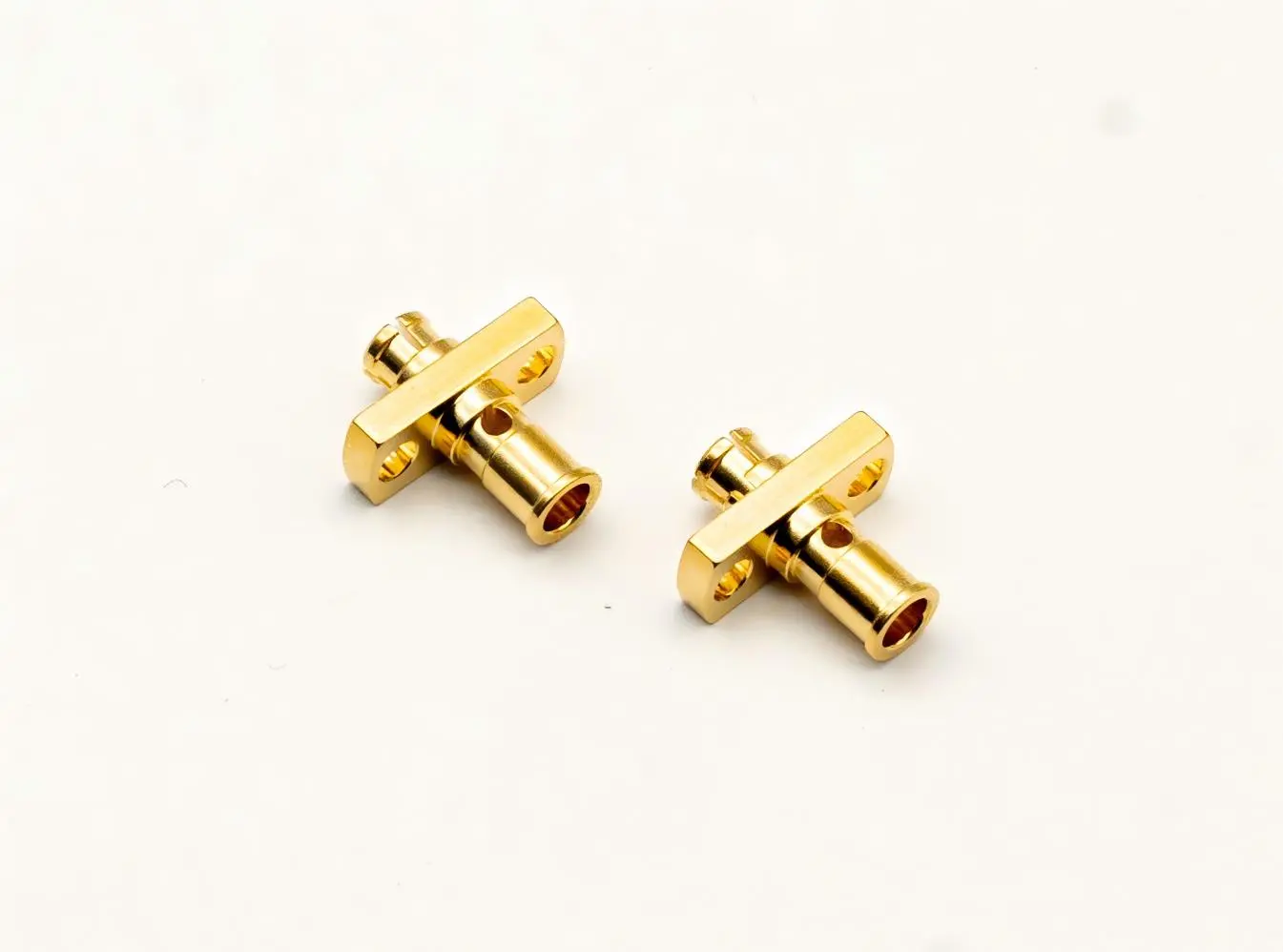
Best Practices and Tips to Maximize GPO RF Connector Lifespan and Performance
Handling and Storage Protocols
Keep unused GPO RF connectors in protective packaging against electrostatic discharge (ESD) in controlled-humidity environments (40–60% RH) to keep the gold-plated contacts from tarnishing. Before installing, let parts that have been stored in cold places slowly warm up to room temperature. This will keep condensation from forming, which speeds up corrosion. Handle GPO RF connectors by their edges instead of the delicate center pins. Beryllium copper contacts are strong, but they can permanently deform when subjected to forces greater than 50 grams. Document handling procedures for production staff to cut down on mistakes made by people that cause damage to machines.
Contamination Prevention Strategies
Particle contamination, even very small dust particles, stuck between the center wire and the outer shield causes impedance discontinuities that can be seen as return loss decline at millimeter-wave frequencies. When putting GPO RF connectors together, it's best to work in a Class 10,000 cleanroom or on a closed workbench with HEPA filtration. Use filtered compressed air or lint-free brushes wet with electronics-grade isopropyl alcohol to clean connections after they have been installed. Stay away from liquids that are based on petroleum, as they can damage PTFE insulators or leave behind films that change the dielectric qualities.
Periodic Inspection Schedules
For parts that are used in harsh conditions like aerospace thermal cycling, industrial vibration, or marine salt-fog exposure, check them every three months for corrosion, mechanical looseness, and contact resistance drift. The ≥500 mating cycle rating is based on lab conditions. In the field, where temperatures can change from -55℃ to +165℃, it may be more likely for wear to happen faster. By using predictive maintenance based on insertion loss trending, you can replace GPO RF connectors before they fail completely and cause problems with important systems.
Sourcing from Authorized Suppliers
There are a lot of fake GPO RF connectors in the supply chain. They are often made of low-quality materials (nickel plating instead of gold, brass instead of beryllium copper), which break easily when heated or strained mechanically. Only buy connectors from approved distributors or reputable makers who can provide certifications for the materials and proof of their origin. Check the validity by comparing the lot code to databases maintained by the maker. This extra care prevents performance problems that weaken system reliability and leave companies open to warranty claims. By following these tips, you can make parts last longer while still meeting the strict electrical performance requirements of millimeter-wave systems. This protects the big investments that come with making precise RF assemblies.
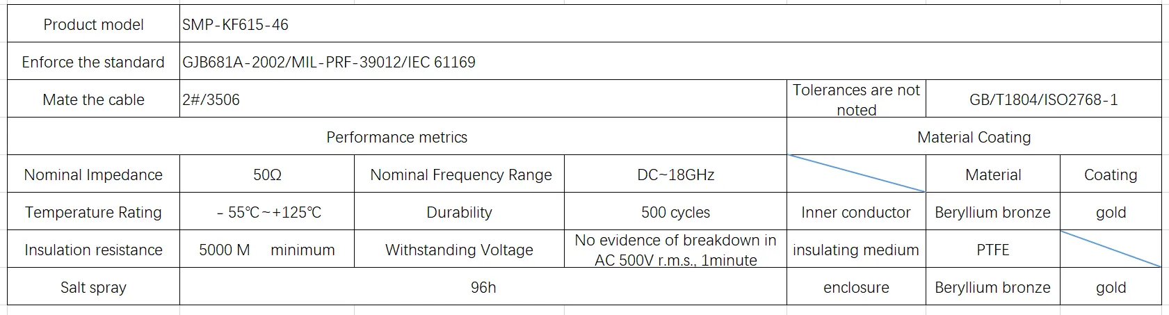
Procurement Considerations for Bulk GPO RF Connector Orders
Supplier Credential Verification
When looking at possible suppliers for large orders, give more weight to those that can show they are certified to ISO 9001:2015 and AS9100 for aerospace uses. Request test results that show how well the VSWR works across the given frequency range, along with material makeup certificates that prove the thicknesses of the gold plating and beryllium copper layers (usually 0.76 to 1.27 µm). Suppliers should give customers access to records that check the mechanical tolerances of measurements, especially important ones like the center pin width (0.51±0.013mm) and the placement of flange holes. Set up qualification rules that say sample batches must go through internal acceptance testing before GPO RF connector production orders can be approved.
Navigating Lead Times and MOQ Requirements
Standard GPO RF connectors made to industry footprints usually ship in 4 to 6 weeks. Customized versions with non-standard flange configurations or frequency-optimized insulators, on the other hand, take 10 to 12 weeks. Different suppliers have different minimum order quantities. For example, offshore manufacturers may need 500–1,000 pieces to lock in a price, while domestic suppliers that serve prototype markets will take orders as low as 25–50 units at higher prices. For project planning, keep 8–12 week buffers to account for the time it takes to ship goods internationally, clear customs, and inspect goods coming in.
Cost Optimization Strategies
You can get bulk discounts by combining multiple types of the same product into a single buy order. Savings usually start at 500 pieces, and there are more levels at 1,000 and 5,000 units. Instead of buying GPO RF connectors and cables separately, you might want to look into factory-assembled cable kits (GPO-KFB2 mated with 086 series cables). These already-put-together units save money on internal labor costs and performance risks from bad termination, and they usually reach cost parity around 200-unit amounts. Ask for landed cost quotes that include freight, taxes, and tariffs. This is especially important when buying from Asian makers that ship to U.S. facilities, as the total landed costs may be 15–25% higher than the initial unit price.
Quality Assurance and Compliance
Set acceptance criteria that are in line with MIL-STD-202 environmental testing protocols, especially Method 213 (random vibration) and Method 106 (humidity resistance). This will make sure that GPO RF connectors can handle operational stresses in aerospace and defense applications. When buying medical device assemblies, make sure that the suppliers are registered with ISO 13485 and can give you Declaration of Conformity paperwork that shows they follow RoHS and REACH rules. Set up procedures for inspecting incoming materials by selecting 10 to 15 percent of each lot to check for important factors like contact resistance, insulation resistance, and correct dimensions using NIST-approved measuring tools that are properly calibrated.These rules for buying things reduce the risks in the supply chain, keep the total cost of ownership low, and make sure that the quality of the parts is always the same, so that production can go smoothly for all kinds of demanding RF applications.
Conclusion
To successfully install GPO RF connectors on PCBs, you need to know their specific features, such as their subminiature size, 40GHz frequency range, and exact coaxiality needs, and then follow structured instal12-weekmethods. Controlling soldering temperatures below 260°C, keeping alignment tolerances within 0.2mm, and using the right mechanical support can help you avoid common problems like pad lifting, trace damage, and thermal degradation. To get the most out of a connector's performance after installation, it needs to be handled without contamination, inspected regularly, and bought from trusted suppliers who offer original parts with written performance specifications. When purchasing teams are trying to find the best balance between price, lead time, and quality, they can benefit from building long-term relationships with certified manufacturers who offer full technical support. These merged methods protect big PCB investments and make sure that RF assemblies meet strict reliability standards in medical, aerospace, and telecommunications uses.
FAQ
What distinguishes GPO connectors from standard SMA interfaces for PCB mounting?
GPO RF connectors can achieve 4.3mm center-to-center spacing, while SMA usually needs 12–15mm, which lets layouts be 3–4 times denser. The push-on blind-mate design gets rid of the need for threaded coupling, which speeds up installation and supports environments that are prone to vibration with elastic retention mechanisms. GPO RF connectors, on the other hand, need tighter installation tolerances and more careful handling because their pin structures are smaller.
How can I verify PCB footprint compatibility before ordering connectors?
Check the mounting hole diameters, pad sizes, and keepout zones by comparing the GPO RF connector datasheet dimensions to your PCB layout files. Request 3D STEP models from suppliers to import into CAD software, allowing interference checking with adjacent components. Some makers provide PCB layout instructions defining suggested pad geometries and via placements designed for RF performance.
What test equipment validates proper installation quality?
Vector network analyzers (VNAs) measure return loss and insertion loss across operational bandwidths, revealing impedance mismatches from installation errors. Time-domain reflectometry (TDR) pinpoints discontinuity locations along signal paths. Basic DC resistance checks using digital multimeters prove continuity, while thermal imaging cameras spot overheated joints during powered operation that suggest poor solder connections.
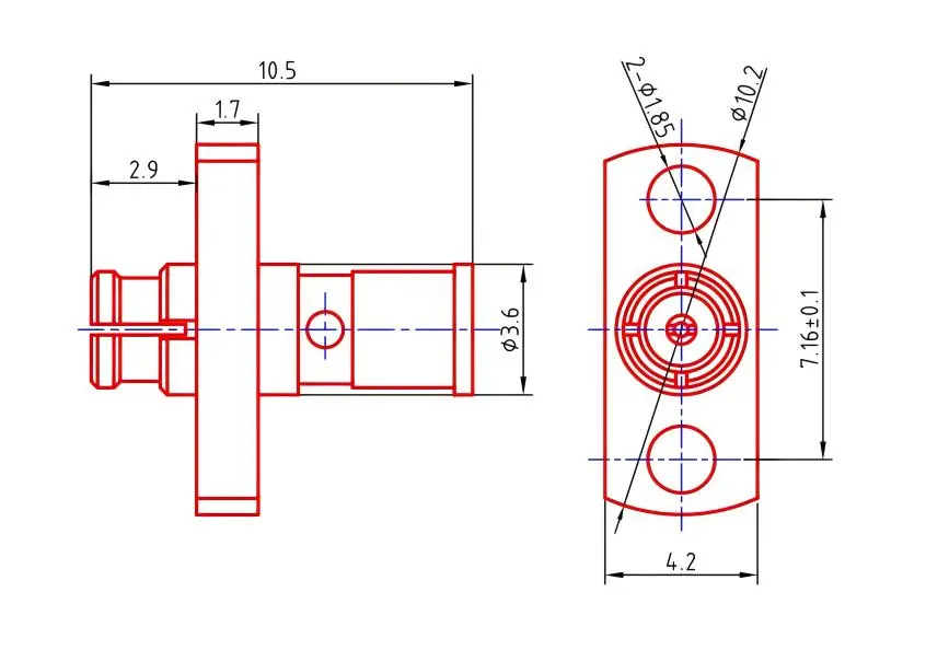
Partner with Chuangyu for Precision GPO RF Connector Solutions
Selecting the right GPO RF connector provider directly impacts your production efficiency and long-term system stability. Shaanxi Chuangyu Electronic Technology Co., Ltd. specializes in precision millimeter-wave communication solutions extending to 110GHz, backed by nearly two decades of engineering experience in RF component manufacturing. Our GPO-KFB2 and compatible assemblies face thorough quality testing linked with MIL-STD-202 standards, guaranteeing consistent VSWR performance and mechanical durability across 500+ mating cycles. As an established RF connector manufacturer with 1,000㎡ of advanced production capacity in Xi'an, we provide customized configurations, comprehensive datasheet support, and rapid response to bulk procurement inquiries. Contact our expert team at chuangyuwz01@cymicrowave.com to discuss your application needs, request sample evaluation units, or receive cheap quotes for large orders. Visit cymicrowave.com to discover our full range of high-frequency interconnect solutions designed for demanding telecommunications, aerospace, and medical uses.
References
1. Johnson, M. R. (2021). High-Frequency Connector Installation: Best Practices for Millimeter-Wave Systems. Boston: RF Engineering Press.
2. Chen, L., & Patel, S. (2020). "Thermal Management in Miniature RF Connector Assemblies." IEEE Transactions on Components, Packaging and Manufacturing Technology, 10(4), 612-625.
3. Military Standard MIL-STD-202G. (2014). Test Methods for Electronic and Electrical Component Parts. U.S. Department of Defense.
4. Rodriguez, A. J. (2022). PCB Design for RF and Microwave Applications: A Practical Guide. Hoboken: Wiley-IEEE Press.
5. International Organization for Standardization. (2018). ISO 9001:2015 Quality Management Systems—Requirements. Geneva: ISO Publications.
6. Williams, T. E., & Zhang, Q. (2023). "Signal Integrity Analysis of Subminiature Push-On Connectors in 5G Infrastructure." Journal of Electronic Packaging, 145(1), 011008-1-011008-9.
