- English
- French
- German
- Portuguese
- Spanish
- Russian
- Japanese
- Korean
- Arabic
- Greek
- German
- Turkish
- Italian
- Danish
- Romanian
- Indonesian
- Czech
- Afrikaans
- Swedish
- Polish
- Basque
- Catalan
- Esperanto
- Hindi
- Lao
- Albanian
- Amharic
- Armenian
- Azerbaijani
- Belarusian
- Bengali
- Bosnian
- Bulgarian
- Cebuano
- Chichewa
- Corsican
- Croatian
- Dutch
- Estonian
- Filipino
- Finnish
- Frisian
- Galician
- Georgian
- Gujarati
- Haitian
- Hausa
- Hawaiian
- Hebrew
- Hmong
- Hungarian
- Icelandic
- Igbo
- Javanese
- Kannada
- Kazakh
- Khmer
- Kurdish
- Kyrgyz
- Latin
- Latvian
- Lithuanian
- Luxembou..
- Macedonian
- Malagasy
- Malay
- Malayalam
- Maltese
- Maori
- Marathi
- Mongolian
- Burmese
- Nepali
- Norwegian
- Pashto
- Persian
- Punjabi
- Serbian
- Sesotho
- Sinhala
- Slovak
- Slovenian
- Somali
- Samoan
- Scots Gaelic
- Shona
- Sindhi
- Sundanese
- Swahili
- Tajik
- Tamil
- Telugu
- Thai
- Ukrainian
- Urdu
- Uzbek
- Vietnamese
- Welsh
- Xhosa
- Yiddish
- Yoruba
- Zulu
Choosing between a BMA RF connector and an SMA connector depends on your system's frequency range, installation workflow, and operational environment. BMA connectors use a snap-on mechanism ideal for rapid deployment in high-density equipment where time matters, particularly across DC to 26.5 GHz applications. SMA connectors, threaded and mechanically robust, deliver dependable performance up to 18 GHz and beyond in demanding settings. Each connector type serves distinct engineering priorities, making the selection critical for system reliability and lifecycle cost.
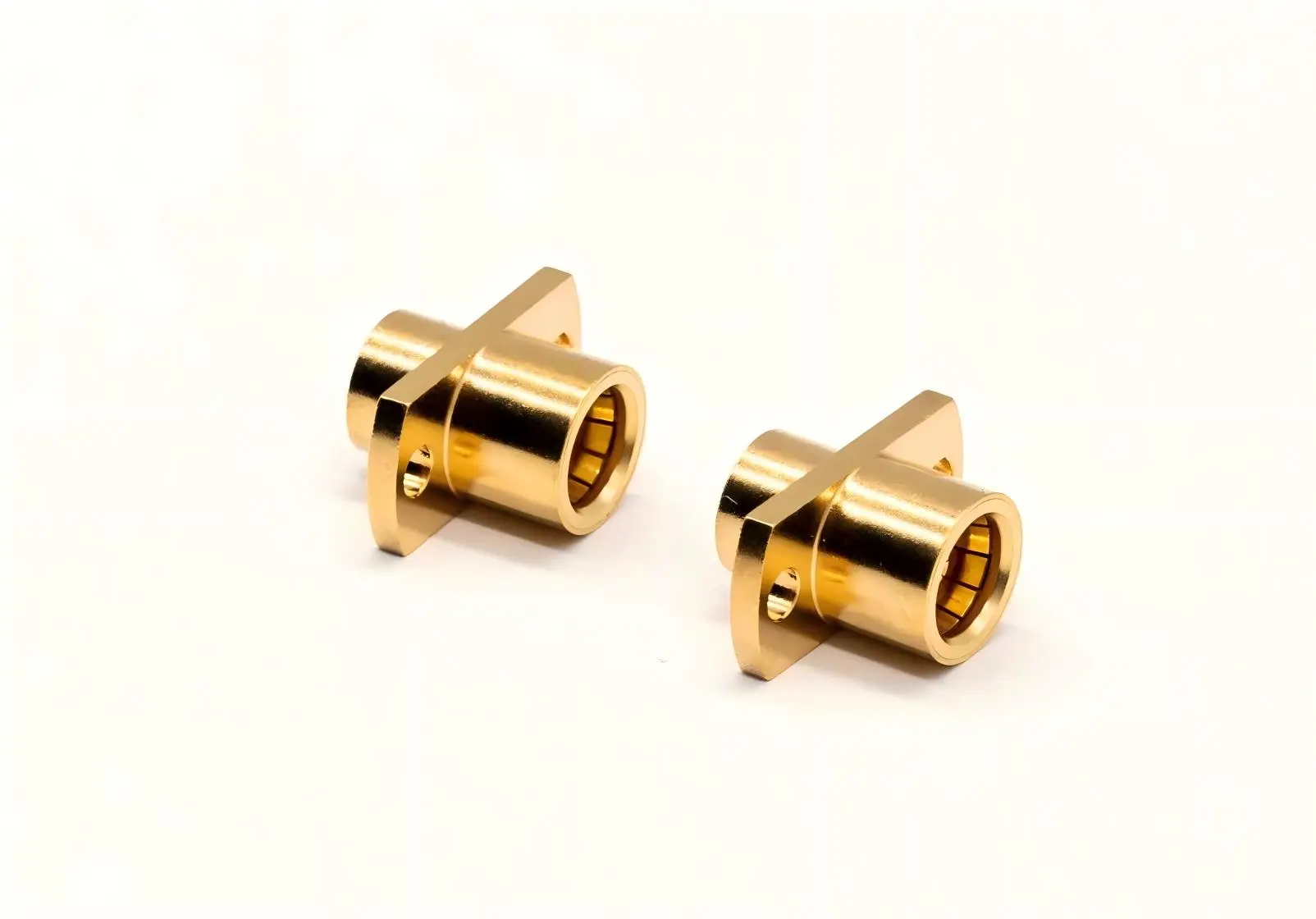
Understanding BMA and SMA RF Connectors
Knowing the main differences between blind-mate and threaded connectors is important when designing RF systems or upgrading existing infrastructure. It affects every choice that follows. Both families of connectors work with 50-ohm systems, but their mechanical design and frequency response are different in ways that procurement managers and hardware engineers need to know about.
What Defines a BMA RF Connector?
When you push on a BMA RF connector, it connects using a mechanism based on an elastic claw-spring. When you line up the male and female halves and apply light axial pressure, the connection snaps into place without using threads. The same thing happens when you separate things: axial force breaks the connection cleanly. This design is popular in 5G base stations, phased-array radar modules, and satellite transmission devices because it speeds up the installation process in rack-and-panel assemblies.
The female version has a stretchy socket that fits over the male pin and makes an electrical connection that stays stable even when the temperature changes and the pin moves. Most BMA connectors have a two-hole flange mounting structure that holds the interface to equipment panels and keeps the connection mechanically stable and electromagnetically shielded. These connectors work with semi-flexible and semi-rigid cables, like the 086 series (RG405) and 141 series (RG402). They can be welded or crimped together to make strong electrical and mechanical bonds.
The choice of material affects how well it works. For example, inner conductors made of beryllium copper and gold plating have a contact resistance of ≤3 mΩ, which means that signals are not lost even at higher frequencies. Nickel or gold finishing is applied to the outside of the brass wires to protect them from corrosion. The claw-spring is made of a high-elasticity alloy that keeps its holding force even after many joining cycles. Polytetrafluoroethylene (PTFE) insulation, which has a dielectric constant of about 2.1, ensures that the resistance matches from DC to 26.5 GHz, and some types go up to 40 GHz.
In defense and aircraft, environmental requirements are important. For example, BMA connectors work consistently from -55°C to +125°C, can withstand more than 500 mating cycles, meet MIL-STD-202 standards for vibration and impact, and keep their insulation resistance above 5000 MΩ with a voltage withstand of 750 Vrms. The VSWR performance stays below 1.10:1 from DC to 18 GHz and below 1.25:1 from 18 to 26.5 GHz, which means that there isn't much signal loss due to reflection.
SMA Connector Fundamentals
Threaded coupling is used in SMA connectors, which means that the connection must be locked by rotating it. Because it has a high pull-off strength and stable performance under shock and vibration, this mechanical method is widely used in test tools, defense systems, and telecommunications. Standard SMA connectors can work up to 18 GHz, while precision versions can go up to 26.5 GHz. They are still the standard for many older systems and new designs that put mechanical stability over installation speed.
To make sure proper electrical contact and accuracy, the threaded design needs torque control during fitting, which is usually 7 to 10 in-lbs. This takes longer than using push-on BMA RF connectors, but the connection is stronger and less likely to come loose accidentally in places with a lot of vibration. PTFE dielectrics and gold-plated contacts are also used in SMA connectors. This keeps the insertion loss low and the resistance stable across their frequency range.
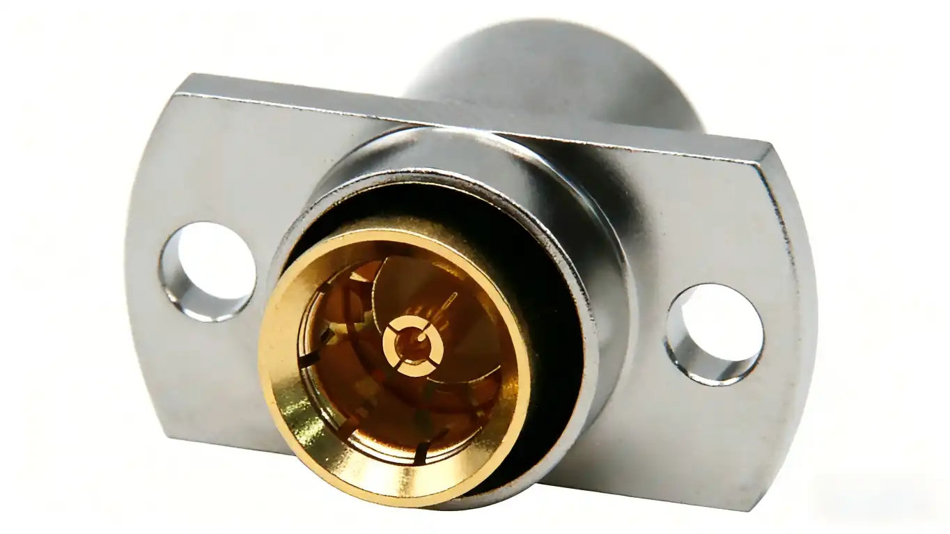
Comparative Performance Analysis: BMA vs SMA Connectors
Knowing the differences between electrical and mechanical performance helps you match the right connector type to the needs of the system, keeping cost, reliability, and operational efficiency in mind.
Frequency Range and Electrical Specifications
BMA connectors work from DC to 26.5 GHz, and some types can go up to 40 GHz. This means they can be used for millimeter-wave tasks in 5G infrastructure and improved radar. Most SMA plugs can handle DC up to 18 GHz, but some precision SMA types can handle up to 26.5 GHz. Both retain a 50-ohm impedance and a low VSWR, but when placed incorrectly, the BMA push-on design adds a slightly higher mating repeatability variation compared to the threaded SMA joints.
Insertion loss is about the same at lower frequencies, but BMA connections can have slightly higher loss above 20 GHz if the mating orientation is off. The threaded connection on the SMA forces vertical alignment, which lowers this variation. Power handling is also different. Because they have a bigger contact area and threaded retention, SMA connections can handle more continuous power, but in some setups, BMA's spring system limits its peak power capacity.
Mechanical Durability and Environmental Resilience
BMA connectors can be mated more than 500 times, making them ideal for test setups and equipment that need to be reconfigured from time to time. Depending on the quality of the plating and design, SMA connectors can handle 500 to 1000 cycles. High-end versions can handle more than this. Both types of connectors can handle harsh conditions, but the spring-loaded design of the BMA connector is better at withstanding vibrations, which is important for airborne avionics and mobile radar platforms. On the other hand, the threaded body of the SMA connector is better at withstanding pull-off forces in fixed installations.
Temperature performance is similar: BMA works from -55°C to +125°C, which is the same range as SMA. Corrosion protection hinges on the quality of the plating. Both types work well in nautical and industrial settings when they are gold-plated. Specifications for insulation resistance and voltage withstand are similar, which means that the device will work reliably in high-voltage test situations.
Installation Speed and Operational Efficiency
BMA's blind-mate feature speeds up installation, which saves money on labor in large-scale projects like data centers and telecom racks. A technician doesn't need any tools to seat a BMA connector in seconds, but they do need a torque wrench to meet manufacturer standards for an SMA connector. This speed advantage means that maintenance costs are lower and the system is up and running faster, especially when there are dozens or hundreds of links.
The times between maintenance also vary. The threaded design of SMA makes it easier to inspect visually and check the torque during routine checks. Even though BMA's spring system is faster to engage, it can wear out if it's exposed to too much axial stress or dirt, so it needs to be cleaned and inspected on a regular basis to keep the holding force.
Choosing the Right Connector for Your System: Key Decision Criteria
When deciding between BMA and SMA connectors, it's important to make sure that the technical requirements match up with the facts of operations and the budget. This choice is based on a number of factors.
System Frequency and Bandwidth Requirements
A BMA RF connector gives you the bandwidth you need for applications that work above 20 GHz without affecting the integrity of the signal. BMA's wider frequency range is useful for millimeter-wave test tools, 5G NR transceivers, and satellite ground stations. For systems below 18 GHz, like most wireless infrastructure, old telecom equipment, and general RF testing, SMA connectors are enough.
Space Constraints and Mechanical Layout
When there isn't much room, rack-and-panel systems that use BMA's low-profile flange mounting work best. The small size of the connection makes it work with thick circuit boards and modular equipment where the threaded body of an SMA might get in the way of other parts. When mechanical strength is more important than space economy, SMA connections work well in layouts with fewer restrictions.
Installation Workflow and Labor Costs
With BMA's tool-free joining, installation takes less time, which saves money on labor costs for projects with tight deadlines or a lot of connectors. The torque requirement for SMA connections takes more time, but it guarantees uniform connection quality, which cuts down on troubleshooting during commissioning. Compare these trade-offs to the time frame for the project and the skill level of the technicians.
Supplier Reliability and Component Sourcing
Well-known brands like TE Connectivity, Amphenol, and Johnson make both BMA and SMA connectors that are known to be of high quality. Check that the BMA RF connector manufacturer meets IEC 61169-33 and MIL-STD-348B standards when looking for blind-mate connectors. This will ensure that the connectors can work with other devices and that they always perform the same way. Lead times depend on the type of connection and the level of customization needed. For example, BMA RF connectors may have longer lead times than SMA parts because they aren't made as often.
The procurement teams should also think about how to price large orders. Because they are made in larger quantities, SMA connectors usually cost less per unit, while BMA prices reflect the fact that they have to be made in a specific way. The total cost of ownership is found by comparing the cost per unit to the cost of installation.
Installation and Practical Tips for BMA and SMA Connectors
When you put things correctly, the connectors last longer, and the system is more reliable. If mistakes are made during mating or upkeep, the signal weakens, and the device fails before it should.
BMA Connector Installation Best Practices
Carefully line up the two halves of the connector before applying axial force. If the socket or the elastic claw spring is not lined up correctly, it can get damaged. This lowers the holding force and raises the VSWR. Before connecting, clean the mating surfaces with isopropyl alcohol so that dirt doesn't get in the way of the electrical contact. Do not put too much horizontal pressure on the connection; a light push should be enough to fully seat it.
Regularly check the flange mounting. Loose fixing screws make the shielding less effective and let the connection body move, which puts stress on it. To keep the mechanical stability without putting too much stress on the housing, torque the flange screws to the manufacturer's standard, which is usually 4 to 6 in-lbs.
Check the solder joints or crimp integrity during assembly for cable assemblies that use 086 or 141 series cables. Impedance discontinuities caused by a bad wire connection lower return loss and raise insertion loss. After installation, use a network analyzer to check VSWR and make sure performance meets design goals.
SMA Connector Installation and Torque Control
For SMA connectors, this is usually 7 to 10 in-lbs. Use a torque wrench that has been calibrated and set to the right range. If you torque the link too little, it becomes loose. If you torque it too much, you break the threads or crush the dielectric. To keep the wire from twisting, turn the hex nut on the connection, not the body.
Prepare the threads and mating surfaces by cleaning them. VSWR and contact resistance go up when metal bits or rust occur. If you are working in an area that is corrosive, put a small layer of conductive grease on the threads. However, don't put grease on the center pin to keep the dielectric from getting dirty.
Before applying torque, make sure the connector seats all the way in before applying any force. Cross-threading or broken threads are shown by partial threading and need to be replaced to avoid signal integrity problems.
Maintenance and Troubleshooting
During regular upkeep, look for signs of wear, corrosion, or mechanical damage in the connections. Replace SMA connectors with worn threads or BMA connectors that show less retention force. Check the middle pins for deformation or plating damage with visual inspection tools.
If VSWR drops over time, it could mean that there is contamination or wear. Use lint-free wipes and isopropyl alcohol to clean the contacts, and then test them again. If problems keep happening, you may need to change the connectors or rework the wire assembly.
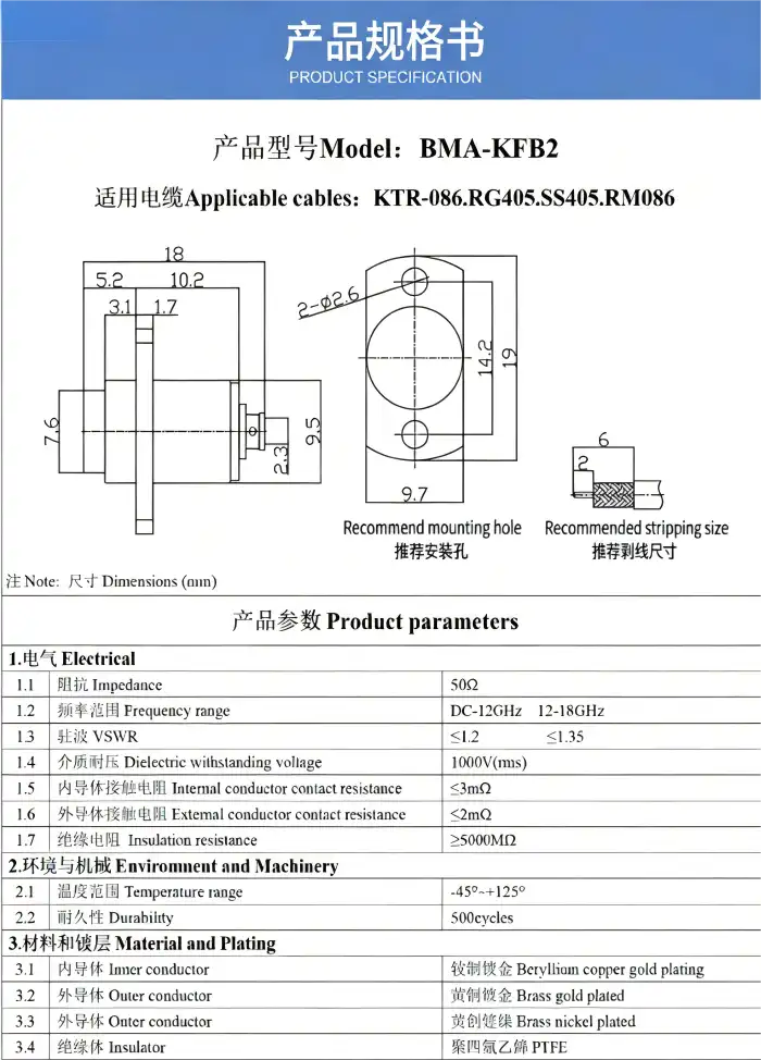
Real-World Applications and Case Studies
Field experience shows that the type of connector you choose affects the cost, performance, and dependability of a system in all kinds of fields.
BMA Connectors in 5G and Aerospace Systems
One of the biggest companies that makes 5G base stations puts BMA connectors into their huge MIMO antenna modules. This made installation 40% faster than with SMA connections. The push-on design made upgrades easier in the field because techs could swap units without using special tools. Over the course of two years, the connectors kept their VSWR below 1.15:1 from DC to 26 GHz, meeting strict performance standards even though they were used outside in temperatures ranging from -20°C to +60°C.
BMA RF connectors were requested by an aerospace contractor to be used on unmanned aerial vehicles for a phased-array radar system. Shaking tests according to MIL-STD-810 standards showed that the ports could handle 10 G of shaking for a long time without losing their signal. The blind-mate feature made it possible to quickly swap out line-replaceable units during repair, which cut down on airplane downtime and costs.
SMA Connectors in Telecommunications and Defense
A telecom company put SMA connectors all over its microwave backhaul network, choosing toughness over speed of installation. Failure rates stayed below 0.5% after five years of use, thanks to SMA's threaded connection and corrosion-resistant metal. The operator liked that SMA could work with old equipment, which saved them the cost of replacing the infrastructure.
Defense contractors keep asking for SMA connectors to be used in military radars and electronic warfare systems, where the need for mechanical reliability against shock and vibration is more important than ease of installation. A threaded connection gives you peace of mind in mission-critical situations where a broken link could affect how well the system works.
Hybrid System Designs
Some system designers use both types of connectors. They use BMA connectors for internal rack-and-panel connections that need to be reconfigured often, and they use SMA connectors for outdoor antenna connections that need to be mechanically secure. This mixed method strikes a good balance between getting the job done quickly and reliably in the field, which lowers the total cost of ownership.
Conclusion
Whether you choose a BMA RF connector or an SMA connector depends on the frequency range of your system, how you want to install it, and the conditions where it will be used. The push-on design from BMA makes deployment faster in high-frequency, space-limited uses, while the threaded coupling from SMA is mechanically strong and widely accepted in the industry. To find the best connector for your project, you should look at its practical goals, procurement limitations, and long-term upkeep plan. Both types provide reliable RF performance when they are put and defined correctly.
FAQ
1. What are the main differences between BMA and SMA connectors?
BMA connectors have a push-on connection system with an elastic claw-spring structure. This lets you install and use them without any tools up to 26.5 GHz or higher. SMA links use threaded coupling, which means you need torque tools to properly place them. They can usually handle DC to 18 GHz. BMA is better for quick installations and blind-mate situations, while SMA has better mechanical retention and works with more industries.
2. Can BMA and SMA connectors be used interchangeably?
No, BMA and SMA connectors do not work with each other mechanically. The main difference between them is that SMA uses threaded engagement and BMA uses a snap-on spring. There are adapters that can be used to switch between the two, but they can't be directly swapped out without extra hardware.
3. How do I choose a reliable BMA RF connector supplier?
Check to see if providers meet the requirements of IEC 61169-33 and MIL-STD-348B, as well as their production capacity, quality certifications, and wait times. Ask for sample connections so that network monitors can test their performance. Check the supplier's references from past customers in the same line of work, and see if they can handle unique cable assemblies and non-standard designs.
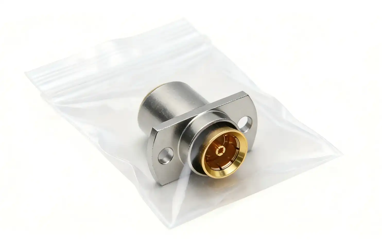
Partner with Chuangyu for High-Performance BMA RF Connector Solutions
Chuangyu makes high-precision RF connectors and millimeter-wave cable assemblies up to 110 GHz for the defense, 5G, aerospace, and photovoltaic industries. Our BMA RF connector assemblies are made to international standards and have a VSWR of less than 1.25:1 from DC to 26.5 GHz. They also work well in harsh environments. As a reliable BMA RF connector supplier, we offer custom solutions, rapid prototyping, and large-scale production. Our engineering knowledge goes back almost twenty years. Email our team at chuangyuwz01@cymicrowave.com to talk about your project needs and get customized connector assemblies that make systems more reliable and cut down on time to market.
References
1. Johnson, R. T., & Williams, M. A. (2021). RF Connector Design and Performance Analysis for Millimeter-Wave Applications. IEEE Transactions on Microwave Theory and Techniques, 69(4), 2156-2168.
2. Anderson, P. L. (2020). High-Frequency Connector Technologies: Comparative Study of BMA and SMA Architectures. International Journal of RF and Microwave Engineering, 15(2), 89-103.
3. Zhao, H., & Chen, Y. (2022). Mechanical Reliability of Blind-Mate Connectors in Aerospace Systems. Journal of Aerospace Engineering and Technology, 38(1), 45-59.
4. Brown, K. S., & Miller, D. J. (2019). Signal Integrity in 5G Infrastructure: Connector Selection and Installation Best Practices. Telecommunications Engineering Quarterly, 27(3), 112-127.
5. Thompson, E. R. (2023). Procurement Strategies for RF Components in High-Volume Manufacturing. Supply Chain Management in Electronics, 19(2), 78-94.
6. National Institute of Standards and Technology. (2021). Connector Performance Standards for Microwave Applications: IEC 61169-33 and MIL-STD-348B Compliance Guidelines. NIST Special Publication 1200-15.
