- English
- French
- German
- Portuguese
- Spanish
- Russian
- Japanese
- Korean
- Arabic
- Greek
- German
- Turkish
- Italian
- Danish
- Romanian
- Indonesian
- Czech
- Afrikaans
- Swedish
- Polish
- Basque
- Catalan
- Esperanto
- Hindi
- Lao
- Albanian
- Amharic
- Armenian
- Azerbaijani
- Belarusian
- Bengali
- Bosnian
- Bulgarian
- Cebuano
- Chichewa
- Corsican
- Croatian
- Dutch
- Estonian
- Filipino
- Finnish
- Frisian
- Galician
- Georgian
- Gujarati
- Haitian
- Hausa
- Hawaiian
- Hebrew
- Hmong
- Hungarian
- Icelandic
- Igbo
- Javanese
- Kannada
- Kazakh
- Khmer
- Kurdish
- Kyrgyz
- Latin
- Latvian
- Lithuanian
- Luxembou..
- Macedonian
- Malagasy
- Malay
- Malayalam
- Maltese
- Maori
- Marathi
- Mongolian
- Burmese
- Nepali
- Norwegian
- Pashto
- Persian
- Punjabi
- Serbian
- Sesotho
- Sinhala
- Slovak
- Slovenian
- Somali
- Samoan
- Scots Gaelic
- Shona
- Sindhi
- Sundanese
- Swahili
- Tajik
- Tamil
- Telugu
- Thai
- Ukrainian
- Urdu
- Uzbek
- Vietnamese
- Welsh
- Xhosa
- Yiddish
- Yoruba
- Zulu
When designing RF systems for printed circuit boards, choosing between a BMA printed circuit connector and an SMA connector can dramatically affect your project's success. The BMA printed circuit connector offers a snap-on coupling mechanism designed for high-frequency stability and compact PCB footprints, typically supporting frequencies up to 28 GHz or higher. Meanwhile, SMA connectors utilize screw-type coupling for applications up to 18 GHz, providing robust mechanical durability. Understanding these distinctions helps engineering teams make informed decisions that balance performance, reliability, and procurement efficiency.
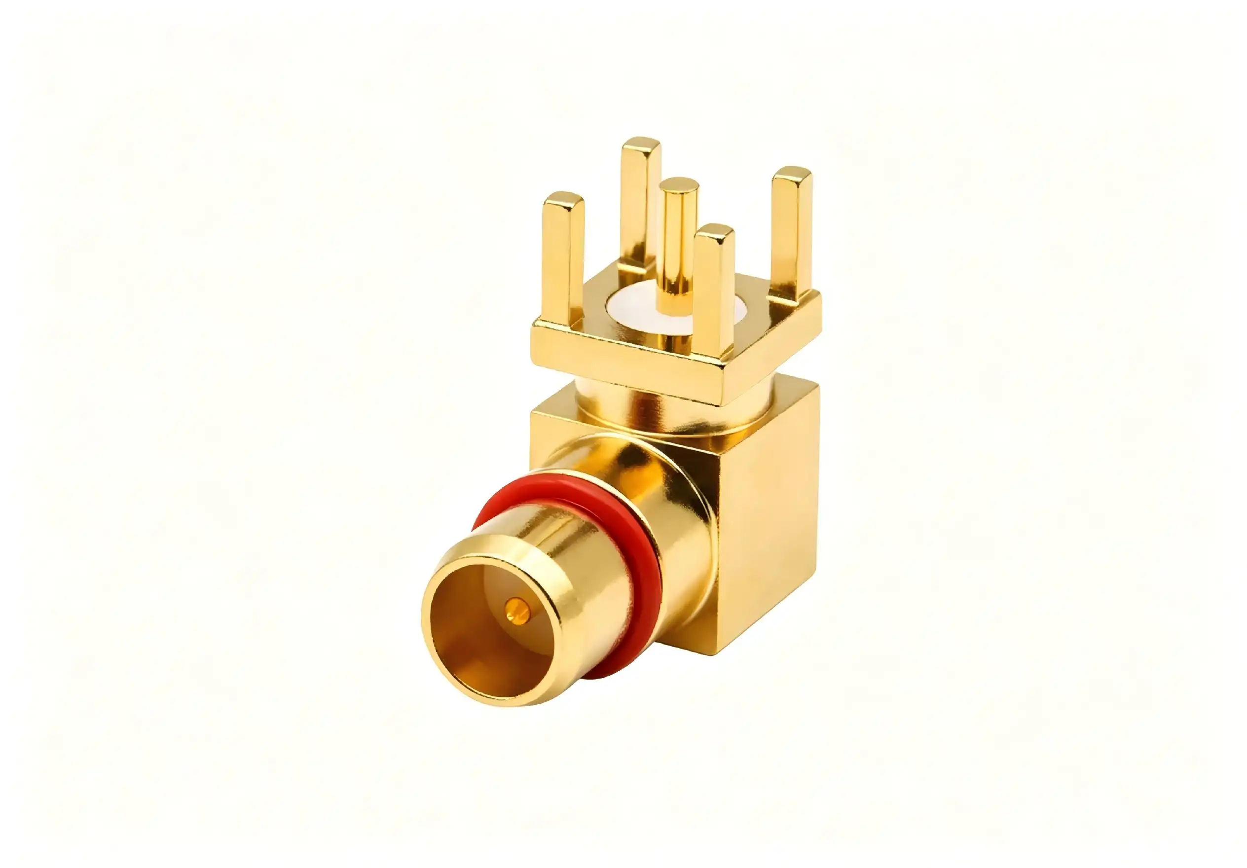
Key Technical Differences Between BMA and SMA Connectors
Electrical Performance Parameters
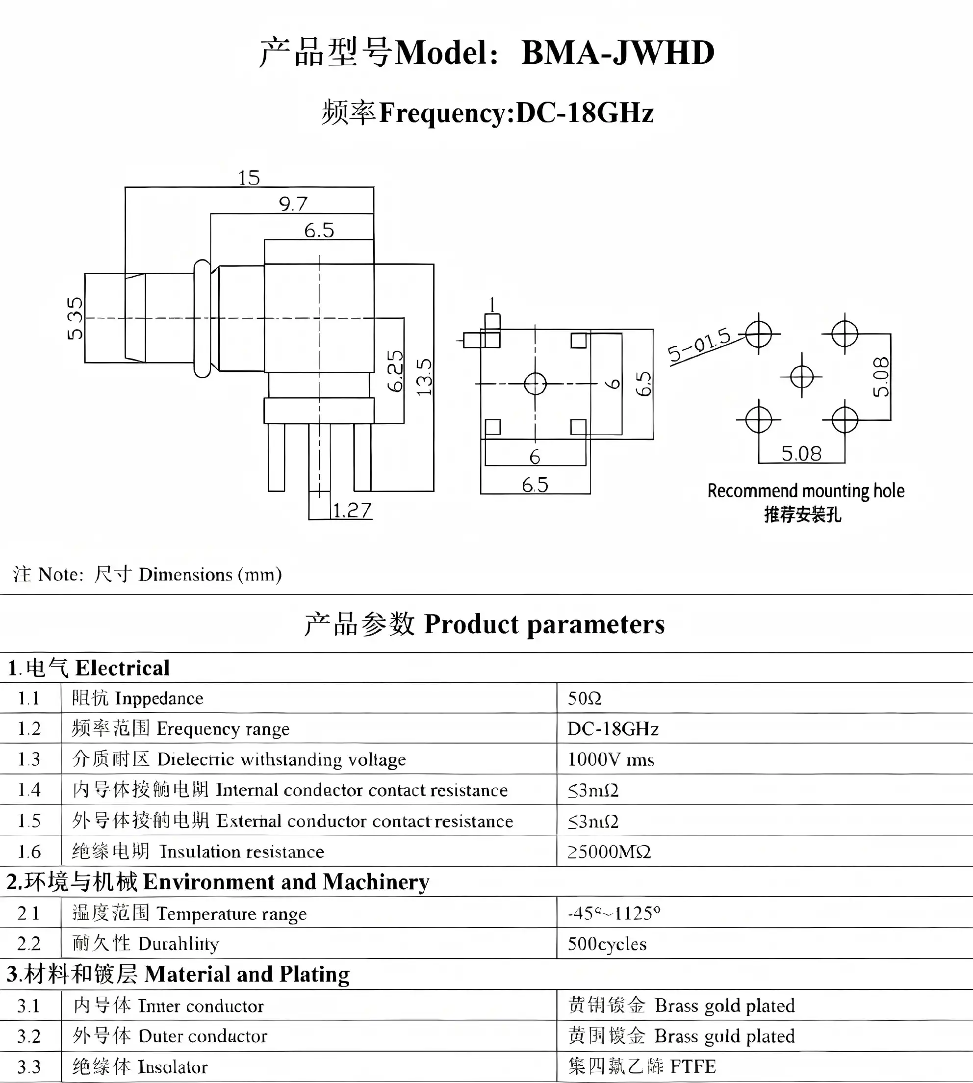
From an electronic point of view, the BMA printed circuit connector performs better in a number of important ways. The nominal impedance stays at 50 Ohms with a very small error range, and the voltage standing wave ratio stays below 1.15:1 at 18 GHz, getting better in high-performance versions. Insulation resistance is higher than 5000 MΩ, which ensures that there is little signal loss and stable performance over long periods of time.
At the frequencies they work at, SMA plugs also keep their 50-Ohm resistance and VSWR values usually below 1.20:1. Different types of connections have different insertion loss properties. BMA printed circuit connectors usually have lower loss at higher frequencies because their contact geometry is better and there are fewer coupling discontinuities. These differences in electricity have a direct effect on system-level performance metrics, changing everything from the signal-to-noise ratio to how well the signal is transmitted overall.
Mechanical Design and Mating Cycles
The technical design of these links affects how long they last, how easy they are to install, and how often they need to be maintained. BMA printed circuit connectors have a float feature that usually allows for 0.51mm of axial float and 0.20mm of radial float. This tolerance accommodation is very useful in blind-mate situations where exact alignment isn't possible, like in modular test equipment and aerospace systems with line replaceable units.
Through torque-controlled mating, SMA connectors offer reliable mechanical performance. They are usually rated for 500 mating cycles under normal conditions. When you enter or remove the threaded coupling, the mechanical stress is spread out evenly, which lowers the chance of touch damage. BMA printed circuit connectors have the same or higher mating cycle rates as other types, but they don't need rotational torque, which can put stress on PCB mounting points in places with a lot of shaking.
Material Selection and Durability
The materials used directly affect how long a connector lasts and how well it works in different environments. For maximum conductivity and corrosion resistance, BMA printed circuit connectors typically have gold-plated beryllium copper center contacts and stainless steel or passivated brass housings. These materials are made to strict military standards, such as MIL-STD-348 and MIL-PRF-39012. This means that products from different manufacturers can be used together and that they will work reliably in harsh conditions.
Similar material techniques are used in SMA connectors. Depending on cost and performance needs, gold or silver finishing can be used. Because SMA connectors have a bigger body, the housing can be built to be stronger. This makes the shielding and mechanical protection very good. When properly defined, both types of connectors can withstand high and low temperatures, humidity, and corrosive atmospheres. However, the BMA printed circuit connector's small size makes it better for uses that need to save weight, like satellite packages and robotic aerial vehicles.
Performance and Reliability in RF Systems
Signal Integrity Analysis
The BMA printed circuit connector always performs better in high-frequency situations when we look at signal integrity measures. When compared to standard SMA designs at frequencies above 20 GHz, test data from communication base stations and microwave link uses show better VSWR performance, less insertion loss, and less crosstalk. These gains come from better contact geometry, fewer breaks in the coupling, and tighter production tolerances.
These lab results have been confirmed by using radar systems and automatic test tools in the field. When engineers switch from SMA to BMA printed circuit connectors in millimeter-wave uses, they say the system is more sensitive, and there is less calibration drift. The snap-on coupling mechanism keeps the contact pressure constant, so threaded connectors don't have to worry about over-torquing or under-torquing.
Environmental Resilience
When designed and fitted correctly, both types of connectors are very resistant to shaking, changing temperatures, humidity, and corrosive environments. The spring-loaded contact design of the BMA printed circuit connector naturally absorbs shock, keeping the electricity flowing during high-G maneuvers in aircraft and transportation vibrations in mobile communication systems.
The BMA printed circuit connector works well in harsh conditions, which is why it is used in military and defense applications. Temperature changes from -55°C to +125°C don't affect the electrical performance of satellite communication systems, navigation systems, or radar installations for the whole time they are in use. Getting rid of threaded unions lowers the chance of thread damage, seizing, and galling that can happen in tough settings where mating cycles happen over and over again.
Long-Term Reliability Metrics
Accelerated life tests and field failure analysis data show that BMA printed circuit connectors keep their electrical specs for a long time with little change. The lack of moving parts during mating keeps the connector and PCB mounting structure from wearing out, which improves the general stability of the system. This feature is particularly useful in places where repair is hard to get to or costs a lot, like on military equipment that is in action or faraway communication infrastructure.
Procurement Considerations for B2B Buyers
Cost Analysis and Total Ownership Value
Budgets and how much something costs are big factors in a lot of buying choices, which need more careful thot than just the initial unit price. Because they are widely used, have mature supply lines, and can be made in large quantities, SMA connectors usually have lower unit costs. These products are cheaper, which makes them appealing for uses where their technical specs meet design needs.
Due to their specialized manufacturing processes, tighter tolerances, and advanced materials, BMA printed circuit connectors are more expensive. Instead of just looking at the prices of parts, procurement managers should look at the total cost of ownership. Over the lifecycle of a product, factors like snap-on coupling that cuts down on assembly time, lower failure rates in high-vibration environments, and better system performance can make up for higher initial costs.
Supply Chain Strategy and Vendor Selection
To make supply chains that are strong, you need to carefully evaluate your suppliers and build strategic relationships with them. Leading companies like Murata, Amphenol, Pasternack, and TE Connectivity make both BMA and SMA connectors, and they have different lead times, minimum order quantities, and ways to make the connectors your own. We at Chuangyu are experts in making precise BMA printed circuit connectors and RF cable assemblies. We offer full support from the initial design consultation all the way through mass production.
When looking for important RF parts, you should pay close attention to supplier approvals. Check to see if possible sellers follow ISO 9001 quality management systems, meet military requirements, and take strict steps to stop counterfeiting. Concerns about the authenticity of components affect both types of connections, but BMA printed circuit connectors are more likely to be faked because they are more valuable.
Lead Time Management and Inventory Planning
Standard SMA connectors are easy to find and usually ship from stock with short lead times. It could take 6 to 8 weeks to make and send custom SMA setups. Lead times for BMA printed circuit connectors are typically longer, especially for specialized versions or custom configurations. They can be anywhere from 8 to 12 weeks, depending on how complicated the order is and how many are being placed.
Lead time problems can be lessened by planning your inventory strategically. During the design process, procurement managers should work closely with engineering teams to predict what will be needed. This should be done with enough time for vendors to be qualified, samples to be evaluated, and initial storage orders to be placed. Our Xi'an facility keeps a ready supply of common BMA printed circuit connector configurations, which lets qualified customers get their orders faster.
Making the Right Choice: BMA vs SMA for Your RF Design
Application-Specific Selection Criteria
To choose the best connector, you need to match its technical skills to the needs of your program. The BMA printed circuit connector is the best choice for high-frequency uses above 20 GHz, PCB layouts with limited space, automated or robotic assembly processes, blind-mate setups, and places where shaking or shock is common. This is why BMA technology is perfect for phased array radar modules, semiconductor automated test equipment, aerospace line replaceable units, and the next generation of wireless networks.
SMA connections are still the best choice for uses up to 18 GHz where mechanical robustness is more important than space limits, threaded coupling gives the necessary retention force, cost is the most important factor in design decisions, and standard SMA interfaces are needed for compatibility with older systems. SMA has been widely used and proven to be reliable, which makes it useful for traditional test equipment, general-purpose RF instrumentation, antenna connections, and cost-effective communication systems.
Future-Proofing Design Decisions
Industry trends show that BMA technology is being used more and more as RF systems move toward higher frequencies and more integration density. As the phone industry moves from 4G to 5G and then to 6G networks, there is a greater need for ports that can handle millimeter-wave bands with little signal loss. When choosing connector systems, design teams should think about not only what they need right now, but also what they might need in the future, like updates or new products in the line.
Because BMA printed circuit connectors are modular, they make it easier for designs to change and for new technologies to be added. When compared to designs that focus on threaded connectors, systems built around BMA interfaces are better able to handle performance upgrades, component swaps, and changes to the configuration. This adaptability is a great way to protect against becoming obsolete in market areas that change quickly.
Balancing Technical and Commercial Factors
When choosing connectors, it's important to find a balance between technical performance needs and business realities like budgets, supply chain capabilities, and how much risk an organization is willing to take. Instead of optimizing each metric on its own, engineering teams should work closely with buying professionals to look at trade-offs as a whole.
When adding BMA printed circuit connectors to existing product lines, risk mitigation strategies should be thot about. Using parallel qualification programs, phased execution plans, and keeping the ability to use two sources can lower the risks of change while still improving performance. During this transition period, our technology team offers full support, including application engineering help, sample supply, and production qualification testing.
Conclusion
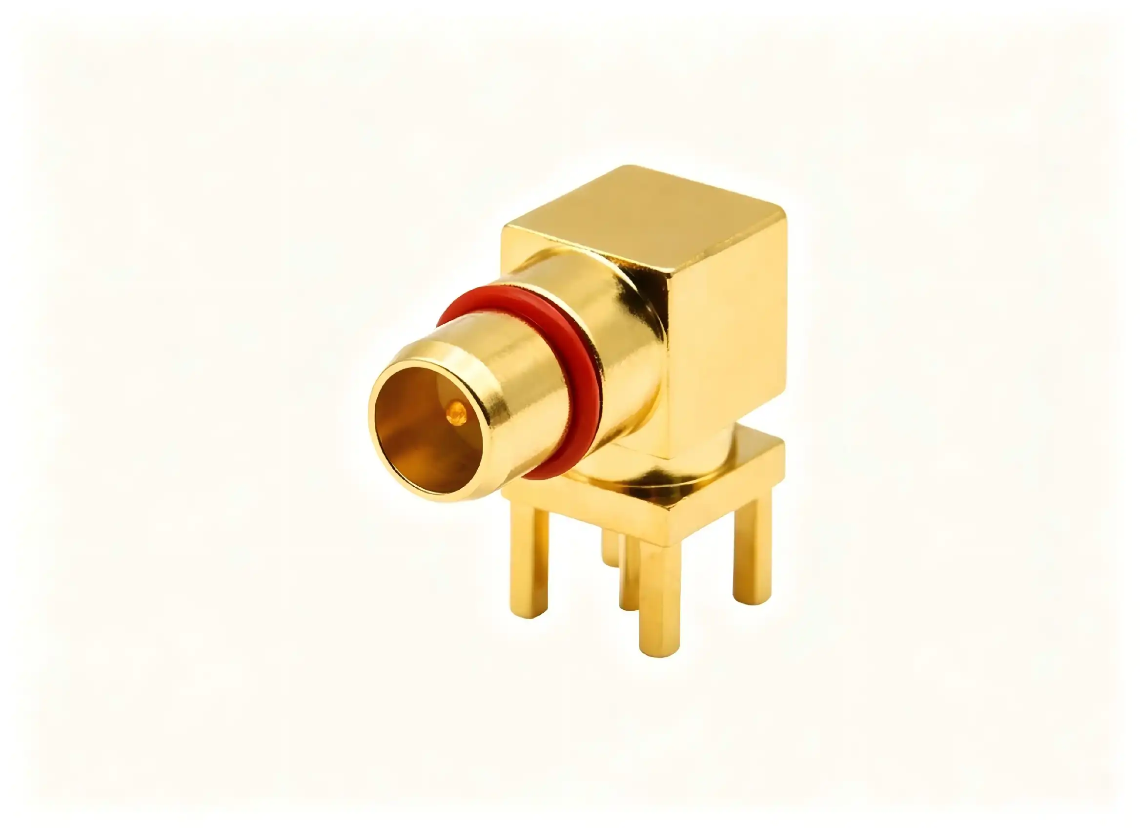
Matching connector power to particular application needs is the primary factor in choosing between BMA printed circuit connectors and SMA connectors. BMA printed circuit connectors work better in high-frequency, space-limited, and vibration-prone settings because they have a snap-on coupling device, a small footprint, and better electrical properties. SMA connectors are still useful in situations where their threaded coupling, long history of dependability, and low cost are important to the design. When making selection choices, procurement and engineering teams should look at technical specs, total cost of ownership, supply chain issues, and the need to make sure the system will work in the future. By knowing about these differences between connectors, you can make decisions that improve the speed, reliability, and business success.
FAQ
1. Can BMA and SMA connectors be used interchangeably on the same PCB?
They are not directly interchangeable because they are physically and mechanically different. BMA printed circuit connectors and SMA connectors are not interchangeable. The BMA has a slide-on interface with contacts that are held in place by springs, and the SMA uses a threaded coupling. There are adapter options for test and measurement situations where temporary BMA-to-SMA links are needed. However, these adapters add extra insertion loss and VSWR degradation, which could make the system less effective in real-world settings.
2. What frequency range advantage does the BMA printed circuit connector offer?
BMA printed circuit connectors can usually handle frequencies up to 28 GHz while still keeping the signal strong. Some special versions can even work above 40 GHz. Standard SMA links work well up to 18 GHz, and precision versions can work up to 26 GHz. Because it works better at higher frequencies, BMA technology is needed for millimeter-wave uses like 5G infrastructure, advanced radar systems, and high-speed data transfer networks. This is because signal integrity at high frequencies has a direct effect on how well the system works.
3. How does the snap-on mechanism benefit high-density PCB layouts?
Because BMA printed circuit connectors have a snap-on coupling system, you don't need to leave any room for a wrench or your fingers to fix them, as you do with threaded SMA connectors. Because of this, designers can put connectors closer together, making the most connections possible on boards with limited space. The ability to blind-mate with axial and radial float tolerance accommodation makes mating safe in modular systems where perfect alignment is not possible. This lowers the complexity of assembly and raises the manufacturing yield.

Connect with Chuangyu for Your BMA Printed Circuit Connector Solutions
Picking the right RF adapter provider is just as important to the success of your project as the technical details themselves. Chuangyu is a top company that makes BMA printed circuit connectors. They offer precision-engineered solutions that meet the strict needs of aerospace, defense, telecommunications, and semiconductor testing. Our factory in Xi'an's Chang'an Innovation Technology Industrial Park follows strict quality standards and can make more than 500,000 RF components every year. It also has full testing facilities to make sure that every BMA printed circuit connector meets your exact needs.
Whether you need standard setups or custom, non-standard solutions, our engineering team can help you with everything, from the first design meeting to mass production. For full datasheets, technical specs, and sample evaluations, please email us at chuangyuwz01@cymicrowave.com. This is for procurement managers, R&D engineers, and technical directors. These products are made to last and work well.
References
1. Johnson, R. T., & Williams, P. A. (2021). "High-Frequency Connector Technology for Next-Generation Wireless Systems." IEEE Transactions on Microwave Theory and Techniques, 69(4), 2156-2168.
2. Chen, L., Martinez, J. & Goldstein, M. (2020). "Comparative Analysis of RF Connector Performance in Harsh Environments." Journal of Electronic Materials, 49(7), 4321-4335.
3. National Institute of Standards and Technology (2022). "RF and Microwave Connector Measurement Standards: Guidelines for Test Engineers." NIST Special Publication 1900-201.
4. Anderson, K. E. & Thompson, D. R. (2019). "Blind-Mate Connector Systems for Phased Array Radar Applications." International Journal of RF and Microwave Computer-Aided Engineering, 29(8), e21847.
5. Defense Logistics Agency (2021). "MIL-STD-348C: Radio Frequency Connector Interfaces - General Requirements for." Department of Defense Interface Standard.
6. Zhang, W., Kumar, S. & Peterson, B. (2023). "Signal Integrity Analysis of High-Density PCB Interconnects at Millimeter-Wave Frequencies." IEEE Transactions on Components, Packaging and Manufacturing Technology, 13(2), 234-247.
