- English
- French
- German
- Portuguese
- Spanish
- Russian
- Japanese
- Korean
- Arabic
- Greek
- German
- Turkish
- Italian
- Danish
- Romanian
- Indonesian
- Czech
- Afrikaans
- Swedish
- Polish
- Basque
- Catalan
- Esperanto
- Hindi
- Lao
- Albanian
- Amharic
- Armenian
- Azerbaijani
- Belarusian
- Bengali
- Bosnian
- Bulgarian
- Cebuano
- Chichewa
- Corsican
- Croatian
- Dutch
- Estonian
- Filipino
- Finnish
- Frisian
- Galician
- Georgian
- Gujarati
- Haitian
- Hausa
- Hawaiian
- Hebrew
- Hmong
- Hungarian
- Icelandic
- Igbo
- Javanese
- Kannada
- Kazakh
- Khmer
- Kurdish
- Kyrgyz
- Latin
- Latvian
- Lithuanian
- Luxembou..
- Macedonian
- Malagasy
- Malay
- Malayalam
- Maltese
- Maori
- Marathi
- Mongolian
- Burmese
- Nepali
- Norwegian
- Pashto
- Persian
- Punjabi
- Serbian
- Sesotho
- Sinhala
- Slovak
- Slovenian
- Somali
- Samoan
- Scots Gaelic
- Shona
- Sindhi
- Sundanese
- Swahili
- Tajik
- Tamil
- Telugu
- Thai
- Ukrainian
- Urdu
- Uzbek
- Vietnamese
- Welsh
- Xhosa
- Yiddish
- Yoruba
- Zulu
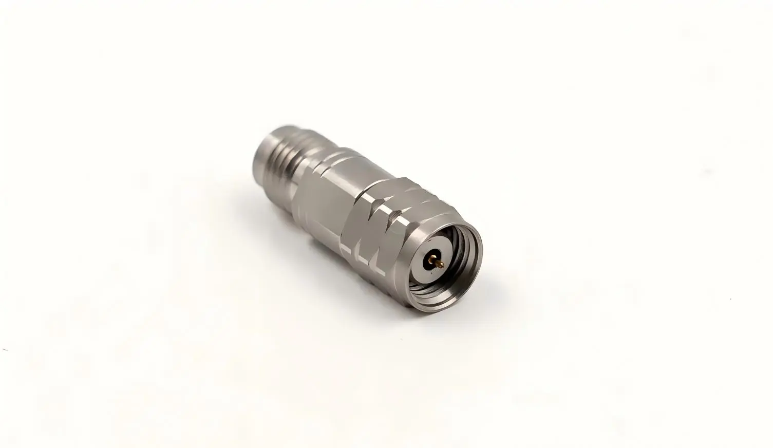
You already understand the importance of each connection in your signal chain, whether you work in millimeter-wave testing, 5G development, or precise RF measurement. One of the parts that silently connects high-frequency systems is a Coaxial adapter 1.85mm plug to 1.85mm jack. This adapter is essential for engineers and procurement managers looking for dependable RF interconnects for demanding test and measurement applications since it allows polarity conversion within the same 1.85mm interface series and operates from DC to 67 GHz with VSWR ≤1.35.
Understanding 1.85mm Coaxial Adapters
Structural Design and Electrical Architecture
The 50Ω characteristic impedance coaxial structure serves as the foundation for the 1.85mm coaxial adapter. For better conductivity and resistance to oxidation, its central conductor is made of beryllium copper that has been gold-plated. Polytetrafluoroethylene (PTFE) was used as the insulating dielectric because of its low dielectric loss at millimeter-wave frequencies. Strong electromagnetic shielding and mechanical integrity are provided by the precision-machined stainless steel outer conductor. Low-loss signal transmission is made possible by this three-layer design over the whole DC to 67 GHz operational range.
Gender Conversion Mechanism
The adapter has a 1.85mm female connection with internal socket geometry on one end and a 1.85mm male connector with an exposed center pin arrangement on the other. Interface polarity discrepancies within the same connector series are resolved by this plug-to-jack configuration without causing further signal loss. At frequencies where even small discontinuities result in detectable reflection, the coaxial adapter 1.85mm plug to 1.85mm jack design preserves signal integrity by maintaining a constant 50Ω impedance during the transition.
With a plug life rated at ≥500 mating cycles and a VSWR standard of ≤1.35 over the whole bandwidth, this adapter is appropriate for both production-line and laboratory applications.
Top Uses of 1.85mm Coaxial Adapters in Industrial Applications
Systems with narrow performance margins are a good fit for high-frequency RF adapters. Beyond 40 GHz, when alternatives like 2.92mm connections start to reveal their limits, the 1.85mm interface performs very well in settings that require exact signal quality. The 1.85mm coaxial adapter provides quantifiable value in the following key application domains:
- Millimeter-wave communication testing: Engineers connect vector network analysers (VNAs) and spectrum analysers to satellite communication assemblies, millimeter-wave radar modules, and 5G base station hardware using a 1.85mm plug-to-jack adaptor. When characterising components working in the 24–67 GHz range, the adaptor guarantees phase-stable, low-loss signal routes.
- Semiconductor RF development: Interface compatibility between probe stations and test equipment is necessary for wafer-level testing of millimeter-wave sensor ICs and 5G RF chipsets. At the device border, a 1.85mm male-to-female adaptor maintains signal integrity while performing the required polarity conversion.
- Aerospace and defence: RF connections with excellent environmental durability are required for military phased array radar systems and electronic warfare equipment. The 1.85mm adapter's stainless steel outer conductor satisfies the strict dependability requirements placed on defense-grade assemblies by withstanding corrosion and mechanical stress.
- Integration of test fixtures: Polarity mismatches between instruments and devices under test are a common problem for system integrators creating automated RF test platforms. By effectively resolving these incompatibilities, the coaxial adapter 1.85mm plug to 1.85mm jack increases the compatibility of the current test infrastructure without requiring modification.
When creating precise RF test chains, OEM manufacturers, R&D labs, and system integrators regularly select 1.85mm adapters, as these examples together demonstrate.
Benefits of Using 1.85mm Coaxial Adapters
The 1.85mm interface has a well-established performance case over alternatives with a larger diameter. The Coaxial adapter 1.85mm plug to 1.85mm jack increases usable bandwidth to 67 GHz while keeping similar insertion loss numbers when compared to 2.4mm connections (certified to 50 GHz) and 2.92mm kinds (rated to 40 GHz). The following are the main benefits that characterise this component:
- Extended frequency coverage: The whole sub-THz millimeter-wave test range, including 5G NR FR2 frequencies and automobile radar bands at the 76–77 GHz border applications, is covered by DC-to-67 GHz operation.
- Low reflection coefficient: VSWR ≤1.35 indicates a return loss of more than 16 dB, which is crucial in cascaded test configurations since less than 2% of the incident signal power reflects at the adapter interface.
- Mechanical durability: After at least 500 mating cycles, gold-plated beryllium copper center pins maintain contact force. In high-throughput test settings, stainless steel outer bodies lessen the need for replacement since they are resistant to environmental corrosion and thread wear.
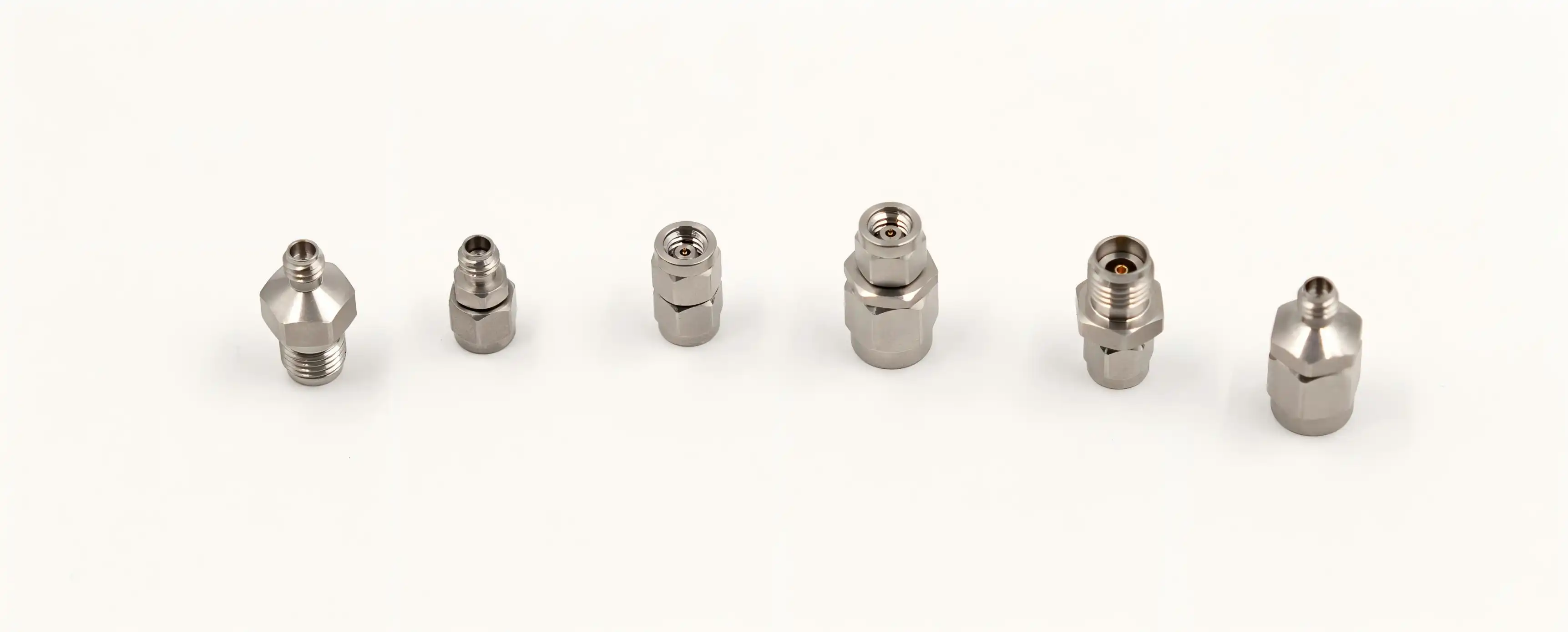
- Wide system compatibility: By integrating with semi-rigid cables, flexible cable assemblies, and panel-mount fixtures within the same interface family, the 1.85 mm male-to-female adapter lowers the number of adapter variations that a procurement team has to keep track of.
Engineers and procurement managers care about these benefits because they immediately result in decreased measurement uncertainty, cheaper long-term component prices, and fewer signal chain disruptions.
How to Choose the Right 1.85mm Coaxial Adapter for Your Needs
Making sure the 1.85mm interface is really required by your system's frequency ceiling is the first step in choosing the right adapter. A 2.92mm adapter can be a more affordable option if your maximum operating frequency remains below 40 GHz. However, the 1.85mm series is the right standard for any application involving 5G mmWave bands, Ka-band radar, or high-resolution VNA measurements over 50 GHz.
Instead of evaluating VSWR at a single frequency point, do it over the whole operating band. Ask vendors for calibrated measurement data rather than simply datasheet figures. The manufacturing accuracy required for reproducible outcomes is shown by suppliers who can provide verifiable performance verification. With over 20 years of experience producing RF connectors, an annual production capacity of 500,000 RF components, and established quality control procedures in line with international standards, Chuangyu produces its 1.85mm coaxial adapters in Xi'an.
Verify lead times against your project plan when making bulk purchases of Coaxial adapter 1.85mm plug to 1.85mm jack, and enquire about unique interface configurations if your assembly calls for non-standard body lengths or thread engagements.
Installation and Troubleshooting Tips for 1.85mm Coaxial Adapters
Pre-Use Inspection
Before connecting any 1.85mm RF adapter, inspect the outer conductor for deformation, verify the gold plating shows no peeling or discoloration, and confirm the center pin or socket carries no oxidation or physical damage. A damaged adapter must be replaced immediately — continuing to use a compromised connector introduces measurement errors and risks damaging the mating port on expensive test instruments.
Installation Procedure
Align the connector interfaces carefully before engagement. Apply torque using a calibrated torque wrench set to ≤0.5 N·m, as specified in the product documentation. Oblique insertion or over-tightening are the two most common causes of center pin damage in millimeter-wave connectors. Operating frequency must stay within the DC–67 GHz rated range, and signal power must not exceed the rated maximum. Conduct testing inside a shielded enclosure to suppress external electromagnetic interference that would otherwise corrupt measurement data.
Maintenance and Storage
Clean connector interfaces using dedicated RF cleaning swabs moistened with anhydrous isopropyl alcohol. Store adapters in sealed, dry enclosures away from corrosive gases, within a temperature range of -10°C to 40°C and relative humidity ≤60% RH. If VSWR rises unexpectedly or signal attenuation increases without an obvious system change, immediately inspect the adapter for wear or misalignment. Never continue testing with a suspected faulty adapter — doing so risks cascading damage to connected equipment.
Conclusion
The Coaxial adapter 1.85mm plug to 1.85mm jack addresses a specific and demanding niche in RF interconnect engineering: reliable, low-loss gender conversion at frequencies up to 67 GHz. Its gold-plated beryllium copper center conductor, PTFE dielectric, and stainless steel outer body create a connector capable of sustaining precision performance through hundreds of mating cycles. Whether you are building 5G test benches, qualifying aerospace RF assemblies, or expanding semiconductor wafer-level test infrastructure, specifying the correct 1.85mm plug to jack adapter is a straightforward decision with measurable performance consequences.
FAQ
What frequency range does a 1.85mm coaxial adapter support?
The 1.85mm coaxial adapter operates from DC to 67 GHz, covering millimeter-wave test bands including 5G NR FR2, Ka-band, and V-band applications. This range exceeds 2.4mm (50 GHz) and 2.92mm (40 GHz) alternatives.
Is a 1.85mm adapter interchangeable with a 2.4mm connector?
The 1.85mm and 2.4mm interfaces are mechanically incompatible and must not be mated directly. Each connector series has distinct outer conductor dimensions and thread engagement specifications. Attempting cross-series mating risks physical damage to both connectors.
What should I verify when sourcing a 1.85mm plug to 1.85mm jack adapter from a supplier?
Request documented VSWR data across the full frequency range, confirm plugging life ratings (≥500 cycles minimum), verify material specifications for the center conductor and outer body, and ask for evidence of quality control processes. Suppliers with in-house manufacturing and traceable test data are more reliable for precision RF procurement.
Can Chuangyu provide custom 1.85mm adapter configurations?
Yes. Chuangyu manufactures standard and custom non-standard RF components from its Xi'an production facility, with an annual output of 500,000 RF components. Custom body lengths, specialized thread configurations, and cable-integrated assemblies are available.

Partner With Chuangyu for Precision 1.85mm Coaxial Adapter Solutions
Chuangyu stands as a trusted coaxial adapter 1.85mm plug to 1.85mm jack manufacturer with nearly two decades of RF connector expertise. Our adapters meet DC–67 GHz performance requirements with VSWR ≤1.35, backed by rigorous in-house quality assurance. Whether you need standard inventory or customized RF interconnects, our engineering team is ready to support your procurement requirements. Contact us at chuangyuwz01@cymicrowave.com or visit cymicrowave.com to request a quote today.
References
1. Pozar, D. M. Microwave Engineering, 4th ed. Wiley, 2011.
2. IEEE Std 287-2007. IEEE Standard for Precision Coaxial Connectors (DC to 110 GHz). IEEE, 2007.
3. Agilent Technologies. Specifying Calibration Standards and Kits for Agilent Vector Network Analyzers. Agilent Application Note 1287-11, 2011.
4. Marks, R. B., and Williams, D. F. "Characteristic Impedance Determination Using Propagation Constant Measurement." IEEE Microwave and Guided Wave Letters, 1(6), 1991.
5. National Institute of Standards and Technology (NIST). Microwave and Millimeter-Wave Connector Care and Use. NIST Technical Note 1287, 2005.
6. Keysight Technologies. Understanding VNA Calibration and Connector Care for Millimeter-Wave Measurements. Keysight Application Note, 2019.
